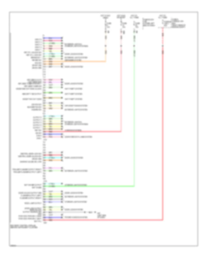
BODY CONTROL MODULES
Body Control Modules Wiring Diagram for Nissan NV1500 SV 2012
List of elements for Body Control Modules Wiring Diagram for Nissan NV1500 SV 2012:
- Acc sw
- Air con sw
- Air conditioning system
- Anti-theft system
- Bat (f/l)
- Bat (fuse)
- Bat saver output
- Bcm (body control module) (behind instrument cluster)
- Blower fan sw
- Brake sw 1
- Can-h
- Can-l
- Central door lock sw
- Central door unlock sw
- Computer data lines system
- Defogger system
- Door lock output door unlock output (as,rr,rl,bd)
- Door locks system
- Door sw (slide, bk lwr)
- Door unlock output (dr)
- Dr sw (as)
- Dr sw (dr)
- Dr sw (rr)
- Exterior lights & interior lights systems
- Exterior lights system
- Flasher output (left)
- Flasher output (right)
- Fuse & fusible link box (right rear of engine compt)
- Fuse 10a
- Fuse block (j/b) (lower left end of dash)
- Fusible link j 40a
- Gnd
- Hazard sw
- Hot at all times
- Hot in acc or on
- Hot in on or start
- Ign sw
- Immob one way comm (clock)
- Immob two way comm
- Input 1
- Input 2
- Input 3
- Input 4
- Input 5
- Interior lights system
- Key cyl lock sw
- Key cyl unlock sw
- Key sw
- Keyless & auto light sens gnd
- Keyless tuner pwr sply
- Keyless tuner sig
- M18
- M19
- M20
- M39
- M57 (left end of dash)
- Nca
- Output 1
- Output 2
- Output 3
- Output 4
- Output 5
- Pnk
- Power windows system
- Pwr wdw pwr sply (bat)
- Pwr wdw pwr sply (rap)
- Red
- Room lamp output
- Rr def sw
- Security ind output
- Trailer flasher output (left)
- Trailer flasher output (right)
- Warning systems
 Русский