BODY CONTROL MODULES
Body Control Modules Wiring Diagram for Pontiac Vibe 2009
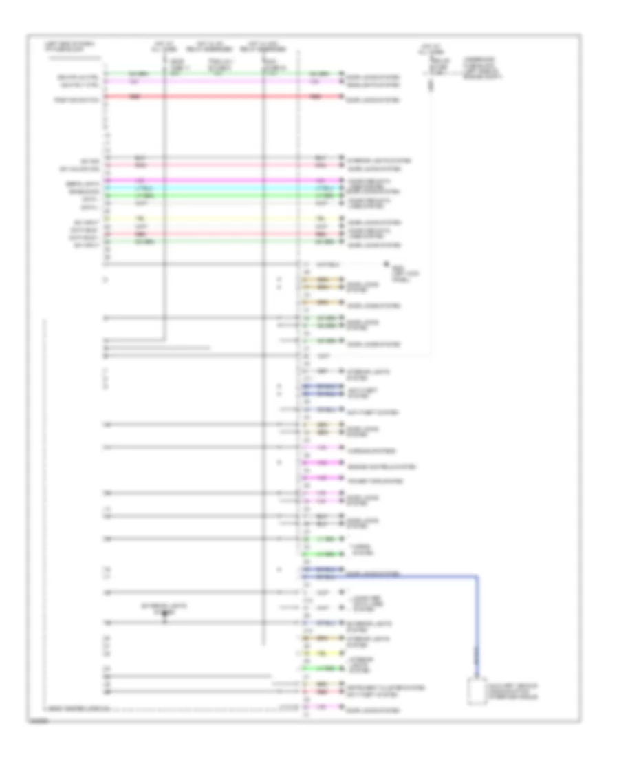
List of elements for Body Control Modules Wiring Diagram for Pontiac Vibe 2009:
- (left end of dash) i/p fuse block
- Acc fuse 24 7.5a
- Anti-theft system
- Auxiliary vehicle communication interface module
- Body control module
- Computer data lines system
- Computer data lines system door locks system
- Data +
- Data -
- Data bus +
- Data bus -
- Door fuse 11 25a
- Door locks system
- Dr mtr un ctrl
- Ecu-b fuse 10a
- Ecu-ig 1 fuse 6 10a
- Enable sig
- Engine controls system
- Exterior lights system
- G200 (left kick panel)
- Hdlp rly ctrl
- Headlights system
- Horns system
- Hot at all times
- Hot w/ acc relay energized
- Hot w/ ig1 relay energized
- Instrument cluster system
- Interior lights system
- Pnk
- Position switch
- Power tops system
- Red
- Serial data
- Sw input
- Sw sig
- Sw unlock sig
- Underhood fuse block (left side of engine compt)
- Warning systems
- X11
- X13
 English