BODY CONTROL MODULES
Body Control Modules Wiring Diagram (1 of 2) for Toyota Sequoia SR5 2004

List of elements for Body Control Modules Wiring Diagram (1 of 2) for Toyota Sequoia SR5 2004:
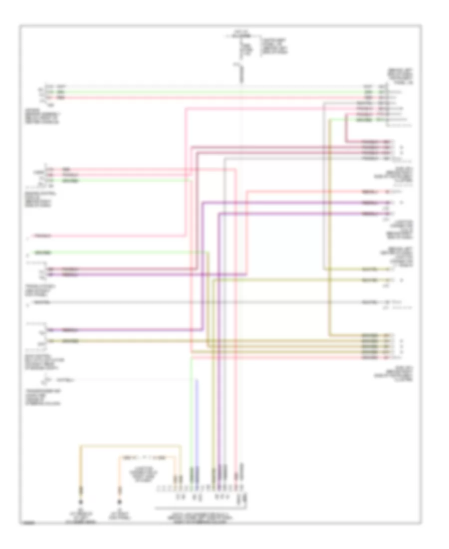
Body Control Modules Wiring Diagram (2 of 2) for Toyota Sequoia SR5 2004
List of elements for Body Control Modules Wiring Diagram (2 of 2) for Toyota Sequoia SR5 2004: