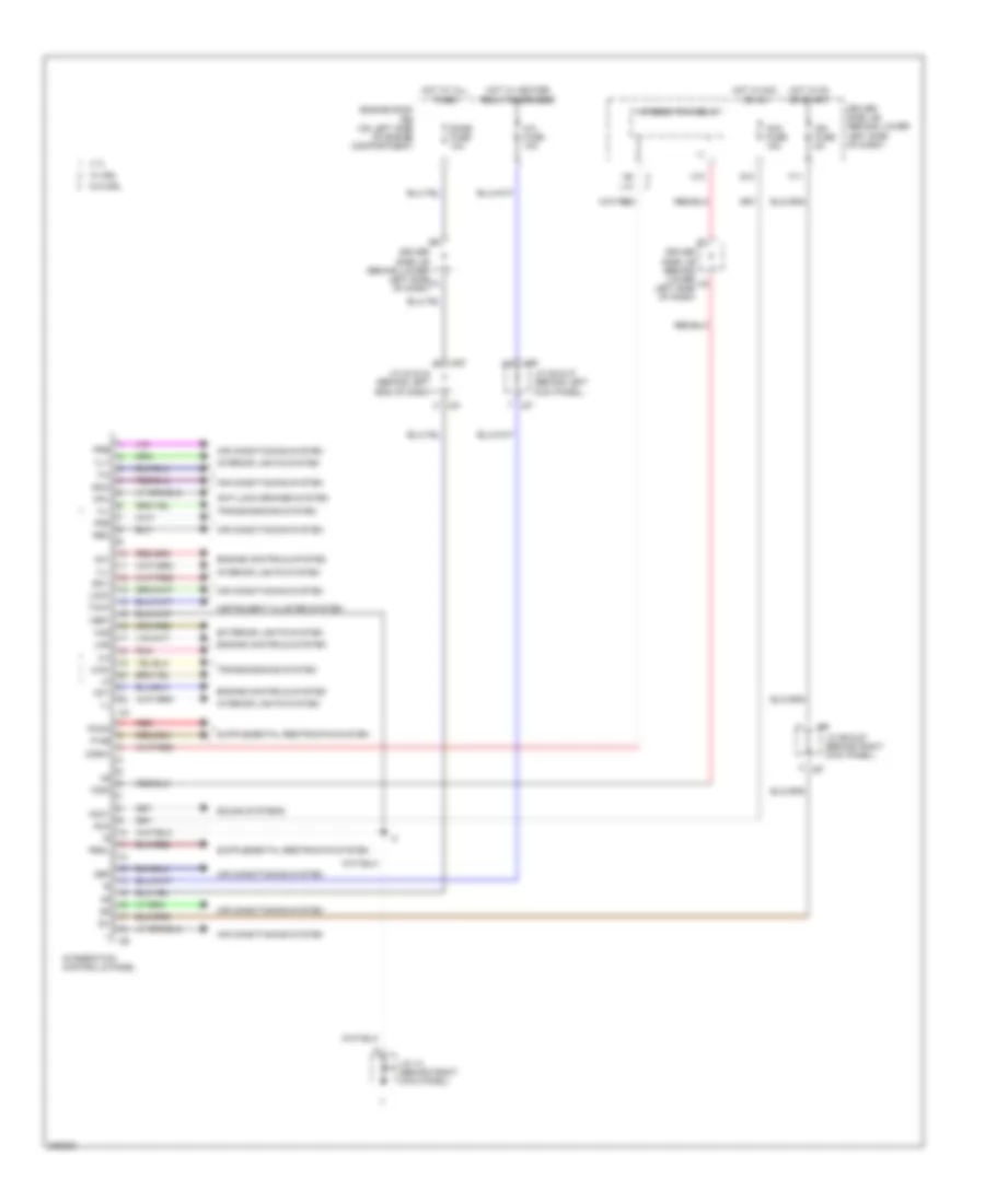
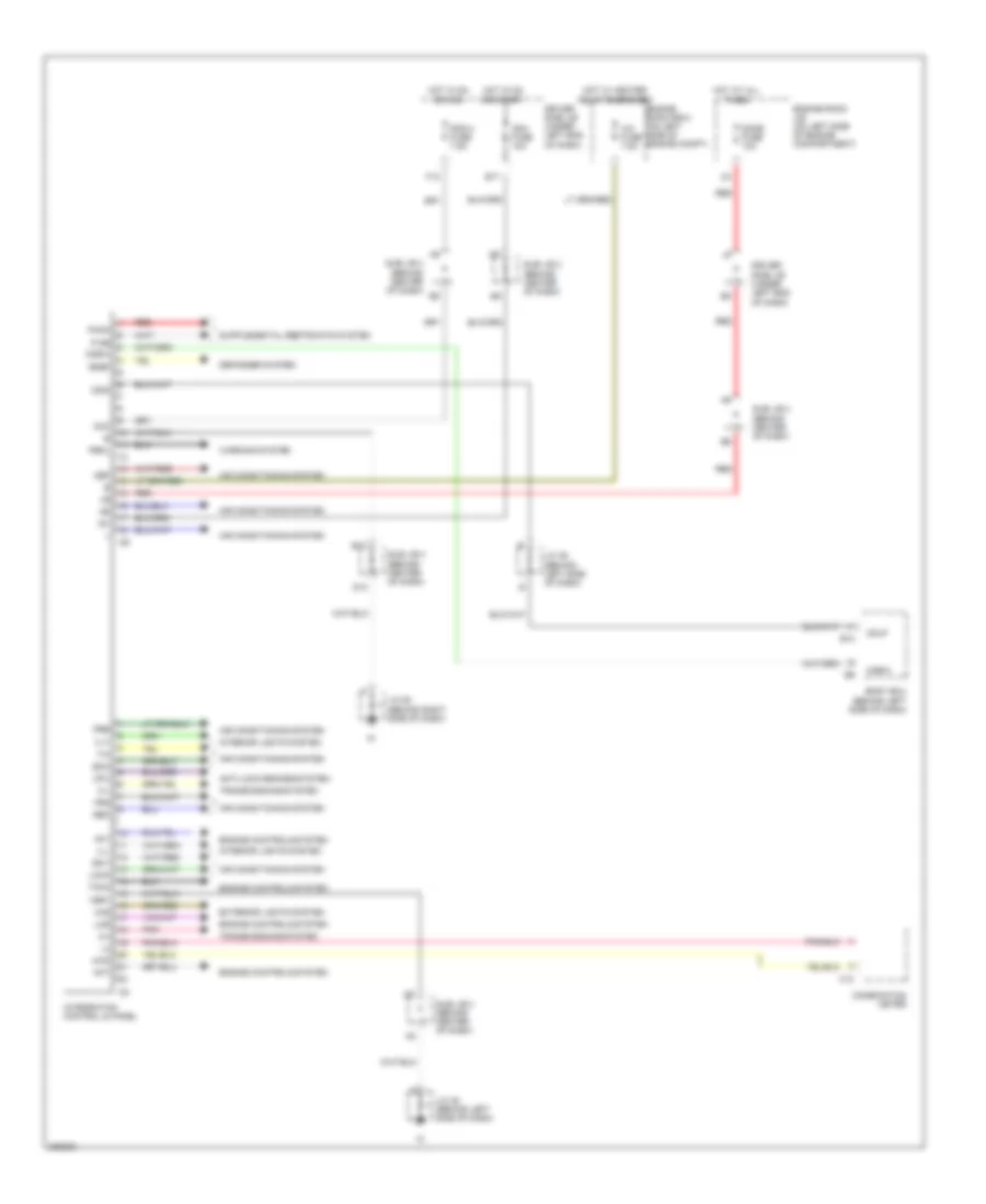
BODY CONTROL MODULES
Body ECU Wiring Diagram, Double Cab for Toyota Tundra Limited 2006

List of elements for Body ECU Wiring Diagram, Double Cab for Toyota Tundra Limited 2006:
- (behind left side of dash) j/c 45
- A10
- A19
- Acc
- Act+
- Act-
- Actd
- Acty
- Altl
- Anti-theft system
- B10
- B11
- Bdr
- Becu
- Body ecu (behind left side of dash)
- Bzr
- Cargo lp fuse 7.5a
- Cgb
- Cgid
- Cglp
- Cgsw
- Computer data lines system
- D10
- Dcty
- Dim
- Door 2 fuse 30a
- Door locks system
- Dop
- Driver side j/b (under left end of dash)
- Ecu-b fuse 7.5a
- Ecu-ig fuse 10a
- Engine room j/b (on left side of engine compartment)
- Exterior lights system
- Ffog
- Fusible link block (on left side of engine compt)
- G11
- Gnd
- H-on
- Hcty
- Head
- Headlights system
- Hind
- Horn
- Horns system
- Hot at all times
- Hot in acc or on
- Hot in on or start
- Hrly
- I25
- Ile
- Ind
- Integration control & panel
- Interior lights system
- J/c 46 (behind left side of dash)
- Ksw
- Ksw2
- Lswl
- Lswr
- Mpx1
- Mpx2
- Mpx3
- Obd2
- Pcty
- Pkb
- Pnk
- Power windows system
- Prg
- Rad 2 fuse 7.5a
- Rda
- Rlcy
- Rld
- Rlu
- Rrcy
- Rrd
- Rru
- Starting/charging system
- Sub j/b 3 (behind center of dash)
- Sub j/b 4 (behind center of dash)
- Tail
- Trly
- Warning system
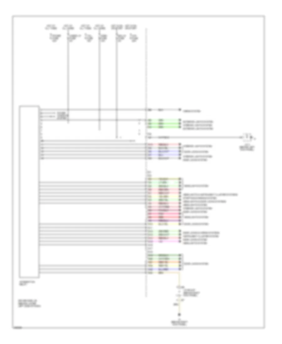
Integration Control and Panel Wiring Diagram, Access/Standard Cab for Toyota Tundra Limited 2006
List of elements for Integration Control and Panel Wiring Diagram, Access/Standard Cab for Toyota Tundra Limited 2006:
- 2-4
- 4.7l
- 4wd
- A/c fuse 10a
- Ac1
- Acc
- Acc fuse 15a
- Acc1
- Act
- Air conditioning system
- Anti-lock brakes system
- Cgid
- Cgsw
- Cpu
- Def
- Dome fuse 10a
- Driver side j/b (behind lower left side of dash)
- Engine controls system
- Engine room r/b (on left side of engine compartment)
- Exterior lights system
- F11
- Frs
- G10
- H-l
- H10
- Haz
- Hot at all times
- Hot in acc or on
- Hot in on or start
- Hot w/ heater relay energized
- I24
- I25
- Ig+
- Ign fuse 5a
- Il-
- Ill+
- Ill-
- Instrument cluster system
- Integration control & panel
- Integration relay
- Interior lights system
- J/c 13 (behind right kick panel)
- J/c 23 & 24 (behind left end of dash)
- J/c 26 & 27 (behind left kick panel)
- J/c 66 & 67 (behind right kick panel)
- J23
- J24
- J26
- J27
- J66
- J67
- L10
- Lms
- Lock
- P-ab
- Paon
- Pbkl
- Pnk
- Pre
- Rec
- Red
- Sg-1
- Sg-2
- Sound systems
- Tach
- Transmissions system
- Ver1
- W/ drl
- W/o drl
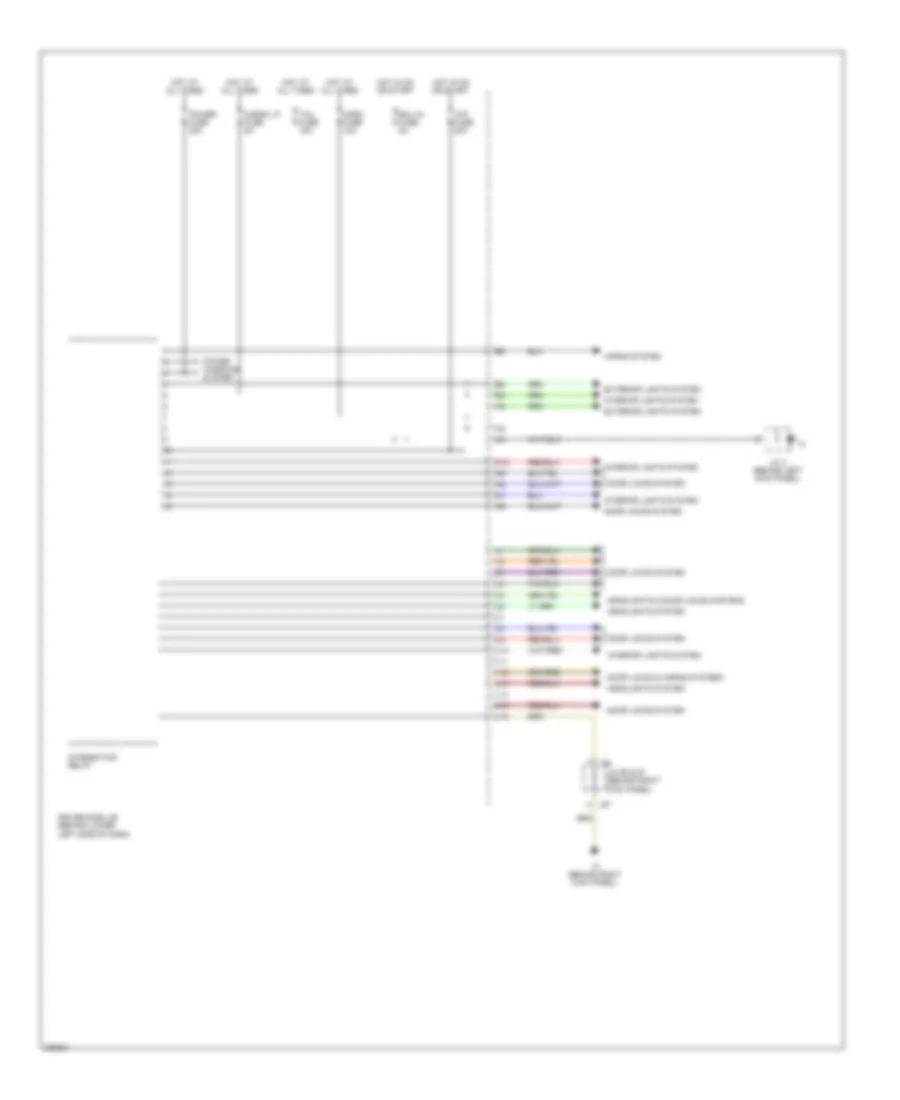
Integration Control and Panel Wiring Diagram, Double Cab for Toyota Tundra Limited 2006
List of elements for Integration Control and Panel Wiring Diagram, Double Cab for Toyota Tundra Limited 2006:
- 2-4
- 4wd
- A/c fuse 7.5a
- Ac1
- Acc
- Act
- Air conditioning system
- Anti-lock brakes system
- B10
- Body ecu (behind left side of dash)
- C12
- Cgid
- Cglp
- Cgsw
- Combination meter
- Cpu
- D10
- Def
- Defogger system
- Dome fuse 10a
- Driver side j/b (under left end of dash)
- E17
- Engine controls system
- Engine room j/b (on left side of engine compartment)
- Engine room r/b 2 (on left side of engine compt)
- Exterior lights system
- F12
- Frs
- H-l
- Haz
- Hot at all times
- Hot in on or acc
- Hot in on or start
- Hot w/ heater relay energized
- I24
- I25
- Ig+
- Ign1 fuse 10a
- Ill+
- Ill-
- Integration control & panel
- Interior lights system
- J/c 45 (behind left side of dash)
- J/c 46 (behind left side of dash)
- J/c 58 (behind right side of dash)
- Lms
- Lock
- P-ab
- Paon
- Pbkl
- Pnk
- Pre
- Rad 2 fuse 7.5a
- Rdef
- Rec
- Red
- Sg-1
- Sg-2
- Sub j/b 3 (behind center of dash)
- Sub j/b 4 (behind center of dash)
- Taco
- Transmissions system
- Ver1
- Warning system
Integration Relay Wiring Diagram, Access/Standard Cab with DRL for Toyota Tundra Limited 2006
List of elements for Integration Relay Wiring Diagram, Access/Standard Cab with DRL for Toyota Tundra Limited 2006:
- Cargo lp fuse 5a
- Door locks & horns systems
- Door locks system
- Driver side j/b (behind lower left side of dash)
- Ecu ig fuse 5a
- Exterior lights system
- F j66
- H j67
- H10
- Headlights & door locks systems
- Headlights & instrument cluster systems
- Headlights system
- Horn fuse 10a
- Horns system
- Hot at all times
- Hot in on or start
- Ih (behind right kick panel)
- Instrument cluster system
- Integration relay
- Interior lights system
- J/c 3 (behind left kick panel)
- J/c 66 & 67 (behind right kick panel)
- N10
- N11
- N12
- N13
- N14
- N15
- N16
- N17
- N18
- N19
- N20
- N21
- N22
- N23
- N24
- Pnk
- Power fuse 30a
- Power windows system
- Red
- Starting/charging system
- Tail fuse 15a
- Wip fuse 20a
Integration Relay Wiring Diagram, Access/Standard Cab without DRL for Toyota Tundra Limited 2006
List of elements for Integration Relay Wiring Diagram, Access/Standard Cab without DRL for Toyota Tundra Limited 2006:
- Cargo lp fuse 5a
- Door locks & horns systems
- Door locks system
- Driver side j/b (behind lower left side of dash)
- Ecu ig fuse 5a
- Exterior lights system
- F j66
- H j67
- H10
- Headlights & door locks systems
- Headlights system
- Horn fuse 10a
- Horns system
- Hot at all times
- Hot in on or start
- Ih (behind right kick panel)
- Integration relay
- Interior lights system
- J/c 3 (behind left kick panel)
- J/c 66 & 67 (behind right kick panel)
- L10
- L11
- L12
- L13
- L14
- L15 l15
- L16
- Power fuse 30a
- Power windows system
- Tail fuse 15a
- Wip fuse 20a