BODY CONTROL MODULES
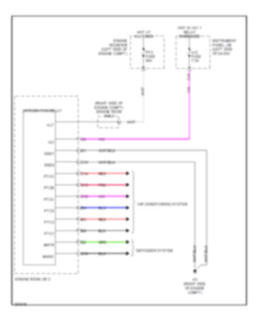
Body ECU Wiring Diagram (1 of 2) for Toyota Yaris L 2013

List of elements for Body ECU Wiring Diagram (1 of 2) for Toyota Yaris L 2013:
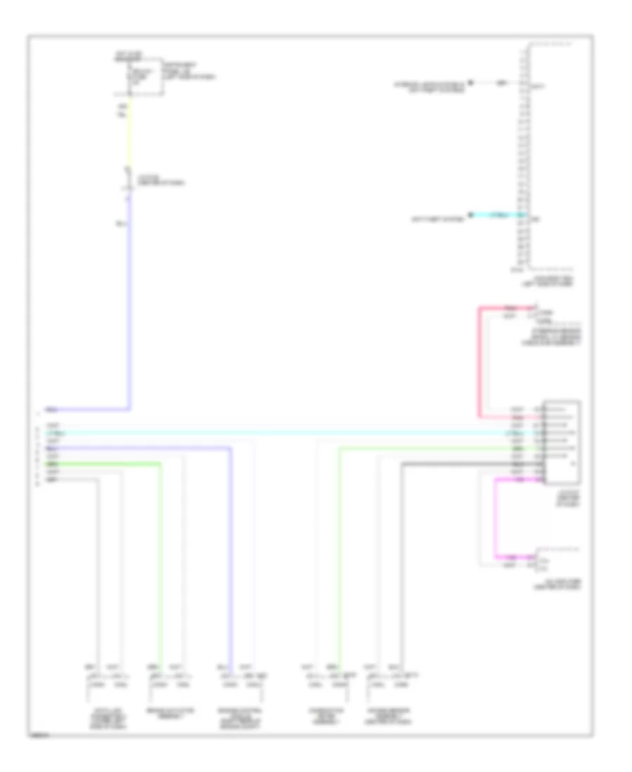
Body ECU Wiring Diagram (2 of 2) for Toyota Yaris L 2013
List of elements for Body ECU Wiring Diagram (2 of 2) for Toyota Yaris L 2013:
Integration Control and Panel Wiring Diagram for Toyota Yaris L 2013
List of elements for Integration Control and Panel Wiring Diagram for Toyota Yaris L 2013: