BODY CONTROL MODULES
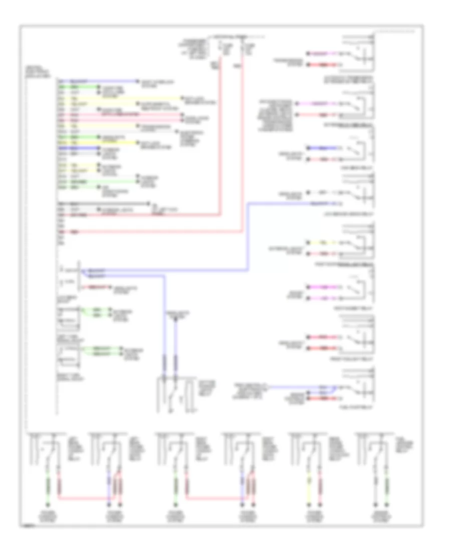
Central Electronic Module Wiring Diagram (1 of 2) for Volvo XC90 2004

List of elements for Central Electronic Module Wiring Diagram (1 of 2) for Volvo XC90 2004:
- 15a
- A10
- A11
- A12
- A13
- A14
- A15
- A16
- A17
- A18
- A19
- A20
- Acc
- Anti-theft system
- B10
- B11
- B12
- B13
- B14
- B15
- B16
- B17
- B18
- B19
- B20
- Body computer system (rear electronic module pin a4)
- C10
- C11
- C12
- C13
- C14
- C15
- C16
- C17
- C18
- C19
- C20
- Central electronic module (cem)
- Computer data lines system
- Door locks system
- Engine controls system
- Exterior lights system
- Headlights system
- Horns system
- Hot at all times
- Ignition switch
- Key in
- Lock
- Off
- Pnk
- Seats system
- Start
- Starting/ charging system
- To fuel pump relay (diagram 2 of 2)
- Trunk, tailgate, fuel doors system
- Wiper/ washer system
- Wiper/washer system
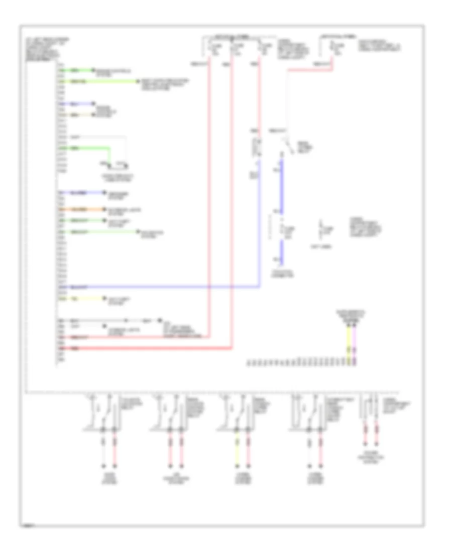
Central Electronic Module Wiring Diagram (2 of 2) for Volvo XC90 2004
List of elements for Central Electronic Module Wiring Diagram (2 of 2) for Volvo XC90 2004:
- Air conditioning system
- Air conditioning, instrument cluster, seats, exterior lights, engine controls, transmissions, horns & wiper/ washer systems
- Anti-lock brakes system
- Automatic transmission extended d2 feed relay
- Central electronic module (cem)
- Computer data lines system
- D10
- D11
- D12
- D13
- D14
- D15
- D16
- D17
- D18
- D19
- D20
- Daytime running lights relay
- Door locks system
- Electronic power steering system
- Engine controls system
- Extended d1 feed relay
- Exterior lights system
- From central electronic a module (cem) (diagram 1 of 2)
- Front foglight relay
- Fuel leakage control relay
- Fuel pump relay
- Fuse c23 20a
- Fuse c27 10a
- G6 (at left kick panel)
- Headlights system
- High beam relay
- Hot at all times
- Infotainment relay
- Interior lights system
- Left rear power window down relay
- Left rear power window up relay
- Left turn signal shunt
- Low beam shunt
- Low beam/bi-xenon relay
- Passenger compartment fuse box (at left end of dash)
- Pnk
- Position/parking light relay
- Power windows system
- Rear doors power window childlock relay
- Red
- Right rear power window down relay
- Right rear power window up relay
- Right turn signal shunt
- Shift interlock system
- Sound system
- Transmissions system
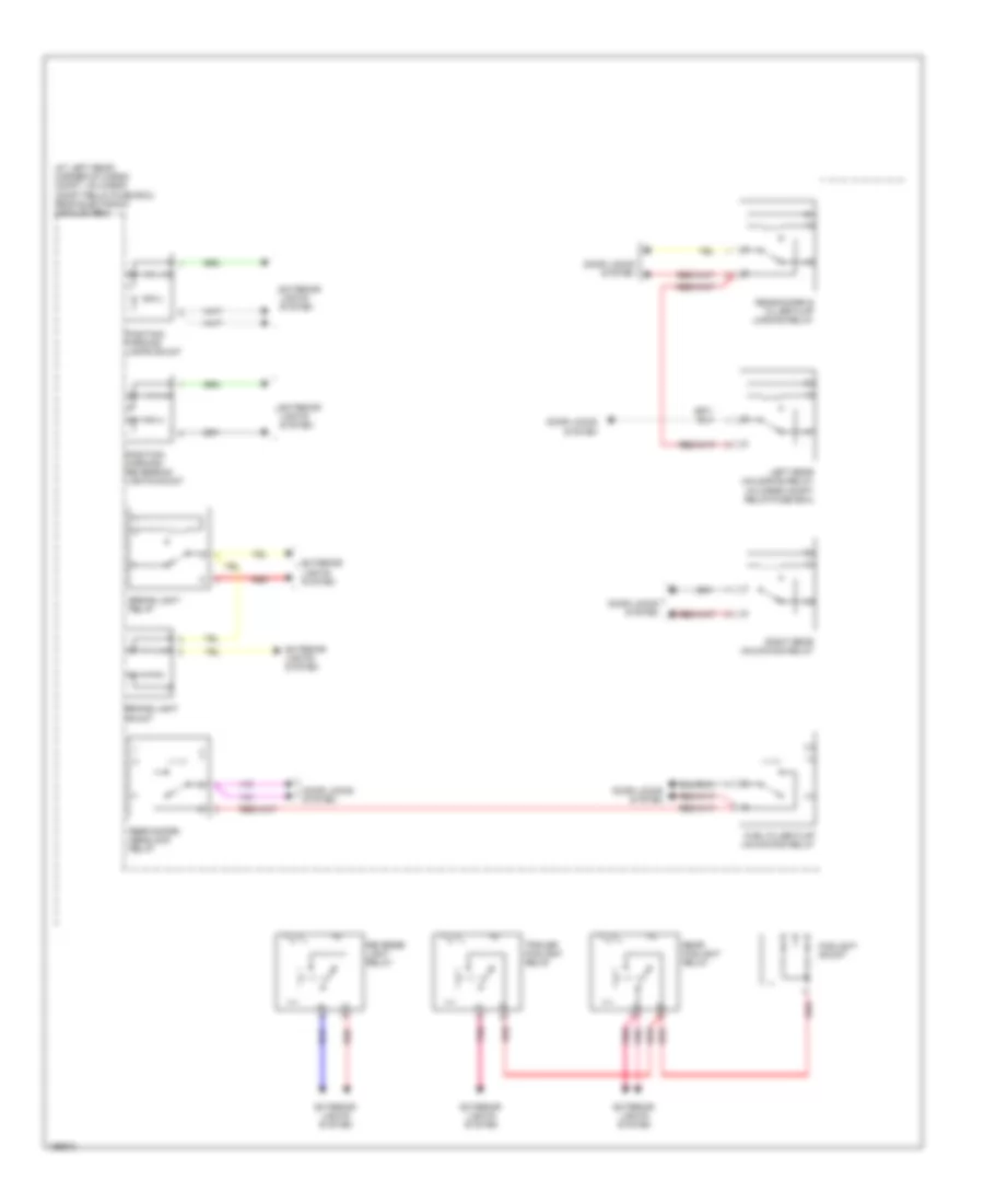
Rear Electronic Module Wiring Diagram (1 of 2) for Volvo XC90 2004
List of elements for Rear Electronic Module Wiring Diagram (1 of 2) for Volvo XC90 2004:
- (at left rear corner of cargo compt, on cargo compt relay/fuse box) rear electronic module (rem)
- (not used)
- A10
- A11
- A12
- A13
- A14
- A15
- A16
- A17
- A18
- A19
- A20
- Air conditioning system
- Anti-theft system
- B10
- B11
- B12
- B13
- B14
- B15
- B16
- B17
- B18
- B19
- B20
- Body computer system (central electronic module pin b6)
- Cargo compartment 12v outlet shunt
- Cargo compartment relay/fuse box (at left side of cargo compt)
- Computer data lines system
- D10
- D11
- D12
- D13
- D14
- D15
- D16
- D17
- D18
- D19
- D20
- Defogger system
- Distribution
- Door locks system
- Engine controls system
- Exterior lights system
- Fuse d1 10a
- Fuse d15 20a
- Fuse d16
- Fuse d2 10a
- Fuse d5 5a
- Fuse e1 40a
- G72 (at left rear of passenger's compt, near floor)
- Hot at all times
- Interior lights system
- Intermittent rear window wiper on/off relay
- Main fuse box (next to battery, in cargo compartment)
- Navigation system
- Power
- Rear 15 feed relay
- Rear climate control system relay
- Rear window wiper relay
- Red
- System
- Tailgate unlocking relay
- Tow hitch connector
- Wiper/ washer system
Rear Electronic Module Wiring Diagram (2 of 2) for Volvo XC90 2004
List of elements for Rear Electronic Module Wiring Diagram (2 of 2) for Volvo XC90 2004:
- (at left rear corner of cargo compt, on cargo compt relay/fuse box) rear electronic module (rem)
- Brake light relay
- Brake light shunt
- Door locks system
- Exterior lights system
- Foglight shunt
- Fuel filler flap unlocking relay
- Left rear unlocking relay (in cargo compt relay/fuse box)
- Pnk
- Position/ parking lamps shunt
- Position/ parking/ reversing lights shunt
- Rear doors & filler flap locking relay
- Rear doors deadlock relay
- Rear foglight relay
- Red
- Reverse light relay
- Right rear unlocking relay
- Trailer foglight relay