
Buick Regal Custom 1990 - 1990 ENGINE PERFORMANCE 3.1L VIN T Self-Diagnostics
Buick Regal Custom 1990 - INTRODUCTION
Most engine control problems are the result of mechanical breakdowns, poor electrical connections or damaged vacuum hoses. Before considering the computer system as a cause of problems, perform checks and inspections covered in BASIC TESTING article. Failure to do so may result in lost diagnostic time.
If no faults were found while performing the basic tests in the BASIC TESTING article, proceed with DIAGNOSTIC PROCEDURE in this article. If no fault codes or only a non-running Code 12 is present and driveability problems exist, proceed to article TESTS W/O CODES for diagnosis by symptom (i.e. ROUGH IDLE, NO START, etc.). If only intermittent codes are present, see INTERMITTENTS in the TESTS W/O CODES article in this section.
Buick Regal Custom 1990 - SELF-DIAGNOSTIC SYSTEM DESCRIPTION
The ECM is equipped with a self-diagnostic system, which detects system failures or abnormalities. When a malfunction occurs, ECM will illuminate the SERVICE ENGINE SOON light located on instrument panel. When malfunction is detected and light is turned on, a corresponding trouble code will be stored in ECM memory. To retrieve stored codes, see RETRIEVING CODES (NON-SCAN) in this article. Malfunctions are recorded as HARD FAILURES or as INTERMITTENT FAILURES.
Buick Regal Custom 1990 - Hard Failures
Hard failures cause SERVICE ENGINE SOON light to illuminate and remain on until the malfunction is repaired. If light comes on and remains on (light may flash) during vehicle operation, cause of malfunction must be determined using diagnostic (code) charts. If a sensor fails, control unit will use a substitute value in its calculations to continue engine operation. In this condition, vehicle is functional, but loss of good driveability will most likely be encountered.
Buick Regal Custom 1990 - Intermittent Failures
Intermittent failures cause SERVICE ENGINE SOON light to flicker or illuminate and go out about 10 seconds after the intermittent fault goes away. The corresponding trouble code, however, will be retained in ECM memory. If related fault does not reoccur within 50 engine restarts, related trouble code will be erased from ECM memory. Intermittent failures may be caused by sensor, connector or wiring related problems. See INTERMITTENTS in TESTS W/O CODES article in this section.
Buick Regal Custom 1990 - DIAGNOSTIC PROCEDURE
Diagnosis of the computerized engine control system should be performed in the following order:
- Make sure all engine systems not related to the computer system are operating properly. Do not proceed with testing unless all other problems have been repaired. Appropriate DIAGNOSTIC CIRCUIT CHECK for that system MUST be performed prior to utilizing trouble code charts. See BASIC TESTING article.
- If trouble codes were displayed (other than Code 12), decide whether codes are hard or intermittent trouble codes. Hard codes will cause the SERVICE ENGINE SOON light to illuminate continuously while engine is running. See HARD OR INTERMITTENT TROUBLE CODE DETERMINATION in this article. For diagnosing hard codes, proceed to appropriate trouble code chart in this article. For diagnosing intermittent codes, go to INTERMITTENTS in TESTS W/O CODES article. Exceptions are Code 13, 15, 24, 44 and 45 charts, which may be used to help diagnose intermittent codes.
- If no trouble codes were displayed and a driveability problem exists, refer to SYMPTOMS in TESTS W/O CODES article. The comments there will send you to the proper system or component to check in SYSTEM/COMPONENT TESTS article.
- After any repairs are made, clear any trouble codes and perform the SYSTEM PERFORMANCE CHECK or the FIELD SERVICE MODE check in the BASIC TESTING G article.
Buick Regal Custom 1990 - RETRIEVING CODES (NON-SCAN)
- Turn ignition on. Do not start engine. SERVICE ENGINE SOON light should glow. Locate Assembly Line Data Link (ALDL) connector attached to ECM wiring harness. Most ALDL connectors are located under dash on driver's side of vehicle. For exact location of ALDL, see appropriate COMPONENT LOCATIONS illustration in the SYSTEM/COMPONENT TESTS article. Turn ignition on. Insert jumper wire from terminal "B" (diagnostic test terminal) to terminal "A" (ground) of ALDL connector. See Fig. 1 .
NOTE: Inserting jumper wire into test and ground terminals of ALDL connector with engine running will cause fuel injected vehicles to enter field service mode. Codes won't flash if this is done. See FIELD SERVICE MODE in BASIC TESTING article in this section. 
Fig. 1: Buick Regal Custom 1990 - Component Locations - ALDL Connector Terminal Identification - SERVICE ENGINE SOON light should begin to flash codes. Each code will be repeated 3 times. If codes are not flashed, perform DIAGNOSTIC CIRCUIT CHECK in BASIC TESTING article. To exit diagnostic mode, turn ignition off and remove jumper wire from ALDL connector.
Buick Regal Custom 1990 - READING TROUBLE CODES
The ECM stores component failure information under a related trouble code which can be recalled for diagnosis and repair. Trouble codes may be read by counting flashes of the SERVICE ENGINE SOON light, or by reading the output of a diagnostic "Scan" tester connected to the ALDL connector. The tester is faster to use, more accurate, and capable of reading information which otherwise would necessitate testing individual ECM and sensor/solenoid connector terminals with a digital voltmeter. See SCAN DATA TABLES and SCAN TESTER USAGE in this article.
NOTE: When using a "Scan" tester, there is a time delay between serial data updates. For instantaneous response, a digital voltmeter must be used.
If "Scan" tester is not available, it is possible to read flashes of the SERVICE ENGINE SOON light by grounding the diagnostic terminal of the ALDL with ignition on and engine off. For example, FLASH, FLASH, pause, FLASH, longer pause, identifies Code 21. The first series of flashes are the first digit of trouble code. The second series of flashes are the second digit of trouble code. Trouble codes are displayed starting with the lowest numbered code. Each code is displayed 3 times. Codes will continue to repeat as long as ALDL test terminal is grounded.
NOTE: Trouble codes will be recorded at various operating times. Some codes require operation of that sensor or switch for 5 seconds; others may require operation for 5 minutes or longer at normal operating temperature, road speed and load. Therefore, some codes may not set in a service bay operational mode.
NOTE: Trouble code charts should only be used if SERVICE ENGINE SOON light is illuminated (indicating a current problem exists). Exceptions are Code 13, 15, 24, 44 and 45 charts, which may be used to help diagnose intermittent codes. Anytime Codes 51, 52, 54 or 55 are displayed with another code, start with 50-series code first, then proceed to low profile numbered codes.
Buick Regal Custom 1990 ECM TROUBLE CODE DEFINITION
Code No. Circuit Affected 12 (1) No RPM reference pulse 13 Open oxygen sensor circuit 14 CTS signal voltage low 15 CTS signal voltage high 16 System voltage high 21 TPS signal voltage high 22 TPS signal voltage low 23 MAT sensor signal voltage high " M/C solenoid voltage low 24 VSS circuit 25 MAT sensor signal voltage low 26 Quad-Driver error 27, 28 & 29 Gear switch problem 31 Wastegate error (turbo) " Purge solenoid voltage high (carburetor.) " Park/Neutral switch 32 EGR system error 33 MAP sensor signal voltage high " MAF sensor signal voltage high (PFI) 34 MAP sensor signal voltage low " MAF sensor signal voltage low (PFI) " Pressure sensor circuit (carb.) 35 IAC idle speed error 38 Brake switch 39 TCC 41 No distributor reference (carburetor.) " C(3)I ignition - cam sensor loss " Cylinder select error (MEM-CAL) 42 EST circuit open or grounded 43 ESC retard signal too low 44 Lean exhaust indicated 45 Rich exhaust indicated 46 Anti-theft fault " Power steering pressure switch 48 Misfire diagnosis 51 Faulty PROM, MEM-CAL or ECM 52 Faulty/missing CALPAC or MEM-CAL 53 Faulty alternator, voltage high " EGR system malfunction " Anti-theft circuit fault 54 Fuel pump voltage low " MC solenoid voltage high (carb.) 55 Faulty ECM 61 Degraded O2 sensor 62 Gear switch error 63 EGR flow error 64 EGR flow error 65 EGR flow error " Fuel injector current low 66 A/C pressure sensor voltage out of specification
(1) Display of a Code 12 is normal when no reference pulses are received by ECM (engine not running).
Buick Regal Custom 1990 - HARD OR INTERMITTENT TROUBLE CODE DETERMINATION
During any diagnostic procedure, it must be determined if codes are hard failure codes or intermittent failure codes. Diagnostic charts will not usually help analyze intermittent codes. To determine hard codes and intermittent codes, proceed as follows:
- MANUALLY enter diagnostic mode. Read and record all stored trouble codes. Exit diagnostic mode and clear trouble codes. See CLEARING TROUBLE CODES.
- Apply parking brake and place transmission in Neutral or Park. Block drive wheels and start engine. SERVICE ENGINE SOON light should go out. Run warm engine at specified curb idle for 2 minutes and note SERVICE ENGINE SOON light.
- If SERVICE ENGINE SOON light comes on, MANUALLY enter diagnostic mode. Read and record trouble codes. This will reveal hard failure codes. Codes 13, 15, 24, 44, 45 and 55 may require a road test to reset hard failure after trouble codes were cleared.
- If SERVICE ENGINE SOON light does not come on, all stored trouble codes were intermittent failures. Exceptions are noted under each DIAGNOSTIC PROCEDURE.
Buick Regal Custom 1990 - CLEARING TROUBLE CODES
Turn ignition switch to ON position and ground diagnostic terminal lead at ALDL connector. Turn ignition switch to OFF position and remove ECM fuse from fuse block for 10 seconds. Replace fuse. Remove diagnostic terminal ground lead.
Buick Regal Custom 1990 - ECM LOCATION
On most vehicles the ECM is located behind the right side of the dash, or behind the right kick panel. On the Grand Prix and Lumina, the ECM is located on the right side of the engine compartment. On W bodies ECM is located in engine compartment, in front of right strut tower.
Buick Regal Custom 1990 - DIAGNOSTIC MATERIALS Diagnostic Aids
Diagnostic aids (located in many trouble code charts) are additional tips used to help diagnose trouble codes when inspected circuit checks out okay. Diagnostic aids may help lead to a definitive solution to that trouble code problem.
Buick Regal Custom 1990 - System Performance Check (Carbureted)
This check verifies that computerized engine control system is functioning correctly. This check should always be made after any repair of computerized engine control system. Performance check can be found by proceeding to SYSTEM PERFORMANCE CHECK in BASIC TESTING article in this section.
Buick Regal Custom 1990 - Field Service Mode Check (Fuel Injected)
On fuel injected models, SERVICE ENGINE SOON light will indicate operational mode of engine if ALDL is grounded while engine is running. This test confirms proper operation of fuel system and verifies closed loop operation. Clear codes and perform this test after any repair is completed. Field service mode check can be found by proceeding to the FIELD SERVICE MODE CHECK (FUEL INJECTED) test procedures in the BASIC TESTING article in this section.
Buick Regal Custom 1990 - Special Tools (Diagnostic)
NOTE: Special "Scan" testers plugged into the ALDL may be used to read trouble codes and check voltages in the system on the serial data line (terminal "D" on carbureted, terminal "E" on EFI and terminal "M" on EFI with P-4 systems). These testers can save a great deal of time. For additional information, see SCAN TESTER USAGE and SCAN TESTER DATA tables in this article.
The computerized engine control system is most easily diagnosed using a "Scan" tester; however, other tools may aid in diagnosing problems if a "Scan" tester is unavailable. These tools are a tachometer, dwell meter, test light, ohmmeter, digital voltmeter with 10-megohm input impedance (minimum), vacuum pump, vacuum gauge, fuel injector test lights (TBI and PFI) and 6 jumper wires 6" long (one wire with female connectors at both ends, one wire with male connector at both ends and 4 wires with male and female connectors at opposite ends). A test light, rather than a voltmeter, must be used when indicated by a diagnostic chart.
On carbureted models, a dwell meter can be used to measure the time M/C solenoid is on or off. Dwell reading indicates if M/C solenoid is working, as well as fuel mixture strength (rich or lean). The dwell meter is set on the 6-cylinder scale regardless of the number of cylinders in engine.
Dwell meter is connected to Green connector located near carburetor. This connector should not be connected to any circuit EXCEPT when testing with dwell meter. DO NOT allow terminal wire to come in contact with any ground source, including rubber hoses.
NOTE: If engine operation seems to change when dwell meter is connected to Green connector, remove dwell meter and use another type. Some models may not be compatible with computerized engine control system.
Before engine reaches operating temperature, dwell should be fixed between 10-50 degrees, indicating open loop operation. With engine at operating temperature and idling, dwell meter needle should be varying between 10-50 degrees. This indicates closed loop operation. If (after reaching normal operating temperature) dwell is fixed between 10-50 degrees, less than 10 degrees or more than 50 degrees, refer to SYSTEM PERFORMANCE CHECK in BASIC TESTING article in this section.
Buick Regal Custom 1990 - SCAN TESTER USAGE
NOTE: Prior to connection of "Scan" tester to vehicle, diagnostic system should be checked to determine if system is operating properly and if information received by "Scan" tester will be accurate. This is done by performing appropriate DIAGNOSTIC CIRCUIT CHECK in BASIC TESTING article. If vehicle does not pass diagnostic circuit check, information received by "Scan" tester may be invalid.
The "Scan" tester is a specialized tester which, when plugged into ALDL, can be used to diagnose on-board computer control systems by providing instant access to circuit voltage information without need to crawl under dash or hood to back-probe sensors and connectors. "Scan" testers cut down diagnostic time dramatically by furnishing input data (voltage signals) which can be compared to specification parameters. See SCAN DATA tables in this article. They may also furnish information on output device (solenoids and motors) status. However, status parameters are only an indication that output signals have been sent to devices by the ECM. It does not indicate if devices have responded properly to that signal. This will need to be verified at output device using a voltmeter or test light.
NOTE: Code 12 should always exist when ALDL is grounded with key on and engine not running, but may not be indicated by all makes of "Scan" testers.
If trouble codes are not present, this is not an indication that there is not a problem. Driveability related problems with codes displayed occur about 20 percent of the time, while driveability problems without codes occur about 80 percent of the time. Sensors that are out of specification WILL NOT set a trouble code but WILL cause driveability problems. Using a "Scan" tester is easiest method of checking sensor specifications and other data parameters. Tester is also useful in finding intermittent wiring problems by wiggling wiring harnesses and connections (key on, engine off) while observing data parameters. See SCAN DATA tables in this article.
NOTE: Information obtained by "Scan" tester is only as accurate as the tester itself. If erroneous voltage signals are suspected, it will be necessary to verify tester information using a digital voltmeter and wiring schematic. If non-existent codes are displayed, turn ignition off, remove tester, turn ignition on and ground ALDL test terminal. If same codes are not flashed by SERVICE ENGINE SOON light that were indicated by "Scan" tester, tester cannot be used on vehicle and information obtained by it will not be guaranteed accurate.
Buick Regal Custom 1990 - SCAN DATA
NOTE: Information contained in the following tables is typical of readings taken on vehicle with engine idling, upper radiator hose hot, closed throttle, transmission in Park or Neutral, closed loop status achieved and all accessories off (except as noted in tables). Data parameters are updated every 1 1/4 seconds. On systems using P-4 computers, parameter updates are more often. Not all devices & systems are used on all models.
Buick Regal Custom 1990 PORT FUEL INJECTION
Tester Position Units Measured Nominal Data Value A/C Clutch On/Off Off (on with A/C) A/C Request Yes/No No/Yes (with request) AIR Divert Sol. On/Off On (air to switching sol.) Off (air to atmosphere) AIR Switching Sol. On/Off On (to exhaust manifold) Off (to catalytic converter) BARO Volts 3-4.5 Battery Voltage Volts 13.5-14.5 Block Learn Counts 118-138 (128 normal) Canister Purge Sol. On/Off On/engine cold (idle some) Clear Flood On/Off See tester manual Coolant Fan On/Off Off below 216?F (102?C) Coolant Temp. ?C 85-105? (norm. temperature) Crank RPM RPM 100-900 Cross Counts Counts 0-255 EGR Solenoid On/Off On when energized EGR Duty Cycle 0-100% 0/closed-100/fully open Fan Relay On/Off On when energized Fan Request On/Off On with request Fuel Back-Up Yes/No Yes when engaged IAC Counts 0-50 Ignition/Crank On/Off On with ignition/crank Injector Pulse Width Mil./Sec .8-3.0 INT (Integrator) Counts 110-145 (128 normal) Knock Retard (ESC) Counts 0-255 Knock Signal Yes/No Yes when knock exists MAT ?C 10-90? MAP Volts 1 (idle) to 4.5 (WOT) Open/Closed Loop Status OL/CL Closed/Open during extended idle O2 Sensor Millivolts 100 (lean) to 999 (rich) P/N Switch P/N/RDL Park/Neutral P/S Switch Norm/Hi Normal PROM I.D. PROM # Original factory number RPM RPM Spec. +/-25 RPM Drive (auto.), Spec. +/-50 RPM Neut. (man.) Spark Advance No. Deg. Varies TCC On/Off Off (On with command) TPS Volts 1.25 (idle) to 5.0 (WOT) Throttle Angle 0-100% 0 (idle) to 100 (WOT) Trouble Codes Code # No codes Turbo Boost On/Off On when activated Upshift Light (M/T) On/Off Off VSS or MPH MPH 0-Actual Wastegate By-Pass On/Off On when by-passed Water Injection On/Off On when injecting 1st Gear Switch On/Off On/1st gear only 3rd Gear Switch On/Off On/3rd & 4th gear 4th Gear Switch On/Off On/4th gear
Buick Regal Custom 1990 - DIAGNOSTIC TESTS
NOTE: The following diagnostic flow charts and mini-schematics are supplied courtesy of General Motors Corp.
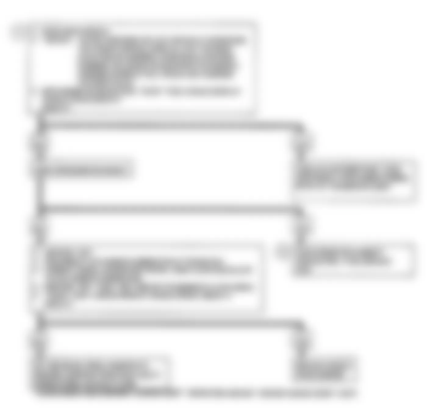
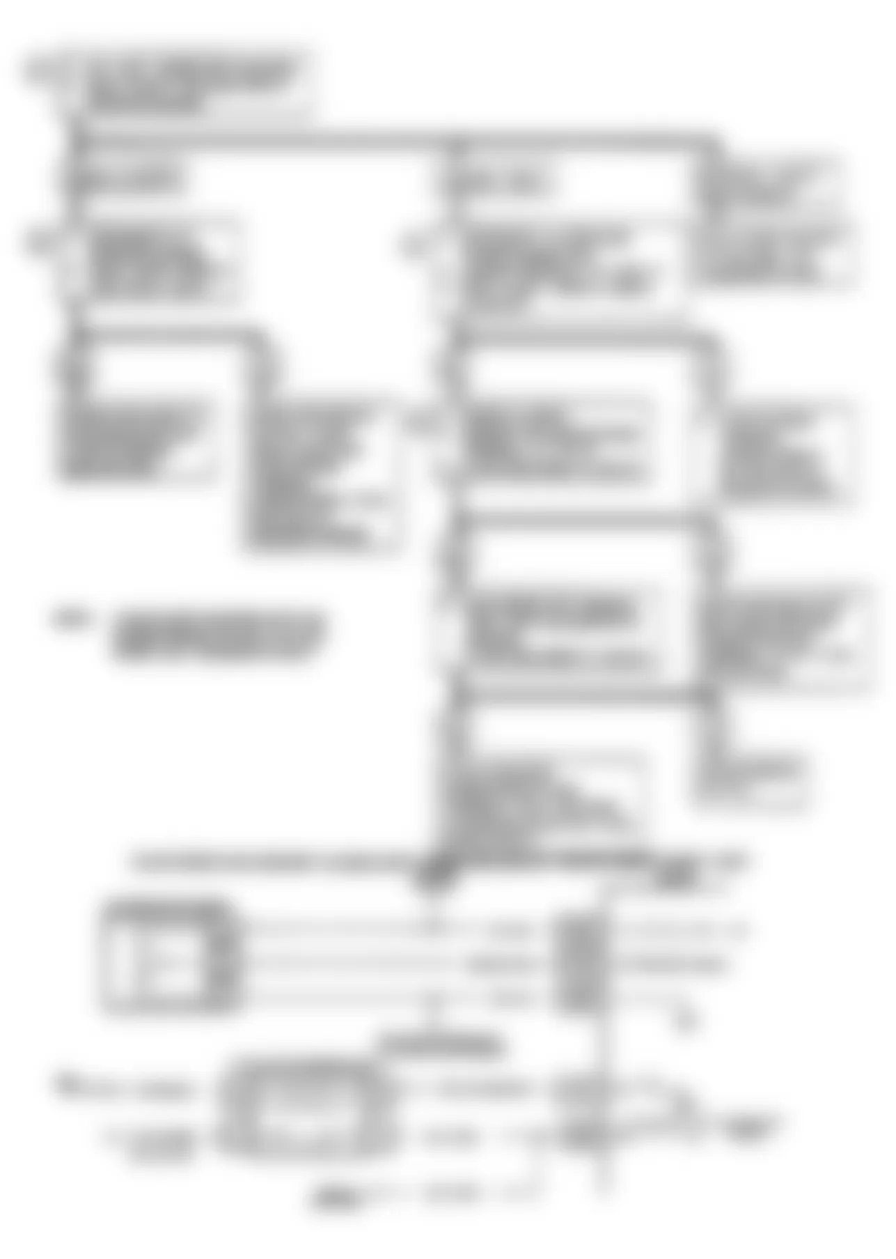
Buick Regal Custom 1990 - CODE 13: OPEN OXYGEN SENSOR CIRCUIT
NOTE: Test numbers refer to test numbers on diagnostic chart.
- Code 13 will set when the following conditions occur:
- Engine at normal operating temperature.
- At least 2 minutes elapsed since start-up.
- Oxygen signal voltage steady between .35 and .55 volt.
- Throttle angle greater than 3-6 percent (about .3 volt greater than closed throttle voltage).
- All conditions must be met for about 60 seconds.
If conditions for a Code 13 exist, the system will not go "closed loop".
- This test determines if the sensor, wiring or ECM is the cause of Code 13.
- When conducting this test, use only a high impedance (10-megohm) digital volt-ohmmeter. This tests the continuity of the sensor signal and ground circuits. If ground circuit is open, the ECM voltage on the signal circuit will be greater than .6 volt.
Buick Regal Custom 1990 - Diagnostic Aids
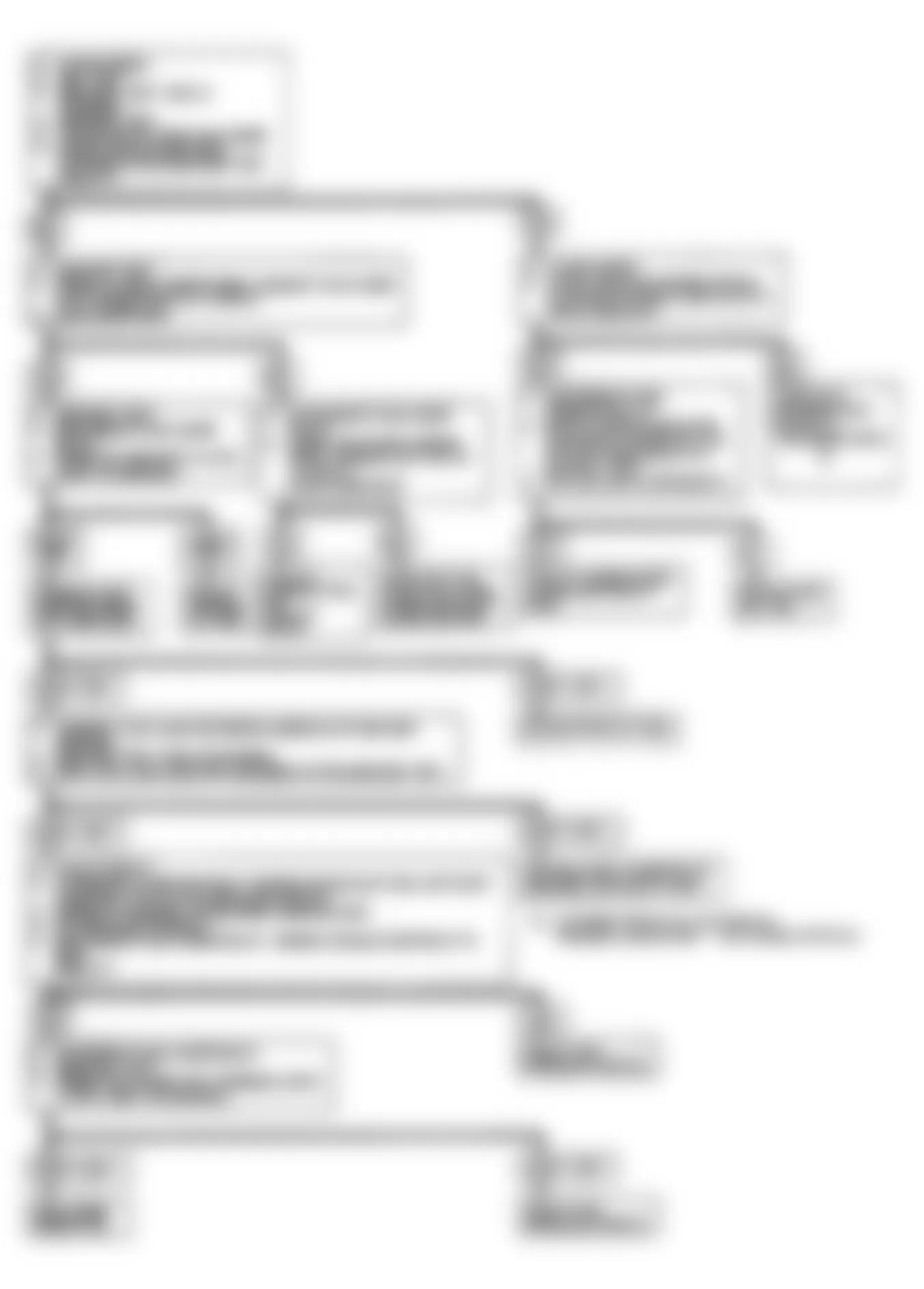
Normal "Scan" tester voltage varies between 100 and 999 mV while in "closed loop". Code 13 will set in one minute if voltage remains between .35-.55 volt; however, system will go "open loop" in about 15 seconds.


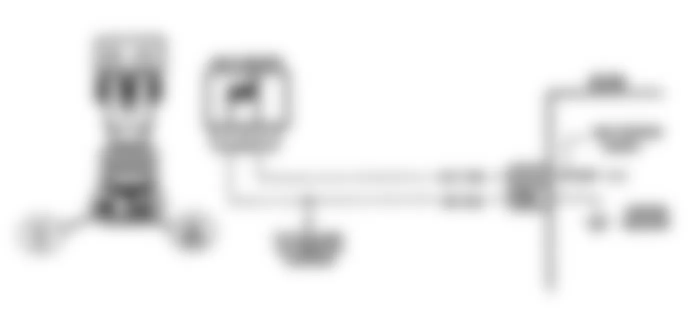
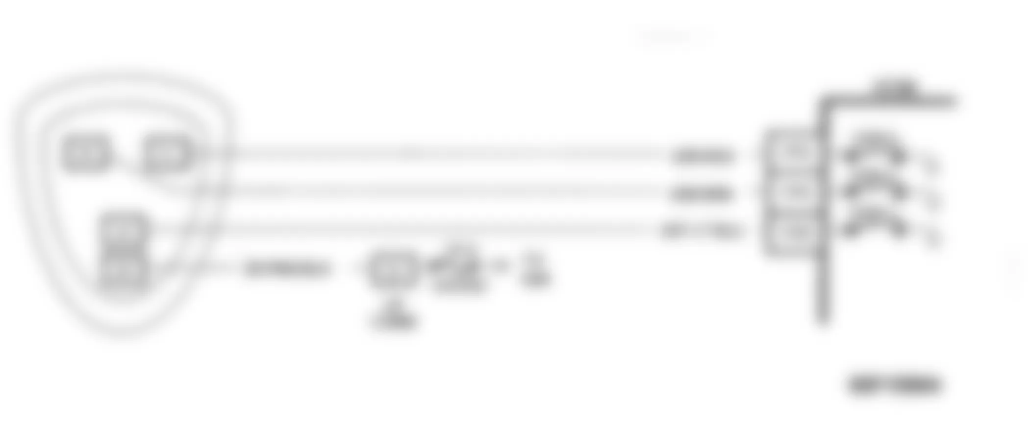
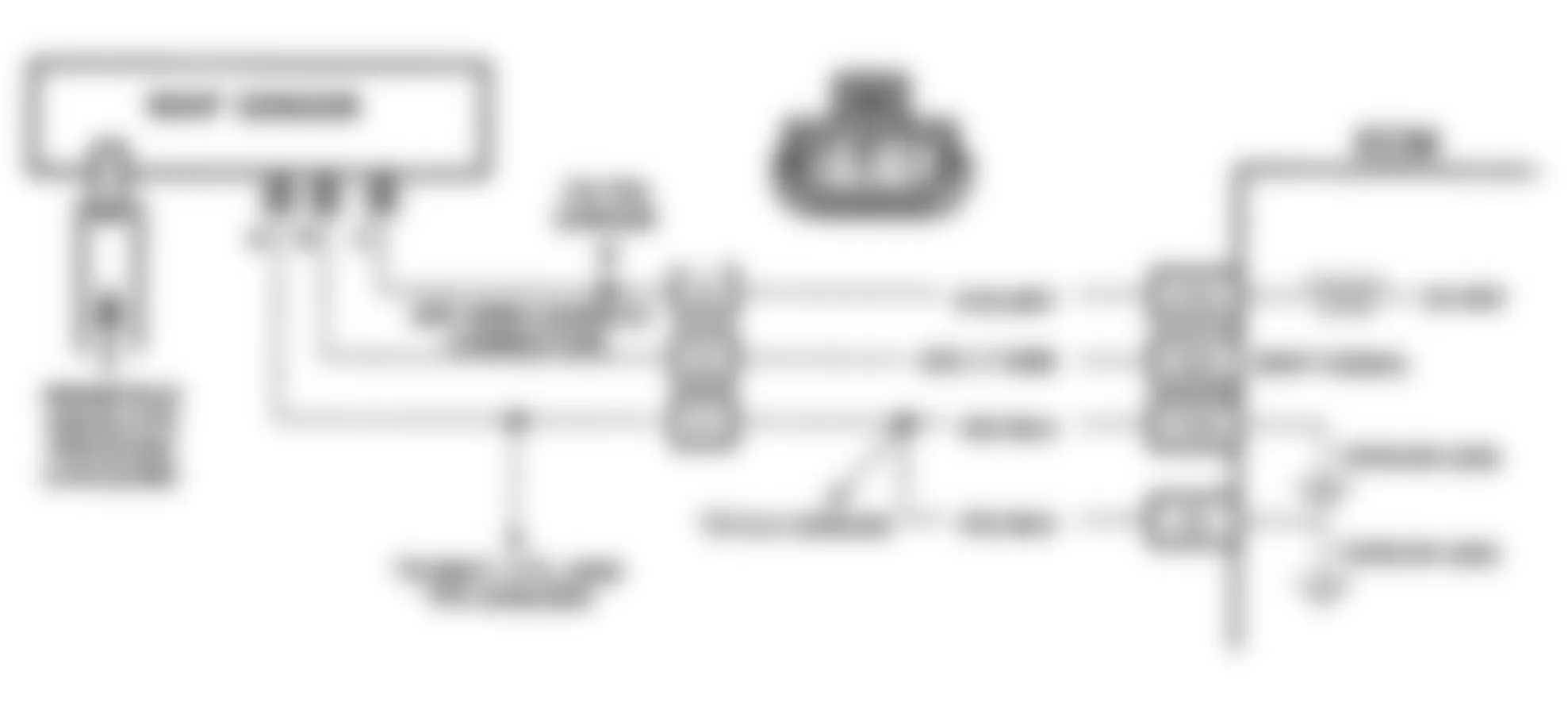
Fig. 4: Buick Regal Custom 1990 - Component Locations - Code 13: Open O2 Sensor Schematic (W Body)

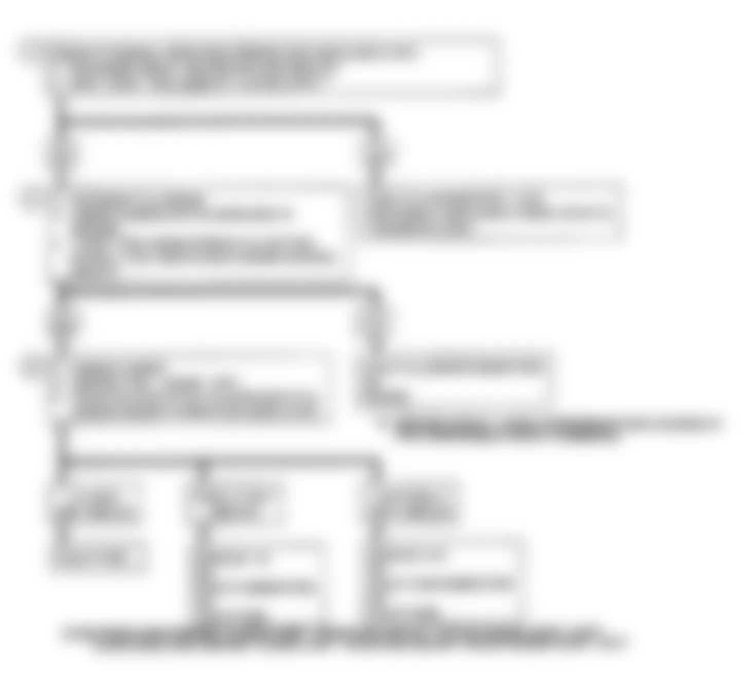
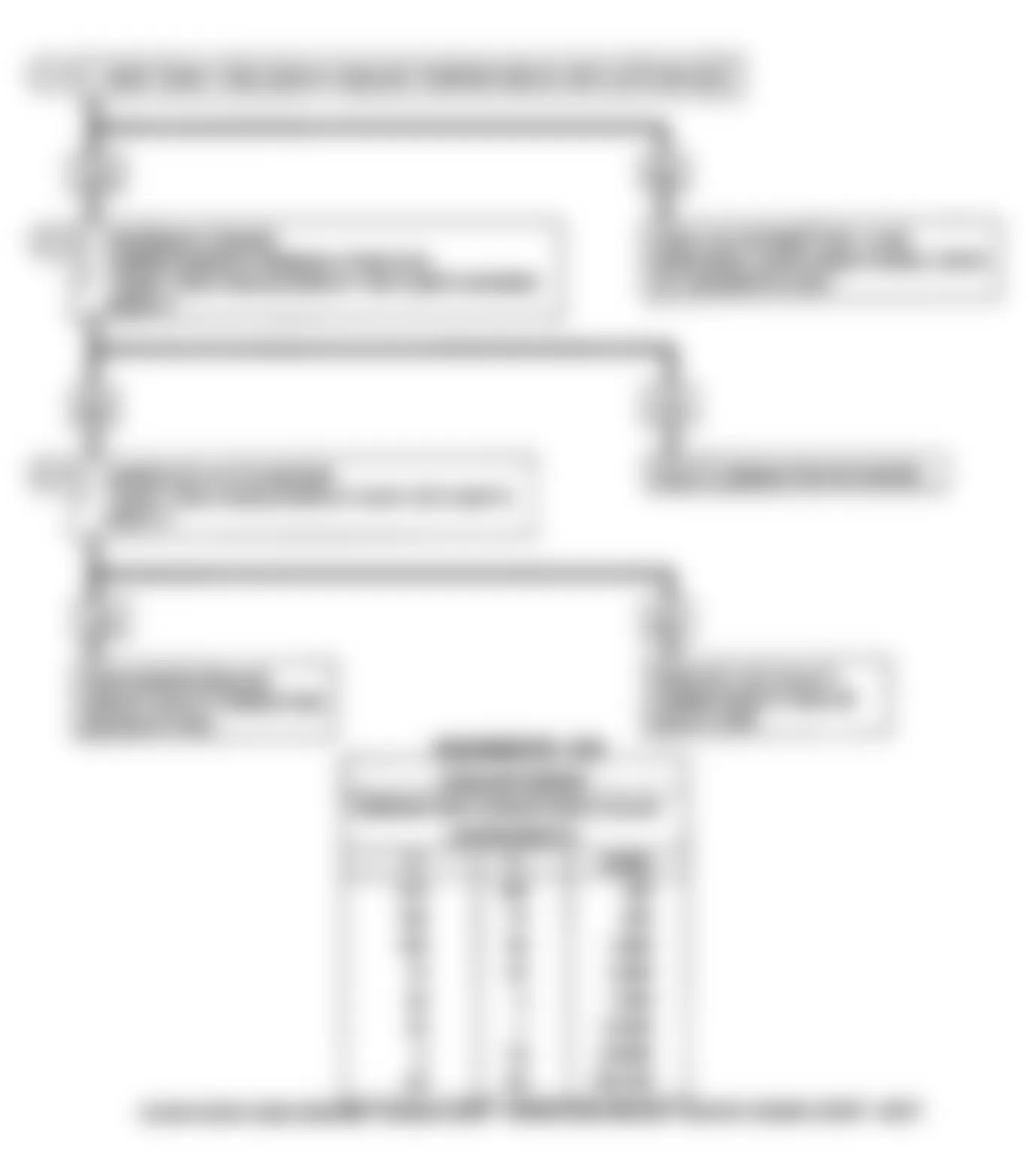
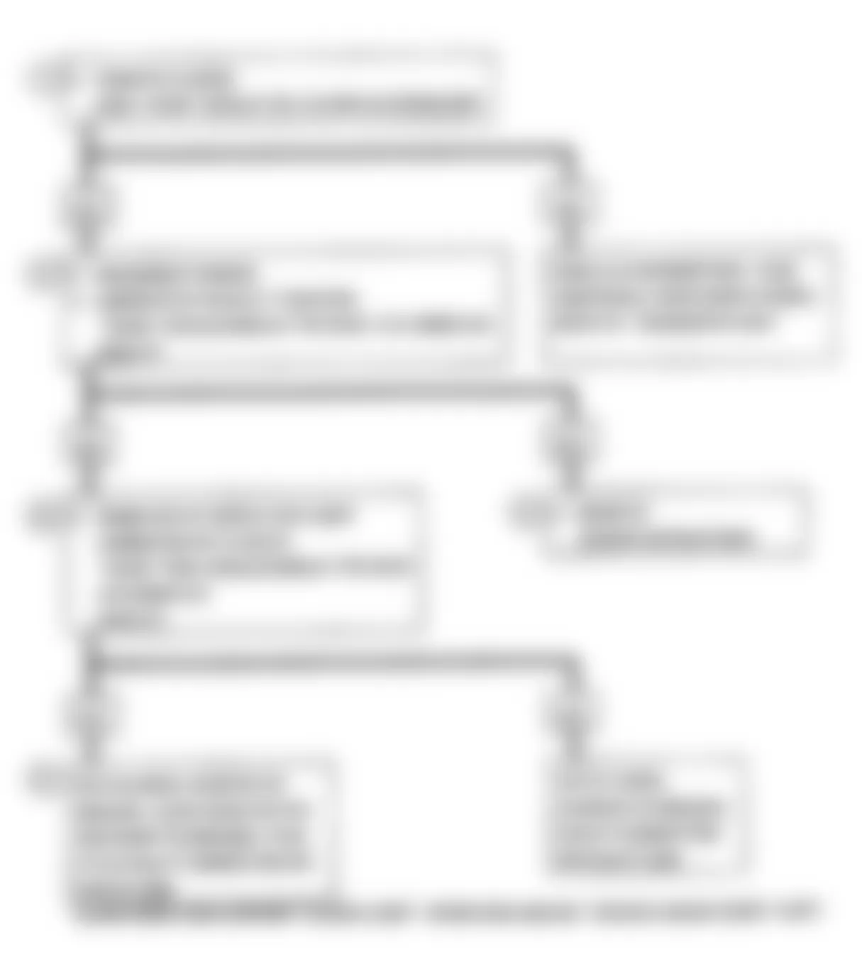
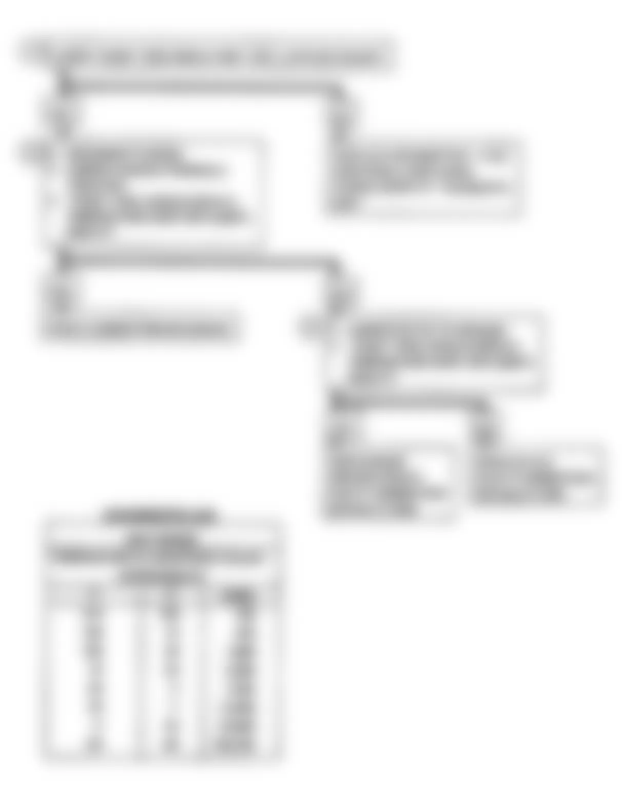
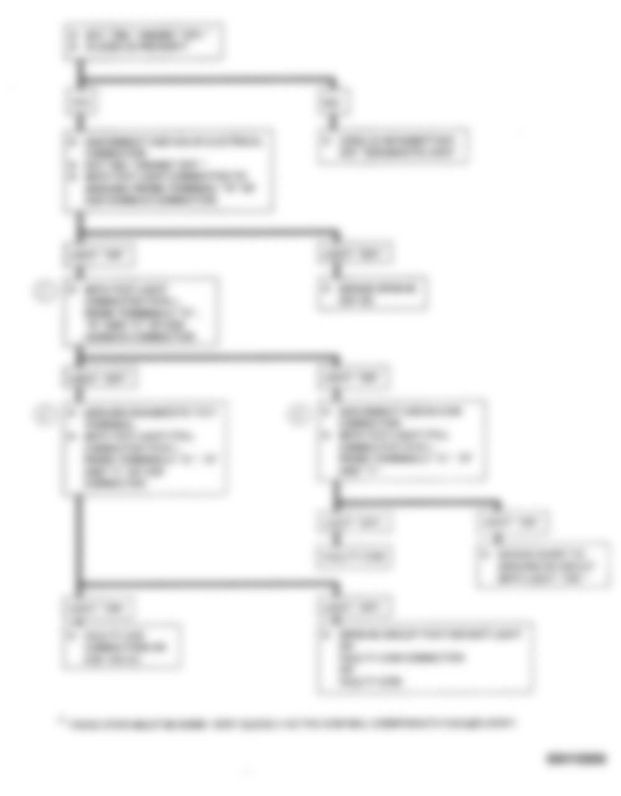
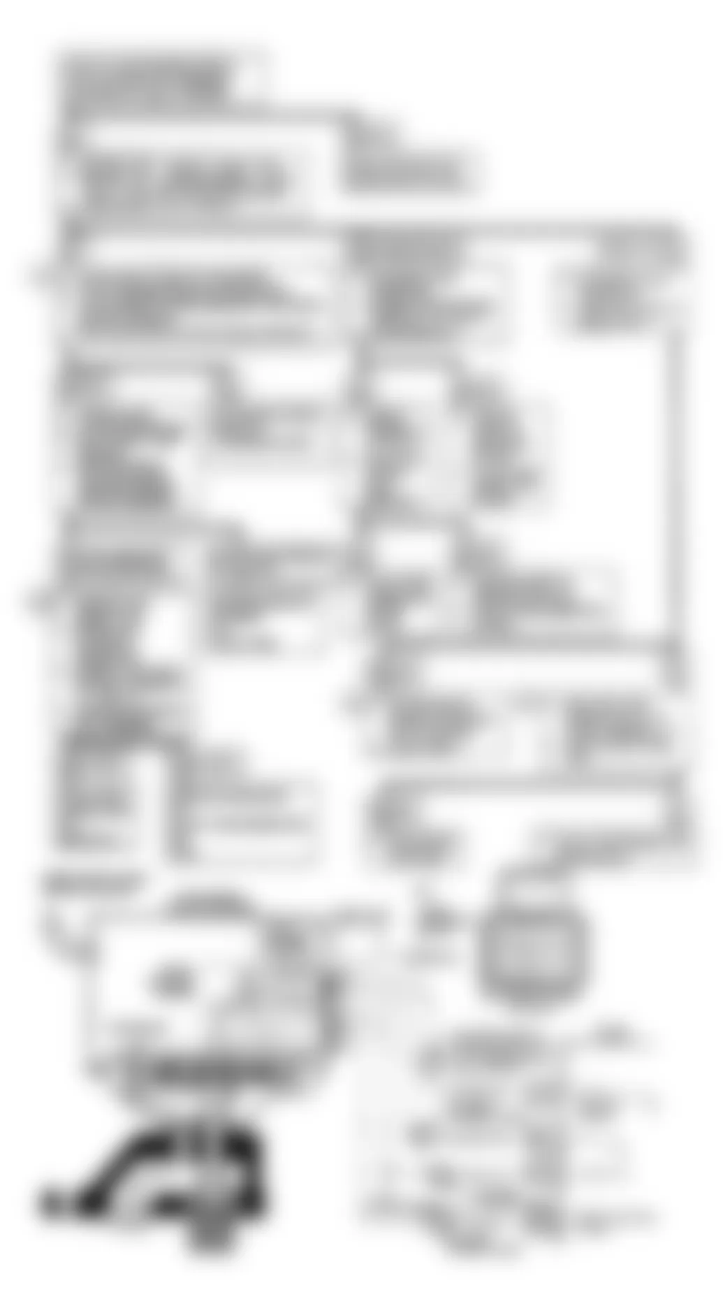
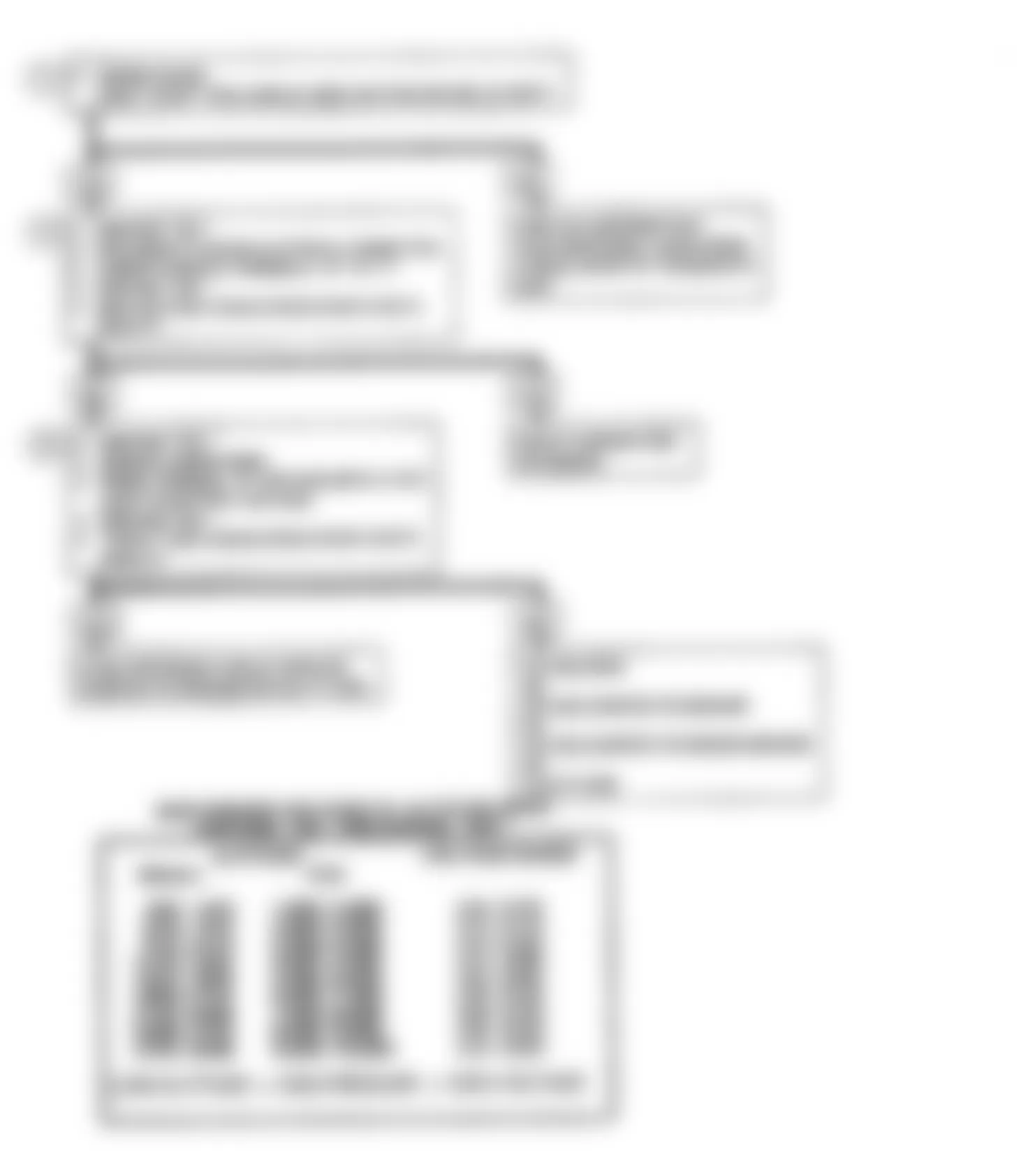
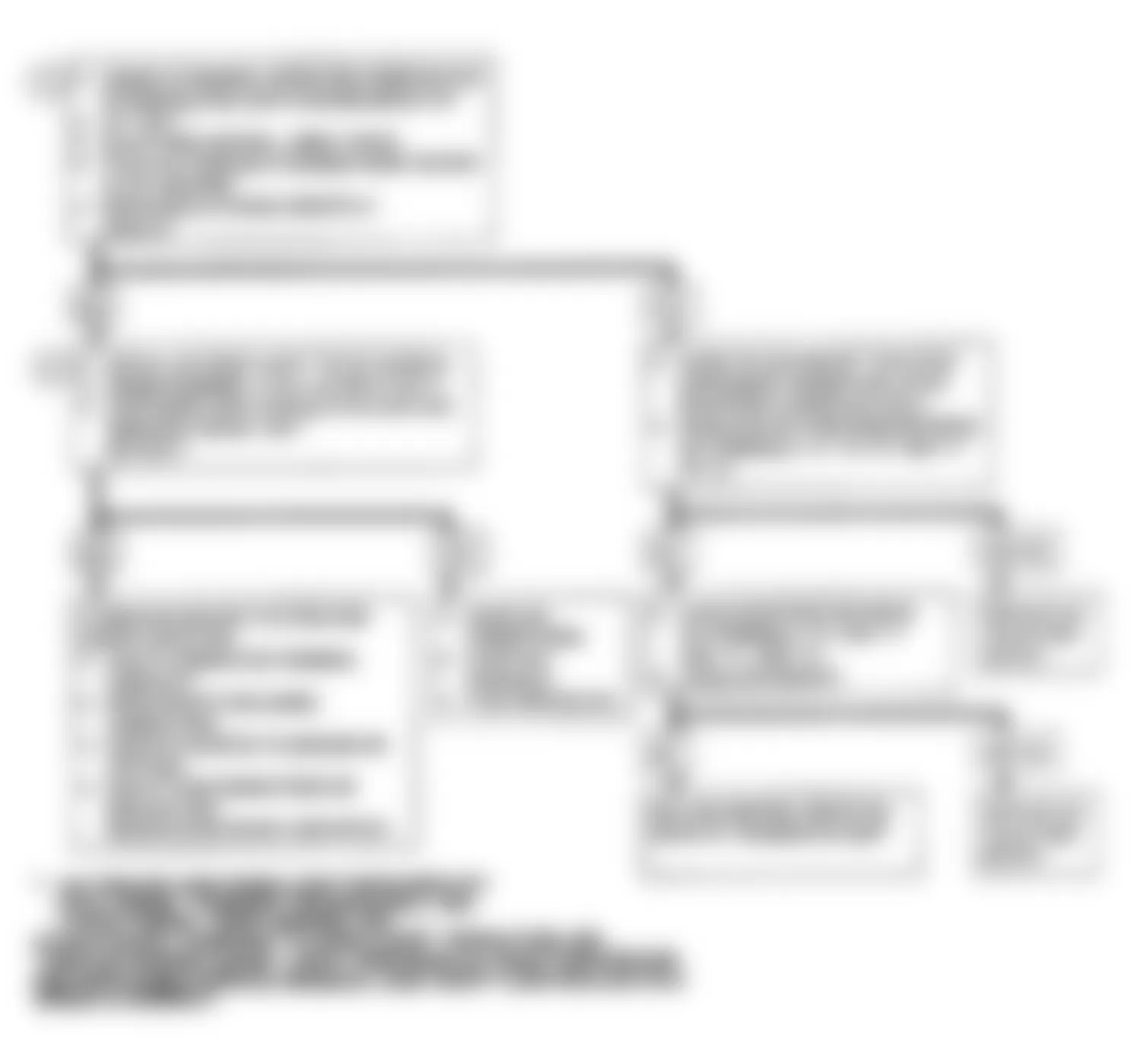
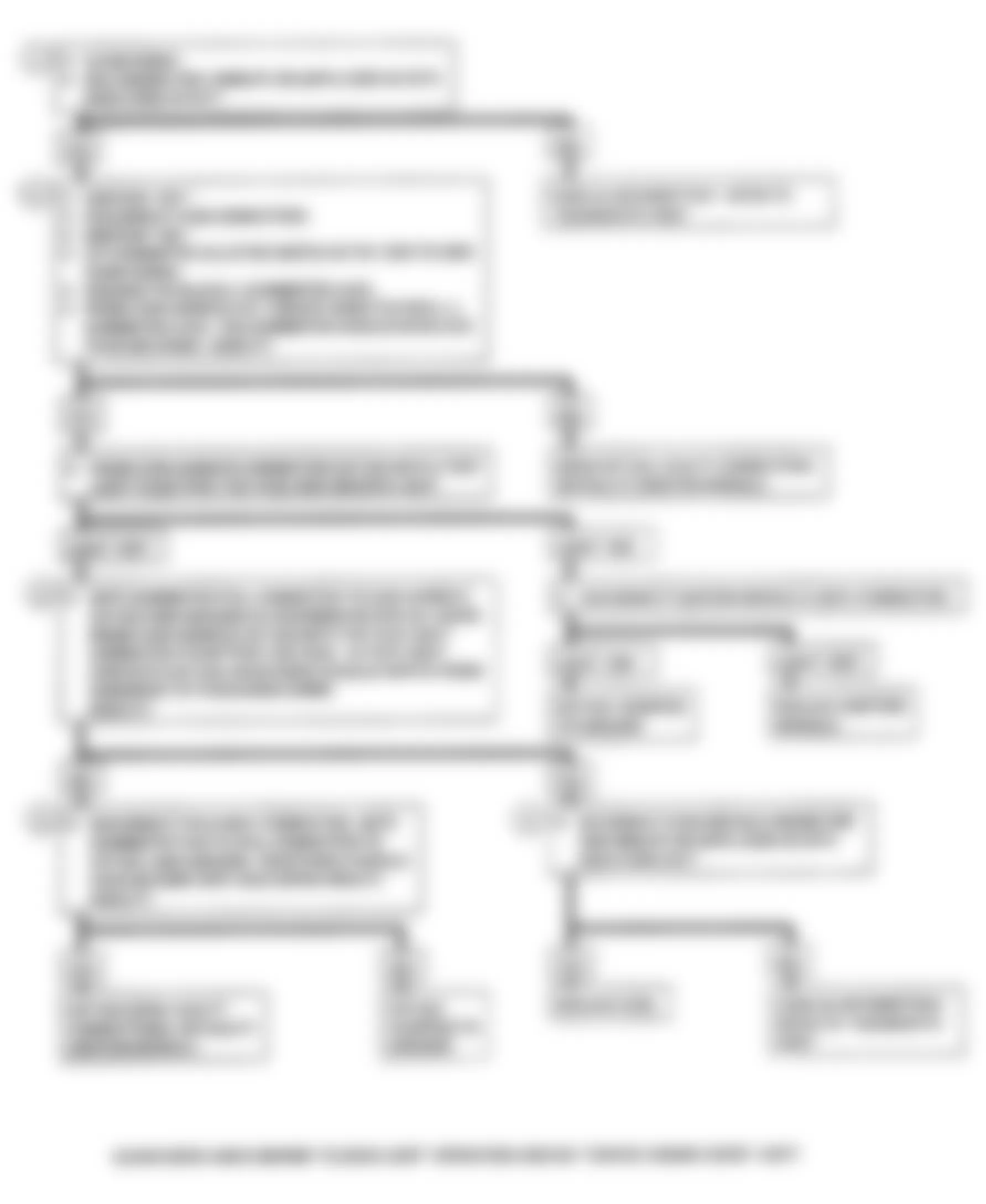
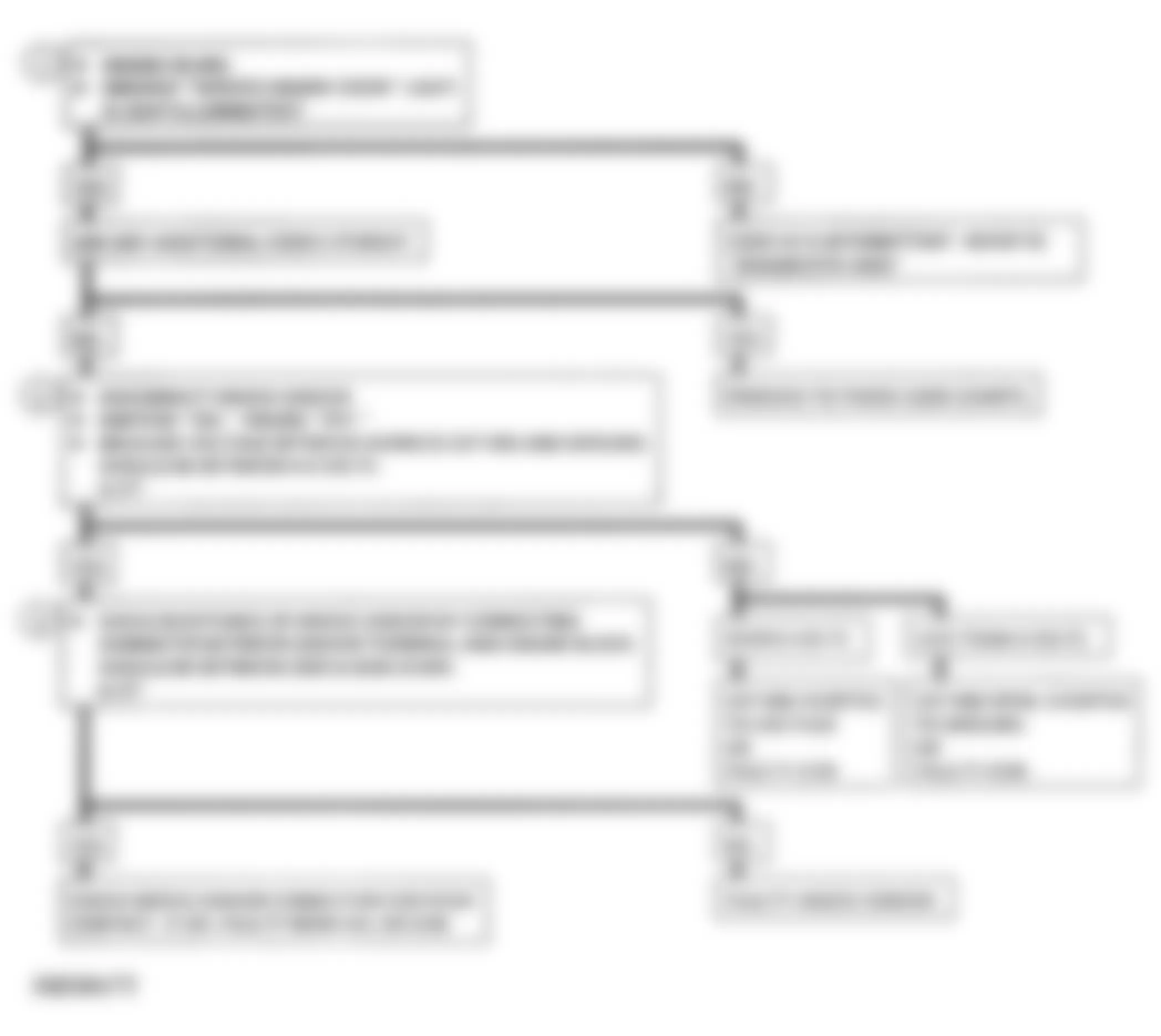
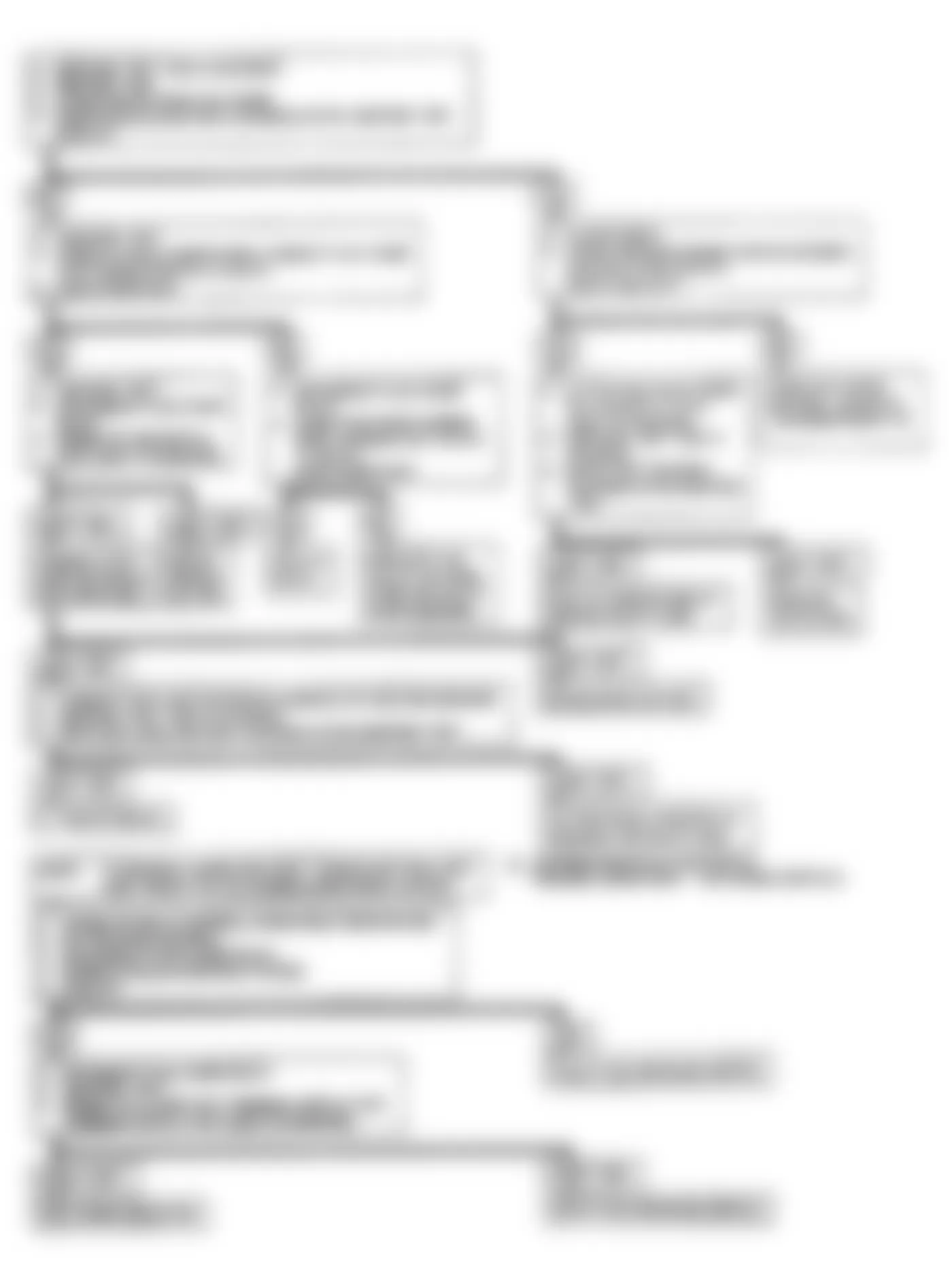
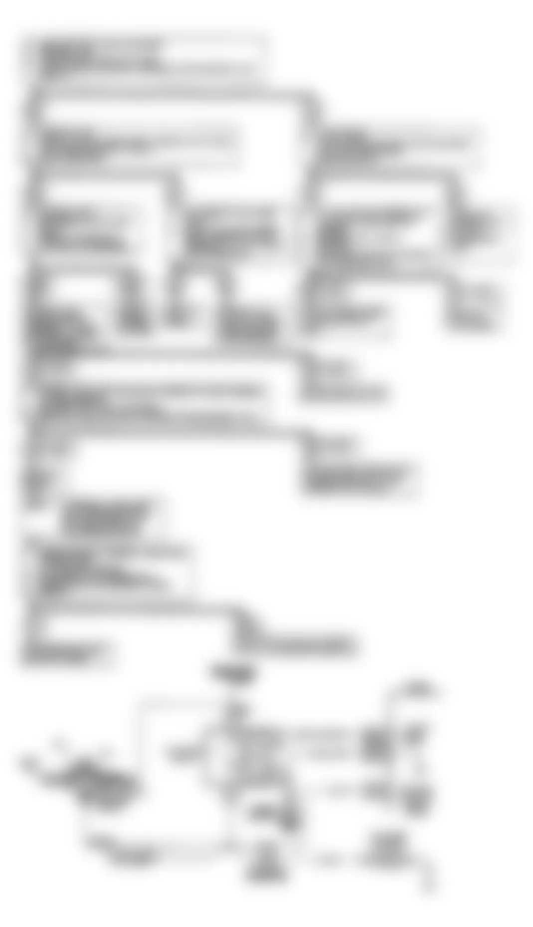
Fig. 5: Buick Regal Custom 1990 - Component Locations - Code 13: Open O2 Sensor Flow Chart
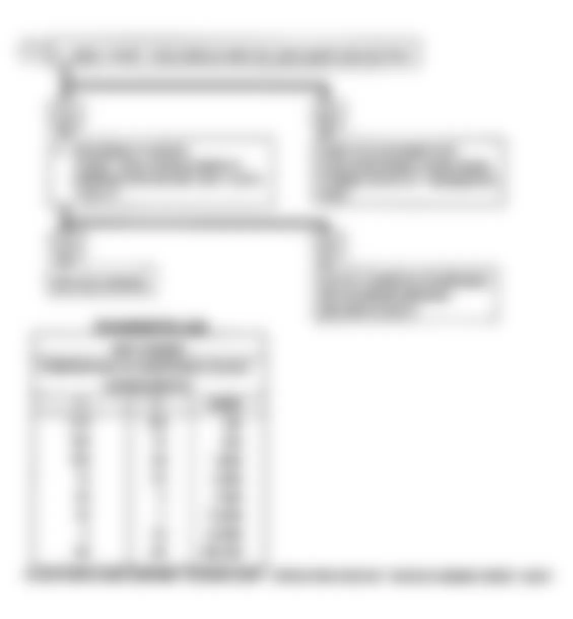
Buick Regal Custom 1990 - CODE 14: COOLANT TEMP SENSOR (CTS) SIGNAL VOLTAGE LOW
Coolant temperature is one input the ECM uses to control fuel delivery, spark timing, idle speed, converter clutch, canister purge, air management (man. trans.), EGR and cooling fan.
NOTE: Test numbers refer to test numbers on diagnostic chart.
- Code 14 will set if signal voltage indicates high coolant temperature for 3-20 seconds.
- This test determines if circuit No. 410 is shorted to ground which will cause the conditions for Code 14.
Buick Regal Custom 1990 - Diagnostic Aids
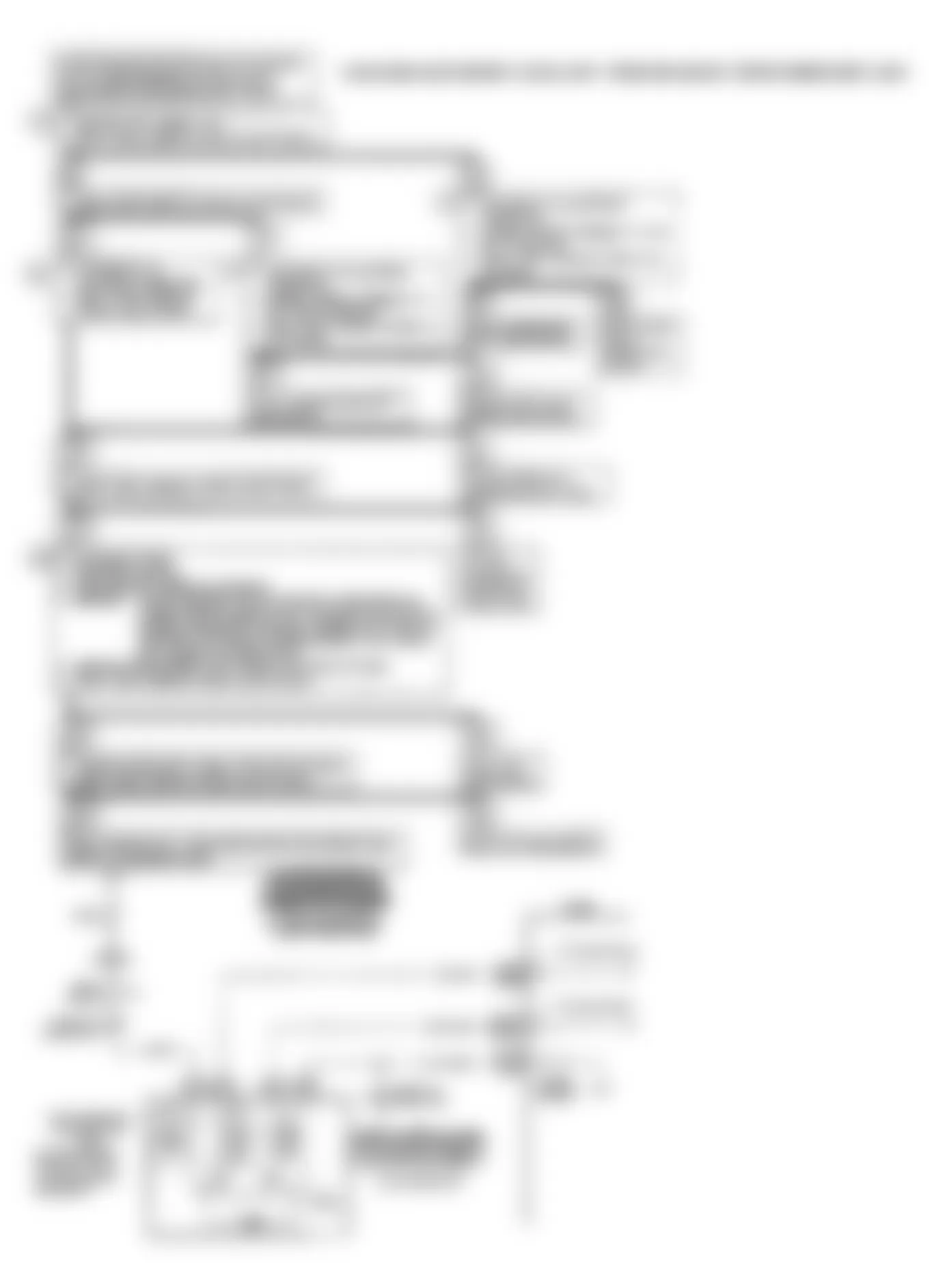
Check harness routing for a potential short to ground in circuit No. 410. The "Scan" tester displays engine temperature in degrees centigrade. After engine is started, the temperature should rise steadily to about 90?C, then stabilize when thermostat opens.
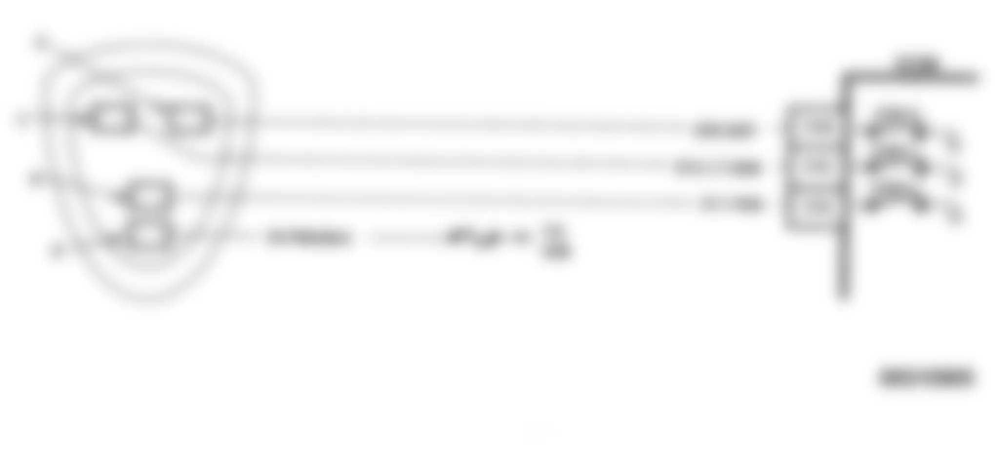
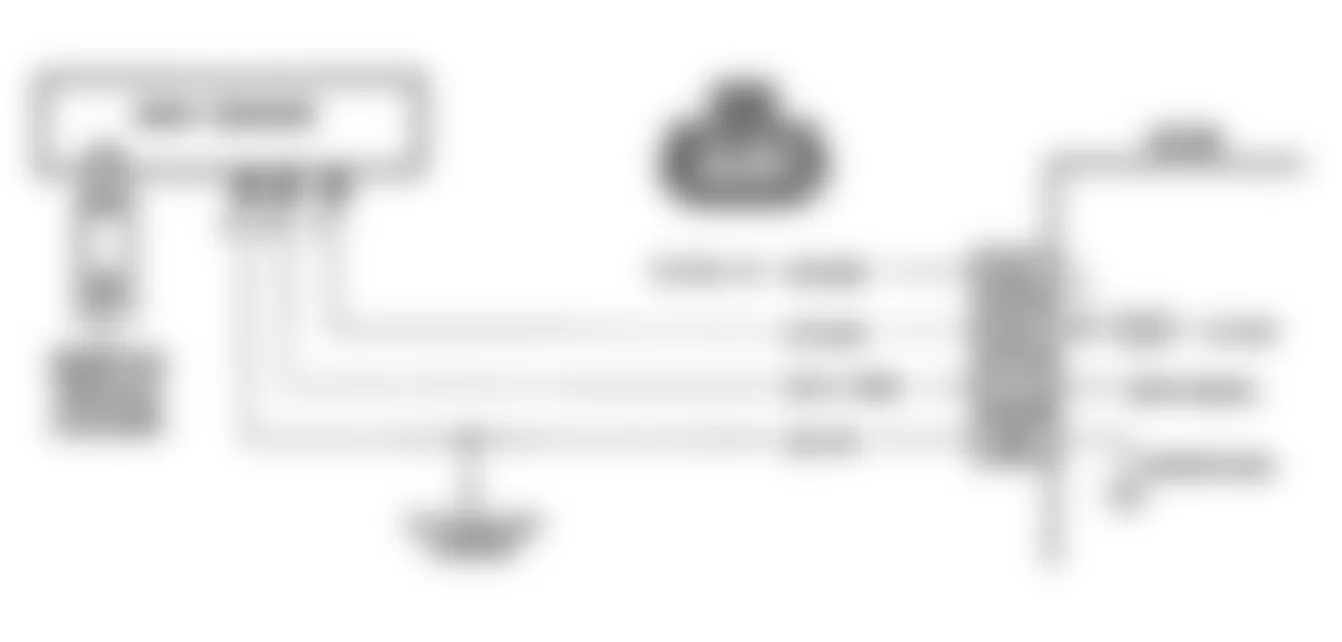
Fig. 6: Buick Regal Custom 1990 - Component Locations - Code 14: CTS Signal Low Schematic (A Body)
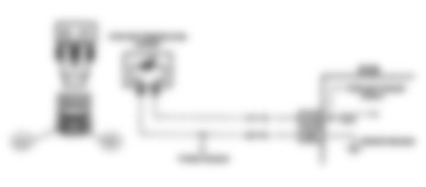
Fig. 7: Buick Regal Custom 1990 - Component Locations - Code 14: CTS Signal Low Schematic (F Body)
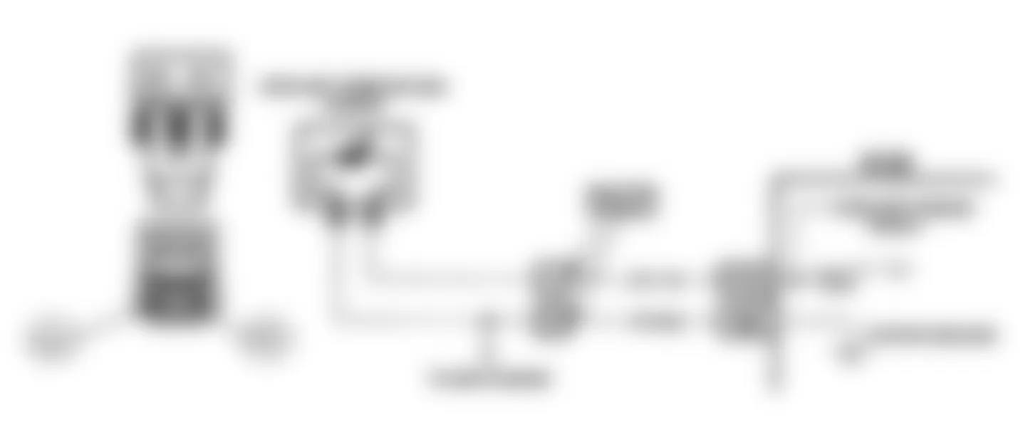
Fig. 8: Buick Regal Custom 1990 - Component Locations - Code 14: CTS Signal Low Schematic (J Body)

Fig. 9: Buick Regal Custom 1990 - Component Locations - Code 14: CTS Signal Low Schematic (L Body)
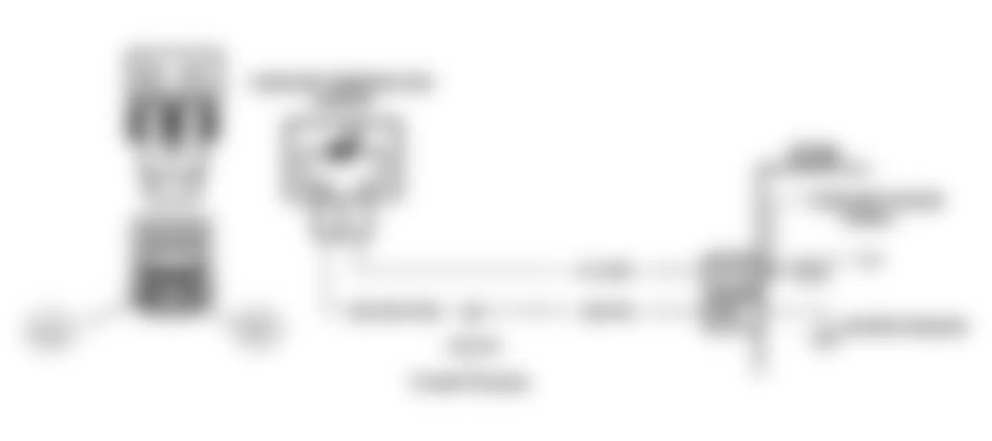
Fig. 10: Buick Regal Custom 1990 - Component Locations - Code 14: CTS Signal Low Schematic (W Body)

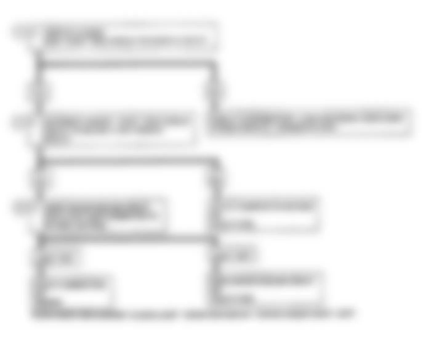
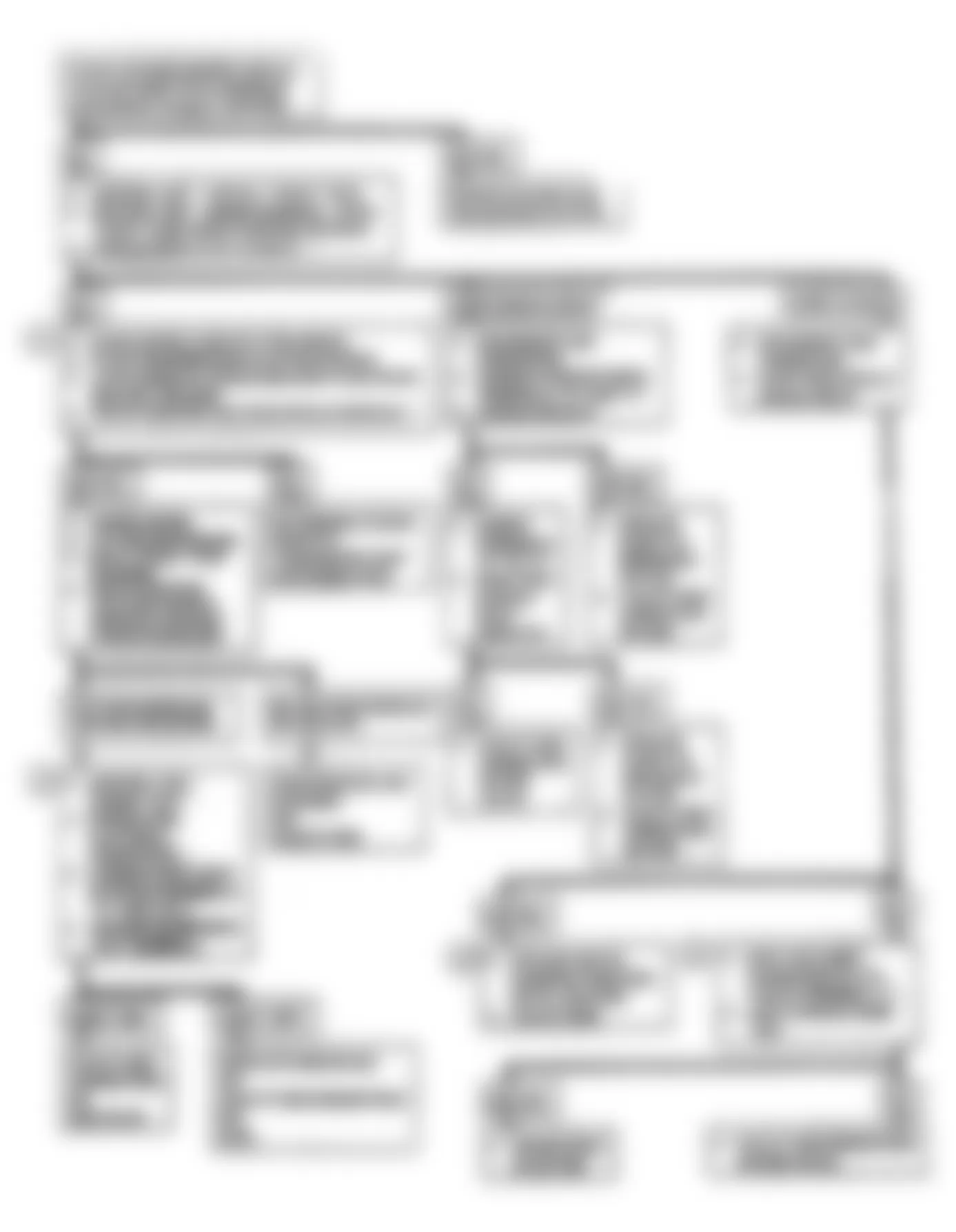
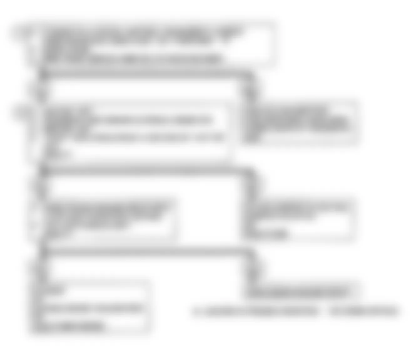
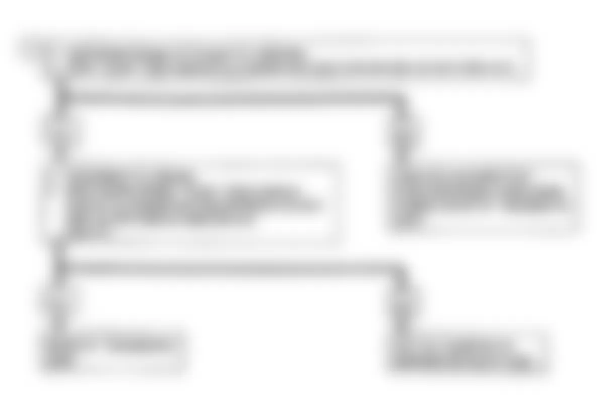
Fig. 11: Buick Regal Custom 1990 - Component Locations - Code 14: CTS Signal Voltage Low Flow Chart

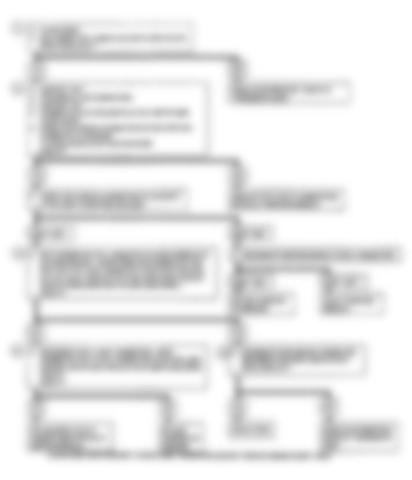
Buick Regal Custom 1990 - CODE 15: COOLANT TEMP SENSOR (CTS) SIGNAL VOLTAGE HIGH
Coolant temperature is one input the ECM uses to control fuel delivery, spark timing, idle speed, converter clutch, canister purge, air management (M/T), EGR and cooling fan.
NOTE: Test numbers refer to test numbers on diagnostic chart.
- Code 15 will set if signal voltage indicates coolant temperature is low for 3 seconds.
- This test simulates a Code 14. If the ECM recognizes the low signal voltage and the "Scan" tester reads 130?C or more, ECM and wiring are okay.
- This test determines if circuit No. 410 is open. There should be 5 volts present at sensor connector if measured with a digital volt-ohmmeter.
Buick Regal Custom 1990 - Diagnostic Aids
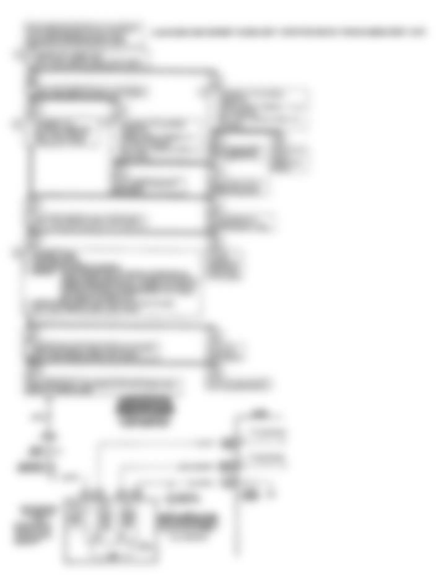
The "Scan" tester reads engine temperature in degrees centigrade. After engine is started, the temperature should rise steadily to about 90?C, then stabilize when thermostat opens.
A faulty connection or an open in either circuit will result in a Code 15. If Code 21, 23 or 33 is also set, check ground circuit for faulty wiring or connections. Check terminals at sensor for a good contact.
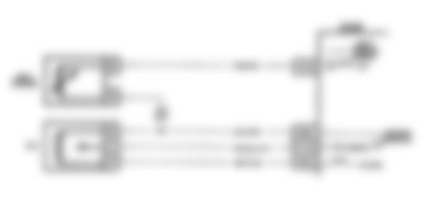
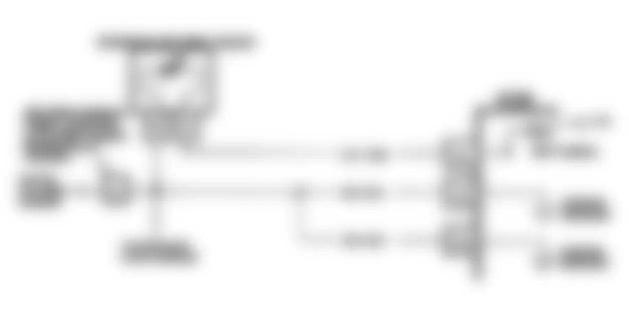
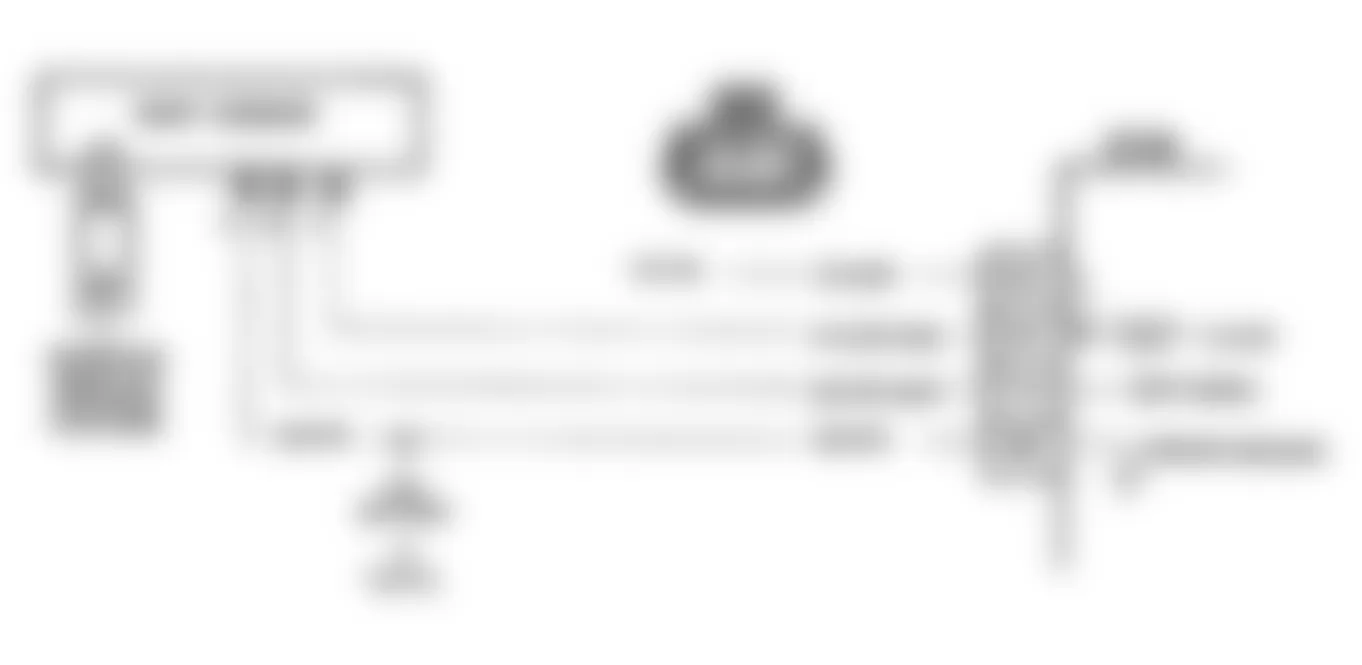
Fig. 12: Buick Regal Custom 1990 - Component Locations - Code 15: CTS Signal High Schematic (A Body)

Fig. 13: Buick Regal Custom 1990 - Component Locations - Code 15: CTS Signal High Schematic (F Body)

Fig. 14: Buick Regal Custom 1990 - Component Locations - Code 15: CTS Signal High Schematic (J Body)
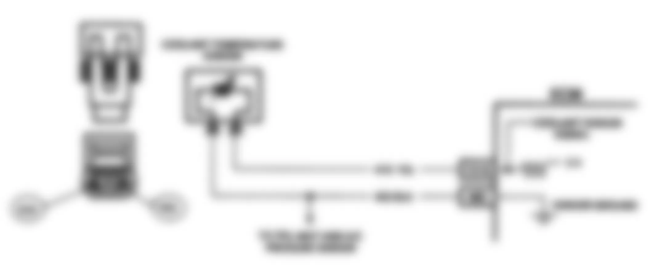
Fig. 15: Buick Regal Custom 1990 - Component Locations - Code 15: CTS Signal High Schematic (L Body)

Fig. 16: Buick Regal Custom 1990 - Component Locations - Code 15: CTS Signal High Schematic (W Body)

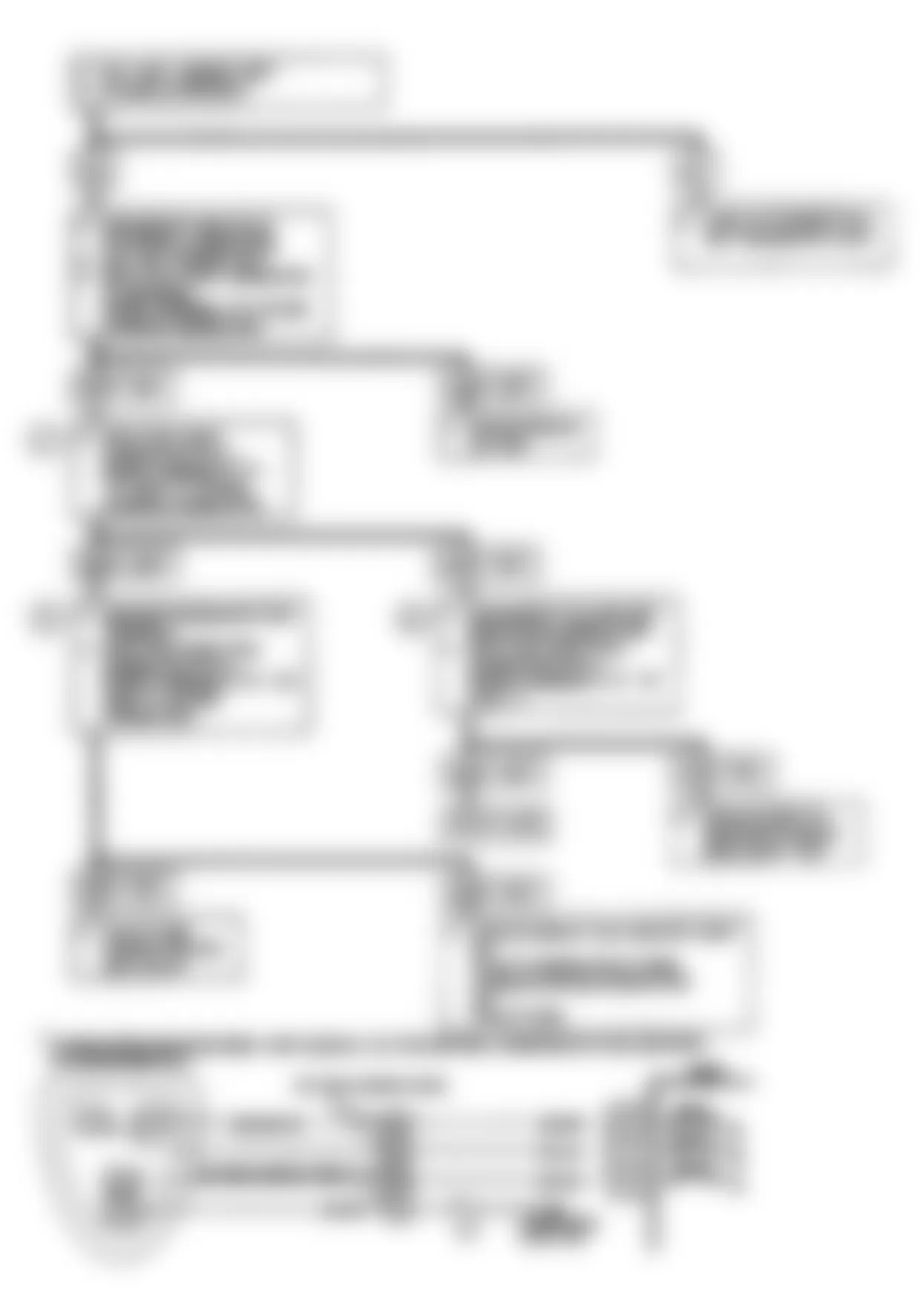
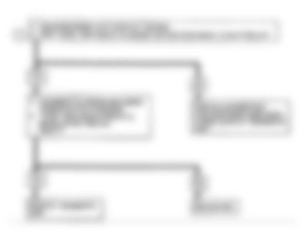
Fig. 17: Buick Regal Custom 1990 - Component Locations - Code 15: CTS Signal Voltage High Flow Chart
Buick Regal Custom 1990 - CODE 21: TPS SIGNAL VOLTAGE HIGH
NOTE: Test numbers refer to test numbers on diagnostic chart.
- Code 21 will set if TPS is greater than 4.5 volts with ignition on or if the engine is running, TPS voltage is high, airflow is low and all 3 conditions have existed for 3-10 seconds. This step confirms Code 21 is present.
- With TPS sensor disconnected, the TPS voltage should go low if the ECM and wiring are okay.
- Probing the ground circuit with a test light to battery voltage checks the 5-volt return circuit. A faulty 5-volt return will cause a Code 21.
Buick Regal Custom 1990 - Diagnostic Aids
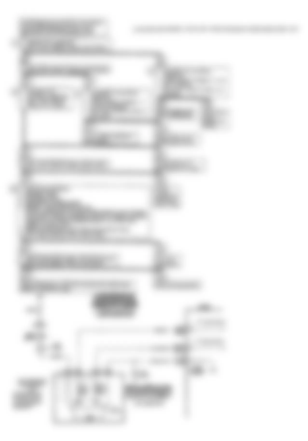
The "Scan" tester reads throttle position in volts. Reading should be low with throttle closed and ignition on or at idle. Voltage should increase at a steady rate as throttle is moved toward wide open. An open in circuit No. 452 will result in a Code 21. Some "Scan" testers measure throttle angle as a percent. A fully closed throttle should read zero percent and a wide open throttle should read 100 percent.

Fig. 19: Buick Regal Custom 1990 - Component Locations - Code 21: TPS Signal High Schematic (F Body)

Fig. 20: Buick Regal Custom 1990 - Component Locations - Code 21: TPS Signal High Schematic (W Body)
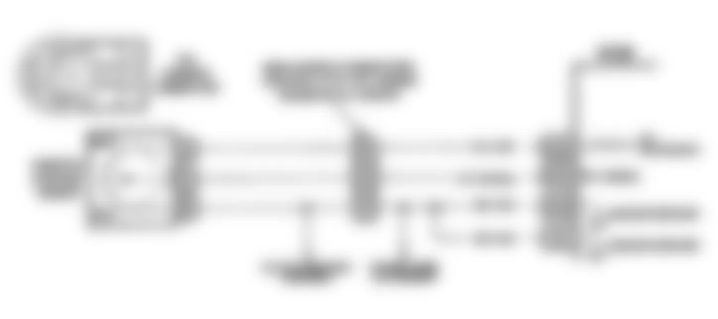
Fig. 21: Buick Regal Custom 1990 - Component Locations - Code 21: TPS Signal Voltage High Flow Chart
Buick Regal Custom 1990 - CODE 22: TPS SIGNAL VOLTAGE LOW
- Code 22 will set if TPS signal voltage is less than about .2 volt for 3 seconds and the engine running. This test confirms Code 22 is present.
- Simulates Code 21. If the ECM recognizes the high signal voltage and sets Code 21, the ECM and wiring are okay.
- With throttle closed, the TPS voltage reading should be at idle specification. See DIAGNOSTIC AIDS.
- This simulates a high signal voltage to check for an open in circuit No. 417.
- On some models a buffered 5-volt throttle position sensor reference circuit is shared by the MAP sensor. If either of these circuits is shorted to ground, a Code 22 will set. To determine if the MAP sensor is causing the Code 22, disconnect the MAP sensor and see if Code 22 is reset.
Buick Regal Custom 1990 - Diagnostic Aids
The "Scan" tester reads throttle position in volts. Reading should be low with throttle closed and ignition on or at idle. Voltage should increase at a steady rate as throttle is moved toward wide open. An open in circuit No. 452 will result in a Code 21. Some "Scan" testers measure throttle angle as a percent. A fully closed throttle should read zero percent and a wide open throttle should read 100 percent.
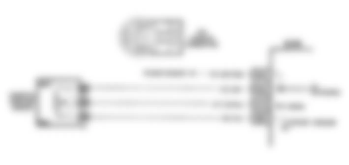
Fig. 23: Buick Regal Custom 1990 - Component Locations - Code 22: TPS Signal Low Schematic (F Body)
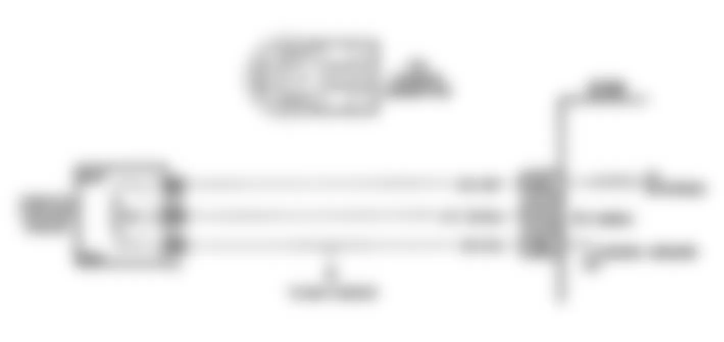
Fig. 24: Buick Regal Custom 1990 - Component Locations - Code 22: TPS Signal Low Schematic (W Body)

Fig. 25: Buick Regal Custom 1990 - Component Locations - Code 22: TPS Signal Voltage Low Flow Chart
Buick Regal Custom 1990 - CODE 23: MAT SENSOR SIGNAL VOLTAGE HIGH
- Code 23 will set within 4-8 minutes if signal voltage indicates manifold air temperature is low for 3-12 seconds and no vehicle speed signal is present (vehicle not moving). Due to the conditions necessary to set a Code 23, the SERVICE ENGINE SOON light will only stay on when all conditions are met.
- A Code 23 will set due to an open sensor, wire or connection. This test determines if the wiring and ECM are okay. The MAT sensor is difficult to reach on some models so this test can be performed at the MAT sensor harness connector.
- This determines if an open is present in sensor signal or ground circuit.
Buick Regal Custom 1990 - Diagnostic Aids
The "Scan" tester reads temperature of the air entering the engine. Temperature should read close to ambient air temperature when engine is cold and should rise as underhood temperature increases. Carefully check harness and connections for possible open in sensor circuits. Use the TEMPERATURE-TO-RESISTANCE VALUES table to help determine if sensor calibration has shifted.


Buick Regal Custom 1990 - CODE 24: VEHICLE SPEED SENSOR
The ECM monitors Permanent Magnet (PM) generator output on circuits No. 400 and 401. The PM generator, mounted in the transaxle, produces a pulsating, alternating current whenever vehicle speed is greater than 3 MPH. The AC voltage level and number of pulses increases with vehicle speed. The ECM will calculate vehicle speed based on time between pulses. The VSS buffer, used on other models, is incorporated into the ECM on these models.
If the vehicle is equipped with a digital speedometer and odometer and/or cruise control, ECM provides pulses for operation of these components (2000 and 4000 pulses per mile, respectively). The "Scan" tester reading should closely match speedometer reading when drive wheels are turning.
NOTE: Test numbers refer to test numbers on diagnostic chart.
- Code 24 will set if vehicle speed equals zero MPH when engine speed is between 1400 and 3600 RPM, throttle opening is less than 2 percent, a low load condition exists and transmission is not in Park or Neutral. All conditions must be met for 5-10 seconds during a road load deceleration. Disregard Code 24 that sets when drive wheels are not turning.
Buick Regal Custom 1990 - Diagnostic Aids
If "Scan" tester displays vehicle speed, check Park/Neutral switch operation. See the SYSTEM/COMPONENT TESTS article. If switch is okay, check for intermittent connections. Also, check for proper application of PROM or MEM-CAL.
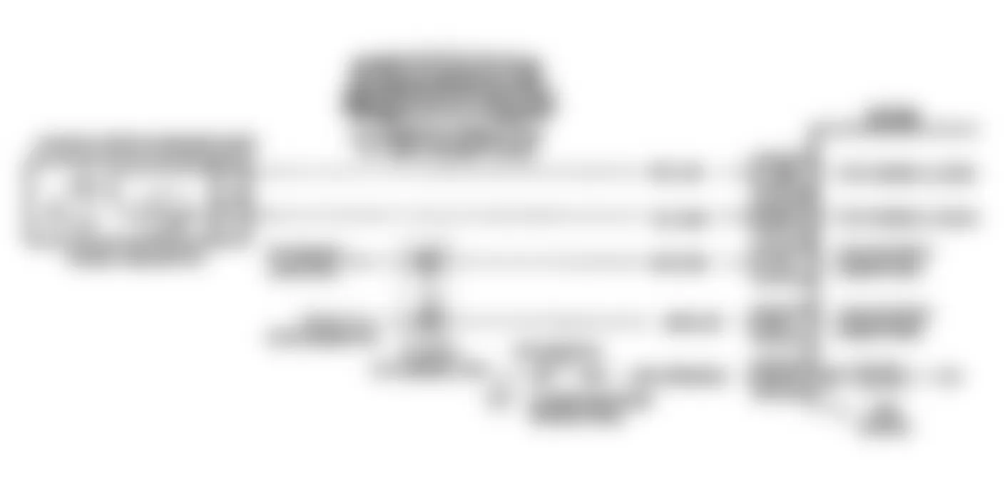

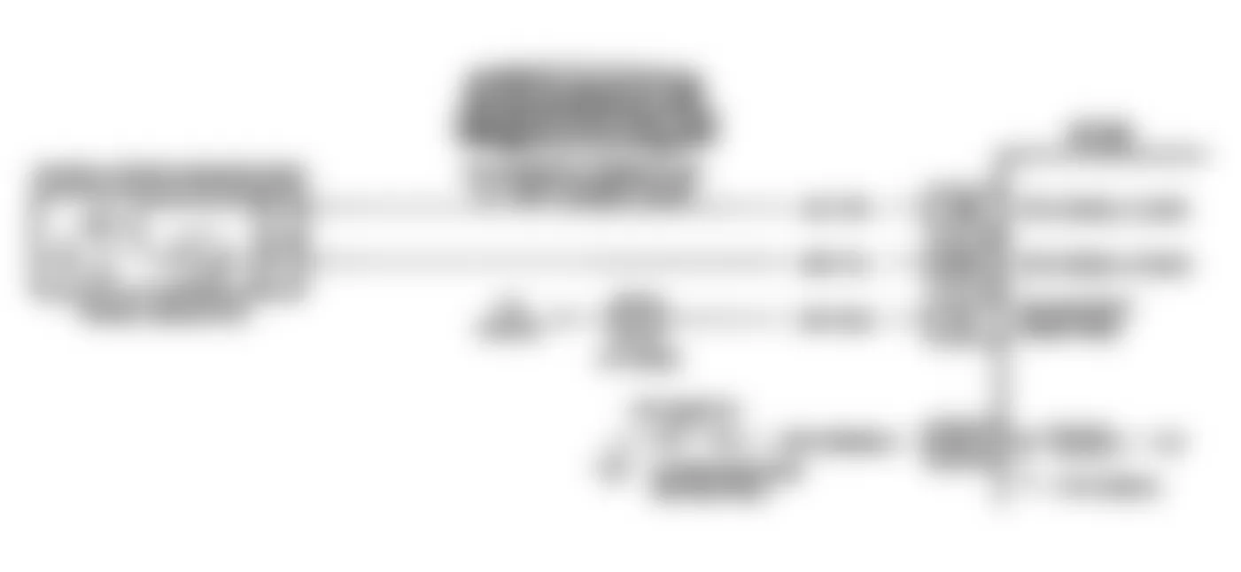
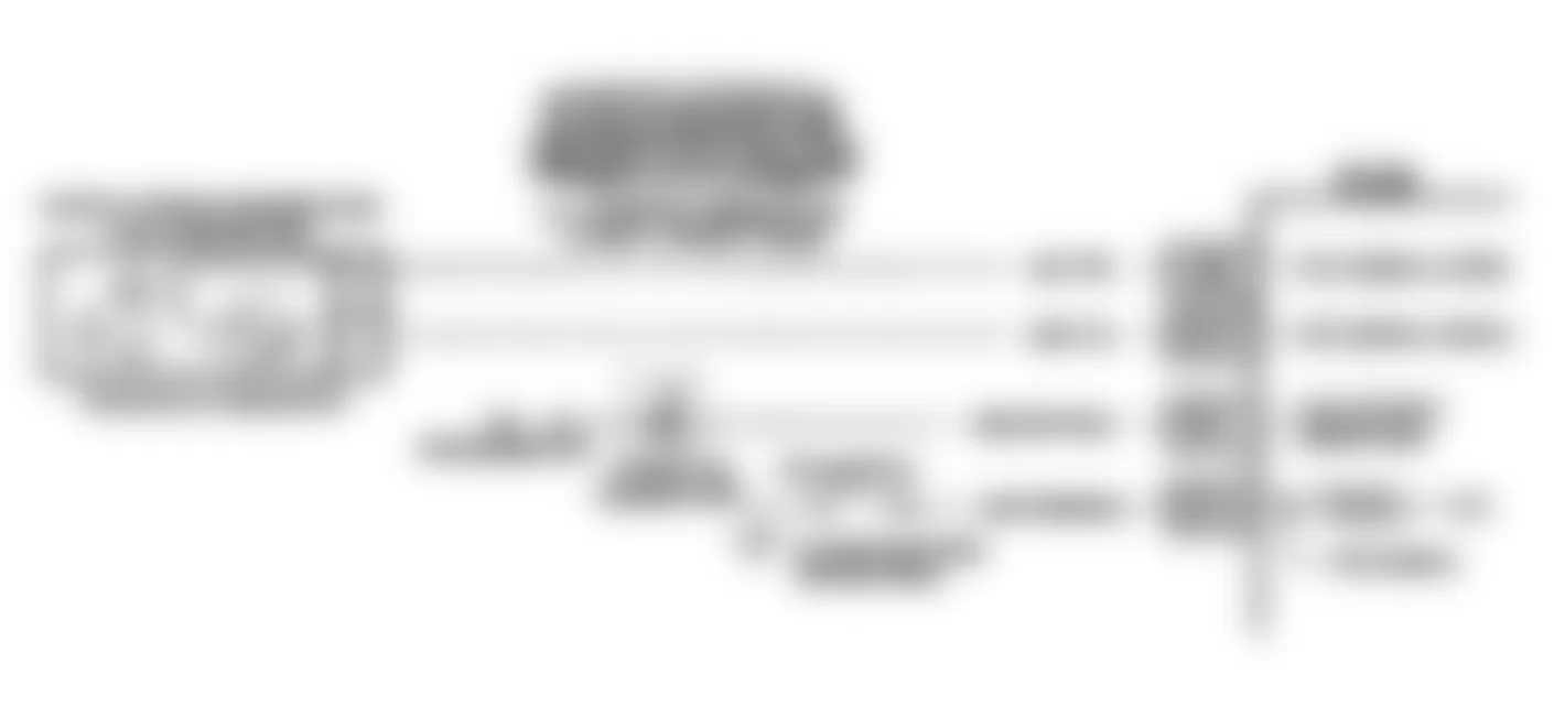

Fig. 36: Buick Regal Custom 1990 - Component Locations - Code 24: Vehicle Speed Sensor Flow Chart
Buick Regal Custom 1990 - CODE 25: MAT SIGNAL VOLTAGE LOW
NOTE: Test numbers refer to test numbers on diagnostic chart.
- Code 25 will set if monitored voltage indicates manifold air temperature is high for 3 seconds and time since engine start is at least 3-8 minutes, depending upon engine application. Due to the conditions necessary to set a Code 25, the "SERVICE ENGINE SOON" light will remain on only while the signal is low and vehicle speed is present.
Buick Regal Custom 1990 - Diagnostic Aids
The "Scan" tester reads temperature of the air entering the engine. Parameter should read close to ambient air temperature when engine is cold, and rise as underhood temperature increases. A short to ground in the MAT signal line will result in a Code 25. Use the TEMPERATURE VS. RESISTANCE VALUES table in flow chart to determine if sensor calibration has shifted.

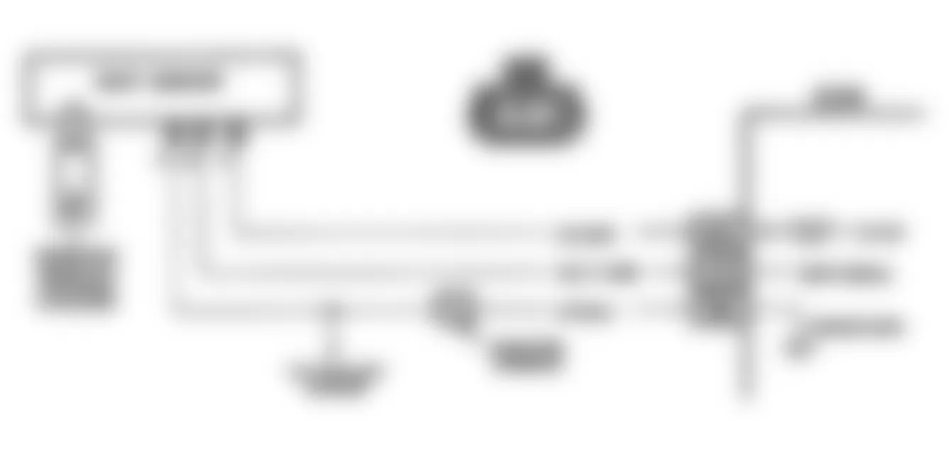
Fig. 38: Buick Regal Custom 1990 - Component Locations - Code 25: MAT Signal Low Schematic (J Body)

Fig. 39: Buick Regal Custom 1990 - Component Locations - Code 25: MAT Signal Low Schematic (L Body)

Fig. 40: Buick Regal Custom 1990 - Component Locations - Code 25: MAT Signal Low Schematic (W Body)
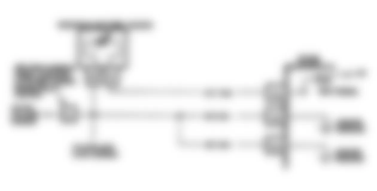
Fig. 41: Buick Regal Custom 1990 - Component Locations - Code 25: MAT Signal Voltage Low Flow Chart
Buick Regal Custom 1990 - CODE 31: WASTEGATE OVERBOOST (W BODY TURBO)
- Code 31 will set when the manifold pressure is greater than 20 psi (1.4 kg/cm2 ) of boost for 2 seconds and Code 33 has not been previously set. Code 31 will set and the "SERVICE ENGINE SOON" light will stay on only while overboost exists. The light will stay on for 10 seconds after the condition stops and then go off. An overboost condition could be caused by a short to ground in circuit No. 999, a sticking wastegate actuator or wastegate, a control valve stuck in the closed position, a cut or pinched hose, or a faulty ECM. An underboost condition could be caused by a wastegate actuator or wastegate sticking open, no ignition feed to control valve or an open wire to ECM, or a faulty ECM. If an overboost condition exists (as indicated by MAP sensor), ECM will reduce fuel delivery to prevent damage to engine. With ignition off, the control valve solenoid is open and should allow pressure to wastegate actuator. Also check for an extremely dirty air filter.
- After pressure is applied to valve and the pressure source is removed, actuator should slowly move back and close wastegate. If pressure does not bleed off, vent in the control valve solenoid could be plugged.
- With key on and diagnostic terminal not grounded, control valve solenoid should not be energized. This should allow vacuum to pass through solenoid, opening actuator.
- With key on and the solenoid activated with the Tech 1, control valve solenoid should be energized. This closes off manifold vacuum to wastegate actuator.
- This tests electrical control portion of the system. With ignition on and engine not running, and solenoid energized by the Tech 1, solenoid circuit should be energized.
- Circuit No. 250 is the main feed for the wastegate solenoid. It is powered by a 10-amp fuse, located in the left side engine electrical center. If fuse is blown, replace it. If it blows again, locate short to ground in circuit No. 250.

Buick Regal Custom 1990 - CODE 32: EGR SYSTEM FAILURE (EXCEPT W BODY)
Code 32 represents an EGR flow test failure. The ECM will cycle the internal EGR solenoids on and off individually on closed throttle coast down. ECM monitors resulting changes in engine RPM and O2 sensor activity.
NOTE: Test numbers refer to test numbers on diagnostic chart.
- Determines if there is power to the EGR valve.
- Determines if there is an open circuit in the EGR wiring or if the EGR valve is faulty.
- Determines if there is a short to ground in any EGR valve circuit or if the ECM is faulty.
Buick Regal Custom 1990 - Diagnostic Aids
An intermittent may be caused by a poor connection, rubbed through wiring insulation, or a wire broken inside of the insulation. See INTERMITTENTS in TESTS W/O CODES article.
Buick Regal Custom 1990 - CODE 32: EGR SYSTEM FAILURE (W BODY TURBO)
The integrated electronic EGR valve is a sealed unit which functions similar to a port valve with a remote vacuum regulator. The internal solenoid is normally open, causing the vacuum signal to be vented to atmosphere. The EGR valve contains a built-in voltage regulator, which modifies ECM signals. This provides different EGR flow by regulating the current to the internal solenoid. The ECM controls EGR by varying a pulsed signal to turn on and off the EGR valve many times a second. This system also contains a pintle position sensor which works similar to a TPS. As EGR flow increases, pintle signal will increase. Code 32 will set if EGR pintle position does not match duty cycle or if coolant temperature is greater than a specified amount and no EGR signal is detected.
NOTE: Test numbers refer to test numbers on diagnostic chart.
- With the engine running, transmission in gear and brakes applied, increasing engine speed will put a load on the engine. Engine vacuum will be applied to the EGR diaphragm and cause the EGR pintle valve to open, increasing pintle position voltage.
- Grounding the ALDL test terminal should energize the solenoid, which closes off the vent and allows vacuum to move the diaphragm. This test determines if the ECM is capable of controlling the solenoid. When EGR is commanded on by the ECM, the test light should be on.
- If circuit No. 450 is open, pintle signal will go high (5-volt signal). This will set Code 32. If circuit No. 357 becomes shorted to 12 volts or to circuit No. 416, the signal voltage will go high, causing Code 32.
Buick Regal Custom 1990 - Diagnostic Aids
Some "Scan" testers show pintle position in volts. The EGR position voltage can determine if the pintle is moving. When no EGR is commanded, the position sensor should read about .5-1.5 volts. Voltage should increase with the commanded EGR duty cycle. If system operates as indicated, trouble code is intermittent. See the INTERMITTENTS procedures in the TESTS W/O CODES article.
Buick Regal Custom 1990 - CODE 32: EGR SYSTEM FAILURE (W BODY NON-TURBO)
Code 32 represents an EGR flow test failure. The ECM will cycle the internal EGR solenoids on and off individually on closed throttle coast down. ECM monitors resulting changes in MAP sensor signal. If a calibrated response is not seen in MAP sensor signal, Code 32 will set.
NOTE: Test numbers refer to test numbers on diagnostic chart.
- Determines if there is power to the EGR valve.
- Determines if there is an open circuit in the EGR wiring or if EGR valve is faulty.
- Determines if there is a short to ground in any circuit going to the EGR valve or if ECM is faulty.
Buick Regal Custom 1990 - Diagnostic Aids
An intermittent may be caused by a poor connection, rubbed through wiring insulation or a wire broken inside of the insulation. See INTERMITTENTS in TESTS W/O CODES article.
Buick Regal Custom 1990 - CODE 33: MAP SENSOR SIGNAL VOLTAGE HIGH
- Code 33 will set the following conditions are met:
- Engine running.
- Manifold pressure is greater than specified.
- Throttle angle is less than 2 percent.
- All conditions have been met for 1-5 seconds.
Engine misfire or a low, unstable idle may set a Code 33.
- With the MAP sensor disconnected, the ECM should recognize a low voltage. If low voltage is shown on "Scan" tester, ECM and harness are not at fault.
Buick Regal Custom 1990 - Diagnostic Aids
If MAP sensor is disconnected, ECM will go into back-up MAP mode. An open ground circuit will set a Code 33. If idle is rough or unstable, refer to SYMPTOMS in TESTS W/O CODES article in this section to help determine if idle problem is causing Code 33.


Buick Regal Custom 1990 IGNITION ON - ENGINE STOPPED MAP VOLTAGES (1)
Altitude - Meters Altitude - Feet Voltage Range - Volts DC Below 305 Below 1,000 3.8-5.5 305-610 1,000-2,000 3.6-5.3 610-914 2,000-3,000 3.5-5.1 14-1,219 3,000-4,000 3.3-5.0 1,219-1,524 4,000-5,000 3.2-4.8 1,524-1,829 5,000-6,000 3.0-4.6 1,829-2,133 6,000-7,000 2.9-4.5 2,133-2,438 7,000-8,000 2.8-4.3 2,438-2,743 8,000-9,000 2.6-4.2 2,743-3,048 9,000-10,000 2.5-4.0
(1) Low Altitude = High Pressure = High Voltage
Buick Regal Custom 1990 - CODE 34: MAP SIGNAL VOLTAGE LOW
NOTE: Test numbers refer to test numbers on diagnostic chart. Turn ignition off for 10 seconds before beginning diagnostic flow chart.
- Code 34 will set if the following conditions are met:
- Engine speed less than 1200 RPM (600 RPM on 3.1L A, L and W bodies).
- Manifold pressure is less than specified.
- Throttle angle is greater than 20 percent.
- All conditions have been met for one second.
- With the MAP sensor jumpered, the ECM and "Scan" tester should recognize a high voltage. If high voltage is shown on tester, ECM and harness are not at fault.
- Simulates a high signal voltage to check for an open circuit No. 432. If test light is bright during this test, circuit No. 432 is probably shorted to ground. If "Scan" tester reads greater than 4 volts, 5-volt reference circuit can be checked by measuring the voltage at terminal "C". Reading should be about 5 volts.
Buick Regal Custom 1990 - Diagnostic Aids
An open in the signal or reference circuit will set a Code 34. If idle is rough or unstable, refer to the SYMPTOMS tests procedures in the TESTS W/O CODES article.


Buick Regal Custom 1990 - CODE 35: IDLE SPEED ERROR
Code 35 will set if engine speed is 300 RPM less than or greater than desired (commanded) engine idle speed for 50 seconds.
NOTE: Test numbers refer to test numbers on diagnostic chart. Testing Idle Air Control (IAC) valve operation requires a "Scan" tester capable of cycling ECM output devices. Flow chart refers to the Tech 1 tester, which is manufacturer's version of this tester.
- The "Scan" tester RPM control mode is used to extend and retract the IAC valve. Valve should move smoothly within its commanded range. If idle is commanded too low, engine may stall. If idle speed is commanded too high, a time delay may occur before a commanded reduction in idle will occur. These are normal occurrences.
- Tech 1 commands ECM to control idle speed. The Red and Green indictor lights on tester should flash indicating a good circuit as the ECM issues commands. The pattern or frequency of the flashes is not important. If either light is off or does not flash, check circuits for faults, beginning with poor terminal contacts.
Buick Regal Custom 1990 - Diagnostic Aids
A slow, unstable idle may be caused by a system problem that cannot be overcome by the IAC. The "Scan" tester counts will be greater than 80 counts if idle is too low and zero counts if it is too high.
- Idle Too High Stop engine. Turn ignition on and ground diagnostic terminal. Wait a few seconds for IAC to seat, then disconnect IAC. Start engine. If idle speed is greater than minimum idle specification, locate and correct vacuum leak. If no leak is detected, adjust minimum idle speed.
- System Too Lean (Air/Fuel Ratio) Idle speed may be too high or low. Engine speed may vary and disconnecting IAC does not help. This may set Code 44. The "Scan" tester and/or voltmeter will read an oxygen sensor output less than .3 volt. Check for low regulated fuel pressure or water in fuel. A lean exhaust with an oxygen sensor output fixed greater than .8 volt will be a contaminated sensor. This may set Code 45 or 61.
- System Too Rich (Low Air/Fuel Ratio) Idle speed too low. "Scan" tester counts will usually be greater than 80. System is rich and may exhibit Black exhaust smoke. The "Scan" tester and/or voltmeter will read an oxygen sensor signal fixed greater than .8 volt. Check for fuel in pressure regulator hose, high fuel pressure or injector leaking or sticking. Also check for silicone contamination on oxygen sensor. Silicone will cause oxygen sensor to respond slowly.
- Throttle Body Remove IAC and inspect bore for foreign material or evidence of IAC valve dragging the bore.
- PCV Valve Use of an incorrect or faulty PCV valve can cause incorrect idle speed.
- A/C Compressor Or Relay Failure If the A/C control relay drive circuit is shorted to ground or if the relay is faulty, an idle problem may exist.


Fig. 68: Buick Regal Custom 1990 - Component Locations - Code 35: Idle Speed Error Flow Chart
Buick Regal Custom 1990 - CODE 41: CYLINDER SELECT ERROR
The ECM used for this engine can also be used for other engines. The difference is in the MEM-CAL. If a Code 41 sets, the incorrect MEM-CAL has been installed or MEM-CAL is faulty and must be replaced.
- Turn ignition off and clear codes. Start engine and run for one minute. If code resets, check for faulty connection due to MEM-CAL not locked in place or incorrectly installed.
- If code does not recur, code is intermittent. See DIAGNOSTIC AIDS.
Buick Regal Custom 1990 - Diagnostic Aids
Check MEM-CAL to be sure locking tabs are secure. Also check the pins on both the MEM-CAL and ECM to verify proper contact. Check the MEM-CAL part number for proper application. If the correct MEM-CAL is installed and is defective, it is possible the ECM will also need replacing.
Buick Regal Custom 1990 - CODE 42: ELECT SPARK TIMING 3.1L W/DIS (EXCEPT F BODY)
When the system is running on the ignition module (no voltage on the by-pass line), the ignition module grounds the EST signal. The ECM expects to see no voltage on the EST line during this condition. If it sees voltage, it sets Code 42 and will not go into the EST mode.
When the RPM for EST operation is reached (400 RPM), by-pass voltage is applied. At this time, the EST should no longer be grounded in the ignition module, so the EST voltage should be varying. If the by-pass line is open or grounded, the ignition module will not switch to EST mode, so the EST voltage will be low and Code 42 will be set. If the EST line is grounded, the ignition module will switch to EST, but because the line is grounded, there will be no EST signal and Code 42 will be set.
NOTE: Test numbers refer to test numbers on diagnostic chart.
- Code 42 means the ECM has seen an open or short to ground in the EST or by-pass circuits. This test confirms Code 42 and that the fault causing the code is present.
- Checks for a normal EST ground path through the ignition module. If EST circuit No. 423 is shorted to ground, it will also read less than 500 ohms. This will be checked later.
- As the test light voltage touches circuit No. 424, the module should switch, causing the ohmmeter to overrange if the meter is in the 1000-2000 ohms position. Selecting the 10,000-20,000 ohms position will indicate a reading greater than 5000 ohms. The important thing is that the module switched.
- The module did not switch and this tests EST circuit No. 423 for short to ground, by-pass circuit No. 424 open, faulty ignition module connections or module.
- Confirms that Code 42 is a faulty ECM and not an intermittent in circuits No. 423 or No. 424.
Buick Regal Custom 1990 - Diagnostic Aids
The "Scan" tester cannot help diagnose a Code 42 problem. A MEM-CAL not fully seated in the ECM can result in a Code 42. If Code 42 is intermittent, the EST line may be open. To check this condition, crank engine for 5 seconds while in the clear flood mode. Start engine and check for Code 42. If Code 42 is set, repair open in circuit No. 423. If no fault can be found, see the INTERMITTENTS test procedures in the TESTS W/O CODES article.
Fig. 69: Buick Regal Custom 1990 - Component Locations - Code 42: EST W/DIS Schematic (A Body)
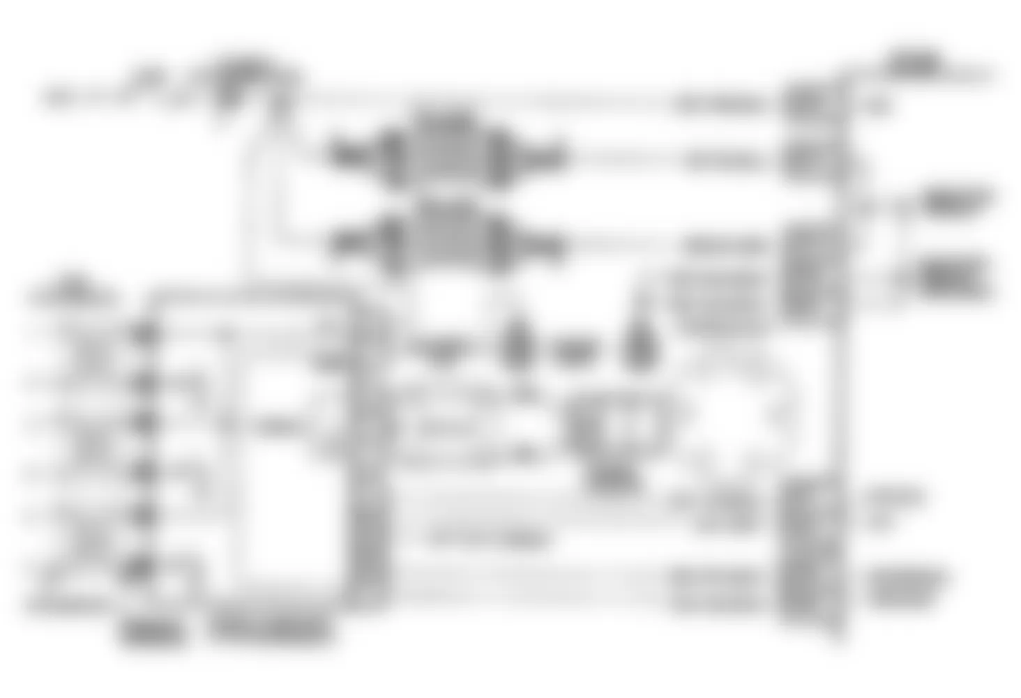
Fig. 70: Buick Regal Custom 1990 - Component Locations - Code 42: EST W/DIS Schematic (J Body)
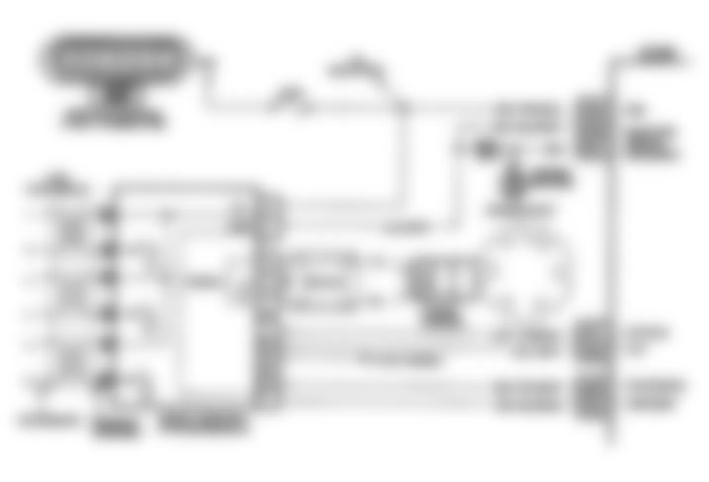
Fig. 71: Buick Regal Custom 1990 - Component Locations - Code 42: EST W/DIS Schematic (L Body)
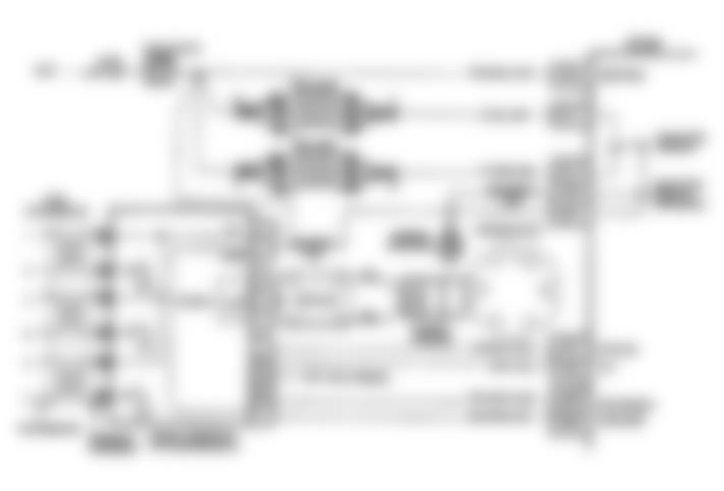
Fig. 72: Buick Regal Custom 1990 - Component Locations - Code 42: EST W/DIS Schematic (W Body)
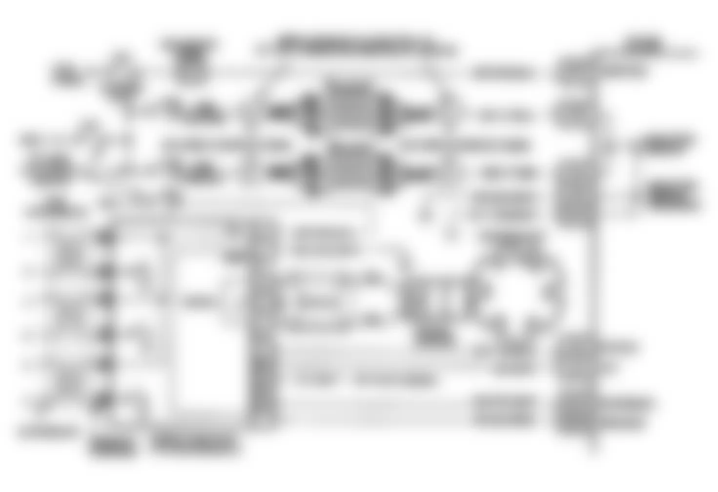
Fig. 73: Buick Regal Custom 1990 - Component Locations - Code 42: EST W/DIS Flow Chart
Buick Regal Custom 1990 - CODE 42: ELECT SPARK TIMING (W/HEI)
When the system is running on the ignition module (no voltage on the by-pass line), the ignition module grounds the EST signal. The ECM expects to see no voltage on the EST line during this condition. If it sees a voltage, it sets Code 42 and will not go into the EST mode. When the RPM for EST operation is reached (400 RPM), by-pass voltage is applied. At this time, the EST should no longer be grounded in the ignition module, so the EST voltage should be varying. If the by-pass line is open or grounded, the ignition module will not switch to EST mode, so the EST voltage will be low and Code 42 will be set. If the EST line is grounded, the ignition module will switch to EST, but because the line is grounded, there will be no EST signal and Code 42 will be set.
NOTE: Test numbers refer to test numbers on diagnostic chart.
- Code 42 means the ECM has seen an open or short to ground in the EST or by-pass circuits. This test confirms Code 42 and that the fault causing the code is present.
- Checks for a normal EST ground path through the ignition module. If EST circuit No. 423 is shorted to ground, it will also read less than 500 ohms. This will be checked later.
- As the test light voltage touches circuit No. 424, the module should switch, causing the ohmmeter to overrange if the meter is in the 1000-2000 ohms position. Selecting the 10,000-20,000 ohms position will indicate a reading greater than 5000 ohms. The important thing is that the module switched.
- The module did not switch and this tests for EST circuit No. 423 for being shorted to ground, by-pass circuit No. 424 open, faulty ignition module connections or module.
- Confirms that Code 42 is a faulty ECM and not an intermittent in circuit No. 423 or 424.
Buick Regal Custom 1990 - Diagnostic Aids
The "Scan" tester does not have the ability to help diagnose a Code 42 problem. A MEM-CAL not fully seated in the ECM can result in a Code 42.
Fig. 74: Buick Regal Custom 1990 - Component Locations - Code 42: ESC W/HEI Schematic (F Body)
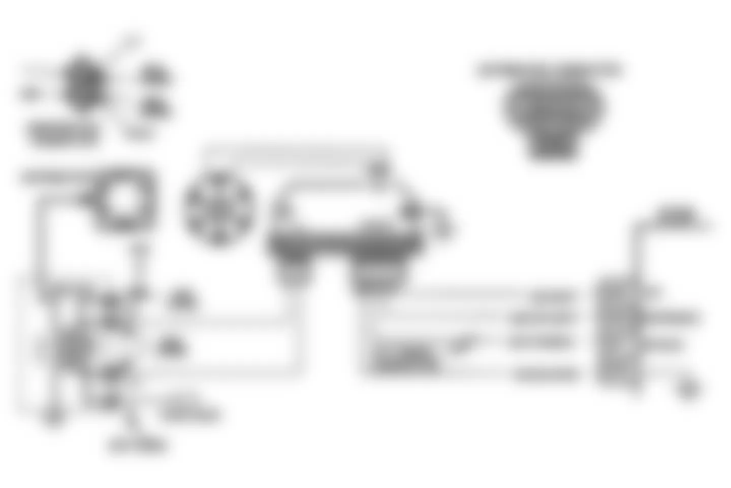
Fig. 75: Buick Regal Custom 1990 - Component Locations - Code 42: ESC W/HEI Flow Chart
Buick Regal Custom 1990 - CODE 43: ELECT SPARK CONTROL
Code 43 indicates the ECM has seen high or low voltage at circuit No. 496 for longer than 5 seconds with the engine running.
NOTE: Test numbers refer to test numbers on diagnostic chart.
- If conditions for test as described above are being met, Code 43 will currently set and the "SES" light will be illuminated.
- The ECM has a 5-volt pull-up resistor, which should be present at the knock sensor terminal.
- This test determines if internal resistance of knock sensor is within an acceptable range.
Buick Regal Custom 1990 - Diagnostic Aids
Check circuit No. 496 for a potential short or open to ground. Also check for proper installation of MEM-CAL. Mechanical engine knock can cause a knock sensor signal. Abnormal engine noise must be corrected before using this chart.
NOTE: Code 43 circuit diagram and flow chart has been updated by Technical Service Bulletin No. 91-6-6, dated 8/24/90.
Fig. 76: Buick Regal Custom 1990 - Component Locations - Code 43: ECS Schematic (A, F, J, L Body)
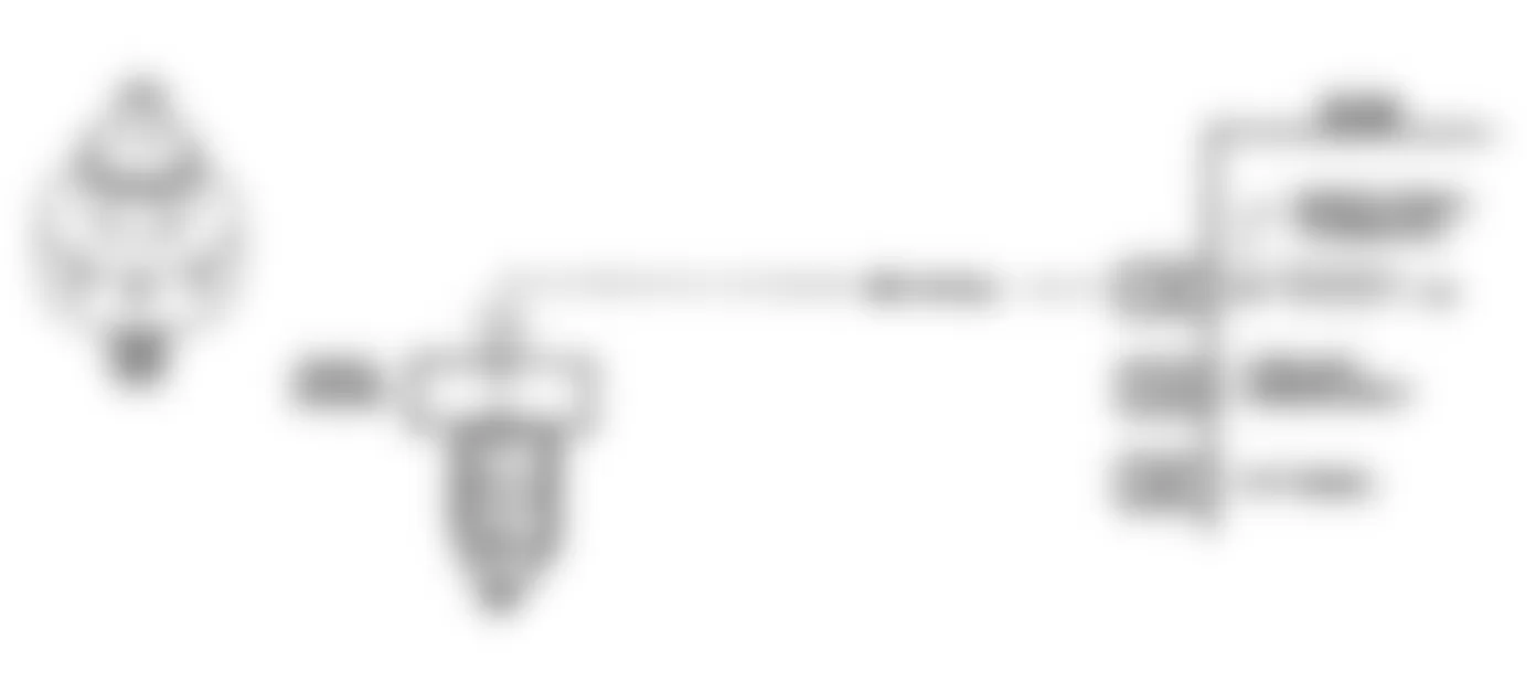
Fig. 77: Buick Regal Custom 1990 - Component Locations - Code 43: ESC Schematic (W Body)
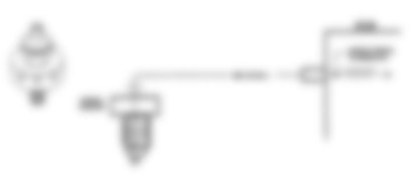
Fig. 78: Buick Regal Custom 1990 - Component Locations - Code 43: ESC Flow Chart
Buick Regal Custom 1990 - CODE 44: LEAN EXHAUST INDICATION
- Code 44 is set when the oxygen sensor signal voltage on circuit No. 412 remains less than .2 volt for at least 50 seconds and the system is operating in closed loop.
Buick Regal Custom 1990 - Diagnostic Aids
Using the "Scan" tester, observe the block learn values under different RPM and airflow conditions. If the conditions for Code 44 exist, the block learn values will be around 150. The following conditions can cause Code 44 to set:
- A faulty Idle Air Control (IAC) circuit.
- O2 sensor pigtail mispositioned and contacting the exhaust manifold.
- Intermittent ground in wire between connector and sensor.
- Lean fuel injectors. Perform injector balance test.
- Water, even in small amounts, near the in-tank fuel pump inlet can be delivered to the injectors and cause a false lean exhaust condition.
- Low fuel pump pressure or volume It may be necessary to monitor fuel pressure while driving the vehicle at various speeds. Check fuel volume from pump (one pint in 30 seconds) as well as pressure. Also check rubber fuel lines for internal collapse.
- Exhaust leak. Outside air may be pulled into the exhaust and past the sensor. Vacuum or crankcase leaks can cause a lean condition.
If the previous areas tests okay, replace oxygen sensor.
Fig. 79: Buick Regal Custom 1990 - Component Locations - Code 44: Lean Exhaust Schematic (A Body)


Fig. 81: Buick Regal Custom 1990 - Component Locations - Code 44: Lean Exhaust Flow Chart
Buick Regal Custom 1990 - CODE 45: RICH EXHAUST INDICATION
- Code 45 is set when the oxygen sensor signal voltage on circuit No. 412 remains greater than .7 volt for at least 30 seconds in closed loop, engine is running for at least one minute and throttle angle is 3-45 percent.
Buick Regal Custom 1990 - Diagnostic Aids
Using the "Scan" tester, observe the block learn values at different RPM and airflow conditions. If the conditions for Code 45 exist, the block learn values will be around 115.
- Check for short to voltage in circuit No. 412.
- Check for leaking injector(s).
- Fuel system will go rich if pressure is too high. The ECM can compensate for some increase; however, if it gets too high, a Code 45 may be set.
- An open in ignition module ground to ECM may result in induced electrical noise. The ECM looks at this noise as reference pulses (RPM). The additional pulses result in a higher than actual engine speed signal. The ECM then delivers too much fuel, causing system to go rich. If this problem occurs, "Scan" tester will show a greater than actual engine speed. This can help in diagnosing this problem.
- Check for fuel-contaminated oil.
- Check vapor canister for fuel saturation. If canister is full of fuel, check canister liquid/vapor control and hoses.
- Check for leaking fuel pressure regulator diaphragm. Remove vacuum line to pressure regulator and check for fuel.
- An intermittent TPS output will cause the system to rich due to a false engine acceleration indication.
- An EGR valve staying open (especially at idle) will cause the O2 sensor to indicate a rich exhaust. This could result in Code 45.
Fig. 82: Buick Regal Custom 1990 - Component Locations - Code 45: Rich Exhaust Schematic (A Body)


Fig. 84: Buick Regal Custom 1990 - Component Locations - Code 45: Rich Exhaust Flow Chart
Buick Regal Custom 1990 - CODE 51: MEM-CAL ERROR
Ensure all pins are fully inserted in the ECM socket. If okay, replace PROM/MEM-CAL. If Code 51 reappears, replace ECM.
Buick Regal Custom 1990 - CODE 52: CALPAK/MEM-CAL ERROR
Ensure all pins are fully inserted in the ECM socket. If okay, replace CALPAK or MEM-CAL. If Code 51 reappears, replace ECM.
Buick Regal Custom 1990 - CODE 53: SYSTEM OVERVOLTAGE
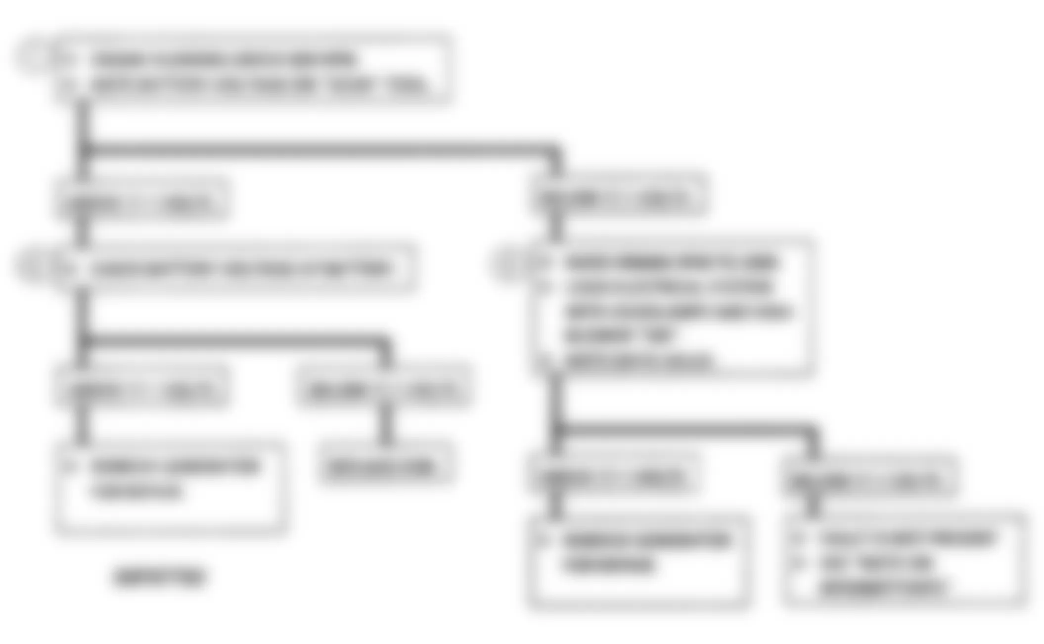
This code indicates a basic charging system problem. Code 53 will set if voltage on ECM battery voltage line increases to greater than 17.1 volts for 2 seconds or more. Check and repair charging system as necessary. During the time this fault is present, ECM outputs will cease. Additional codes may also set in memory.
Fig. 85: Buick Regal Custom 1990 - Component Locations - Code 53: System Overvoltage Schematic
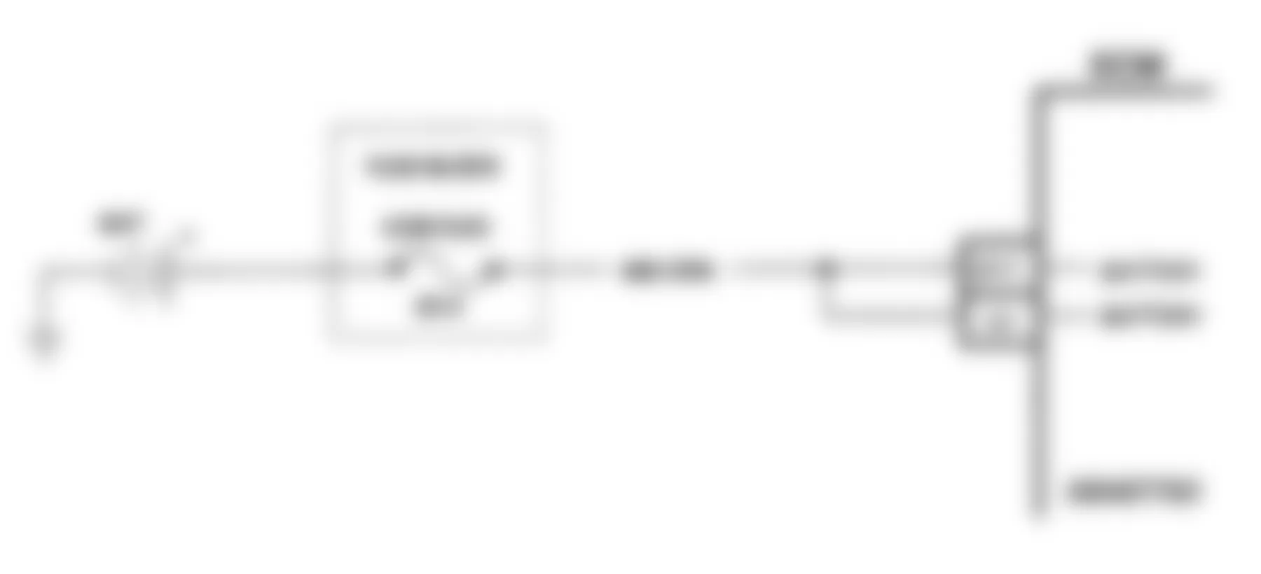
Fig. 86: Buick Regal Custom 1990 - Component Locations - Code 45: System Overvoltage Flow Chart
Buick Regal Custom 1990 - CODE 54: FUEL PUMP VOLT LOW (EXCEPT J & W BODY)
The ECM monitors fuel pump pressure switch circuit voltage for fuel system adjustments. This signal is also used to store a trouble code if the fuel pump relay is defective or fuel pump voltage is lost while the engine is running. There should be about 12 volts on circuit No. 120 for 2 seconds after the ignition is turned on, or any time reference pulses are being received by the ECM.
Code 54 will set if the voltage on circuit No. 120 is less than 2 volts for 1.5 seconds since the last reference pulse is cycled off. However, if the voltage detected is less than 2 volts with the engine running, the light will only remain on while the condition exists. If no fault is found, see the INTERMITTENTS test procedures in the TESTS W/O CODES article.
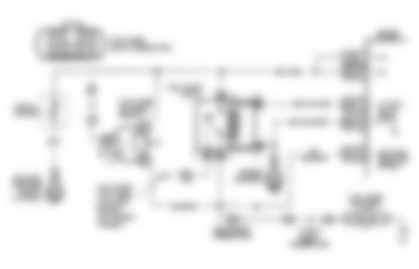
Fig. 90: Buick Regal Custom 1990 - Component Locations - Code 54: Fuel Pump Volt Low Flow Chart
Buick Regal Custom 1990 - CODE 54: FUEL PUMP VOLT LOW (J BODY)
The ECM monitors fuel pump pressure switch circuit No. 120 voltage for fuel system adjustments. This signal is also used to store a trouble code if the fuel pump relay is defective or fuel pump voltage is lost while the engine is running. There should be about 12 volts on circuit No. 120 for 2 seconds after the ignition is turned on, or any time reference pulses are being received by the ECM.
Code 54 will set if the voltage on circuit No. 120 is less than 4 volts for .5 second since the last reference pulse is cycled off, however, if the voltage detected is less than 2 volts with the engine running, the light will only remain on while the condition exists. If no fault is found, see the INTERMITTENTS test procedures in the TESTS W/O CODES article.
Buick Regal Custom 1990 - CODE 54: FUEL PUMP VOLT LOW (W BODY)
Fuel pump circuit No. 120 is monitored by the ECM and is used by ECM for fuel system compensations based on system voltage. This signal is also used to store a trouble code if the fuel pump relay is defective or fuel pump voltage is lost while the engine is running. There should be about 12 volts on circuit No. 120 for 2 seconds after the ignition is turned on, or any time reference pulses are being received by the ECM.
Code 54 will set if the voltage on circuit No. 120 is less than 2 volts for 1.5 seconds since the last reference pulse is cycled off; however, if the voltage detected is less than 2 volts with the engine running, the light will only remain on while the condition exists. Circuits No. 120 and 480 are routed through a Black mini connector to the fuel pump relay. A faulty terminal connection for Orange wire and Gray wire at Black mini connector could cause a Code 54. If no fault is found, see the INTERMITTENTS test procedures in the TESTS W/O CODES article.
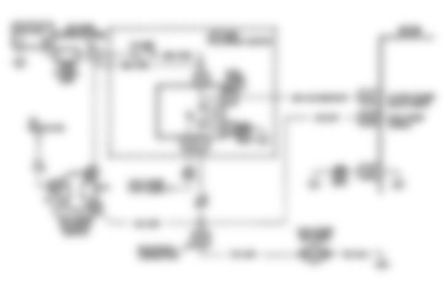
Fig. 93: Buick Regal Custom 1990 - Component Locations - Code 54: Flow Chart (W Body)
Buick Regal Custom 1990 - CODE 55: ECM ERROR (3.1L W BODY NON-TURBO)
Ensure ECM grounds are okay and MEM-CAL is properly installed. If okay, replace ECM. Clear codes and confirm closed loop operation and no SERVICE ENGINE SOON light.
Buick Regal Custom 1990 - CODE 61: DEGRADED OXYGEN SENSOR (3.1L)
If a Code 61 is stored in memory, the ECM has determined the oxygen sensor is contaminated or degraded because the voltage change time (cross counts) is slow or sluggish.
The ECM performs the oxygen sensor response time test when the coolant temperature is more than 185?F (85?C), MAT temperature is greater than 50?F (10?C), system is in closed-loop or in a decel fuel cut-off mode. If Code 61 is stored, the oxygen sensor should be replaced.
Buick Regal Custom 1990 - CODE 62: GEAR SWITCH ERROR (A BODY)
The 2nd gear switch should be open in 2nd and 3rd gear. The ECM uses this signal to disengage TCC when downshifting.
NOTE: Test numbers refer to test numbers on diagnostic chart.
- "Scan" testers display switch status in different manners. - manufacturer's operating manual to determine proper status display. Since both switches should be in the same state during this test, tester should display the same status for both the 2nd and 3rd gear switches.
- Determines whether the switch or signal circuit is open. The circuit can be checked for an open by measuring the voltage at the TCC connector. Reading should be about 12 volts.
- Because the switches should be grounded in this step, disconnecting the TCC connector should cause the "Scan" tester to change status.
- The switch status should change when the vehicle shifts into 2nd gear.
Buick Regal Custom 1990 - Diagnostic Aids
If vehicle is road tested for a TCC related problem, ensure the switch status does not change while in 3rd gear because the TCC will disengage. If switches change status, carefully check wire harness/routing and connectors.
Buick Regal Custom 1990 - CODE 62: GEAR SWITCH ERROR (3.1L J BODY)
The 2nd gear switch should be open in 2nd and 3rd gear. The ECM uses this signal to disengage TCC when downshifting.
NOTE: Test numbers refer to test numbers on diagnostic chart.
- "Scan" testers display switch status in different manners. - manufacturer's operating manual to determine proper status display.
- Determines whether the switch or signal circuit is open. The circuit can be checked for an open by measuring the voltage at the TCC connector. Reading should be about 12 volts.
- Because the switches should be grounded in this step, disconnecting the TCC connector should cause the "Scan" tester to change status.
- The switch status should change when the vehicle shifts into 2nd gear.
Buick Regal Custom 1990 - Diagnostic Aids
If vehicle is road tested for a TCC related problem, ensure the switch status does not change while in 3rd gear because the TCC will disengage. If switches change status, carefully check wire harness/routing and connectors.
Buick Regal Custom 1990 - CODE 62: GEAR SWITCH ERROR (3.1L L BODY)
The 2nd gear switch should be open in 2nd and 3rd gear. The ECM uses this signal to disengage TCC when downshifting.
NOTE: Test numbers refer to test numbers on diagnostic chart.
- "Scan" testers display switch status in different manners. - manufacturer's operating manual to determine proper status display.
- Determines whether the switch or signal circuit is open. The circuit can be checked for an open by measuring the voltage at the TCC connector. Reading should be about 12 volts.
- Because the switches should be grounded in this step, disconnecting the TCC connector should cause the "Scan" tester to change status.
- The switch status should change when the vehicle shifts into 2nd gear.
Buick Regal Custom 1990 - Diagnostic Aids
If vehicle is road tested for a TCC related problem, ensure the switch status does not change while in 3rd gear because the TCC will disengage. If switches change status, carefully check wire harness/routing and connectors.
Buick Regal Custom 1990 - CODE 66: A/C PRESSURE SENSOR (3.1L J BODY)
The A/C pressure sensor responds to changes in A/C refrigerant system high side pressure. The ECM uses A/C compressor load input to determine engine idle speed. Sensor uses a 5-volt reference signal from the ECM and returns an input signal to the ECM on a separate line. Low pressure (zero psi) will return a signal of about .1 volt. High pressure will return a signal of about 4.9 volts.
NOTE: Test numbers refer to test numbers on diagnostic chart.
- Checks voltage signal from A/C pressure sensor to ECM.
- Checks to see if high signal is from a shorted sensor or a short to voltage in the circuit. Normally, disconnecting the sensor would make a normal circuit go to nearly zero volts.
- Checks to see if low voltage signal is from the sensor or circuit. Jumpering the sensor signal circuit to 5 volts checks the circuit, connections and ECM.
- Checks to see if the low voltage signal was due to an open in the sensor circuit since the prior step eliminated the pressure sensor.
Buick Regal Custom 1990 - Diagnostic Aids
Code 66 sets when signal voltage falls outside the normal sensor range and is not due to a A/C system problem. If problem is intermittent, check for opens or shorts in harness or poor connections. If okay, replace pressure sensor. If code resets, replace ECM.
Buick Regal Custom 1990 - SUMMARY
If no hard fault codes are present, driveability symptoms exist or intermittent codes exist, go to TESTS W/O CODES article for diagnosis by symptom (i.e. ROUGH IDLE, NO START, etc.), or intermittent diagnostic procedures.