Buick Skylark 1991 - G - TESTS W/CODES - 2.3L PFI 1991 ENGINE PERFORMANCE General Motors 2.3L PFI - Self-Diagnostics - ECM/PCM
Buick Skylark 1991 - INTRODUCTION
NOTE: This article Covers Vehicles Equipped With Port Fuel Injected 2.3L Engine Only.
Most engine control problems are the result of mechanical breakdowns, poor electrical connections or damaged vacuum hoses. Before considering the computer system as a possible cause of problems, perform checks and inspections covered in BASIC TESTING article in this section. Failure to do so may result in lost diagnostic time.
If no faults were found while performing BASIC TESTING article proceed with DIAGNOSTIC PROCEDURE. If no fault codes or only a non-running Code 12 is present and driveability problems exist, proceed to TESTS W/O CODES article for diagnosis by symptom (i.e. ROUGH IDLE, NO START, etc.). If only intermittent codes are present, see INTERMITTENTS in TESTS W/O CODES article in this section.
Buick Skylark 1991 - SELF-DIAGNOSTIC SYSTEM
All vehicle are equipped with either an Electronic Control Module (ECM) or Powertrain Control Module (PCM). Unless specifically stated, references to ECM also apply to PCM equipped vehicles. Control module is equipped with a self-diagnostic system, which detects system failures or abnormalities. When a malfunction occurs, control module will illuminate the SERVICE ENGINE SOON light located on instrument panel. When malfunction is detected and light is turned on, a corresponding trouble code will be stored in control module memory. To retrieve stored codes, see RETRIEVING CODES (NON-SCAN) in this article. Malfunctions are recorded as HARD FAILURES or as INTERMITTENT FAILURES.
Buick Skylark 1991 - HARD FAILURES
Hard failures cause SERVICE ENGINE SOON light to illuminate and remain on until the malfunction is repaired. If light comes on and remains on (light may flash) during vehicle operation, cause of malfunction must be determined using diagnostic (code) charts. If a sensor fails, control module will use a substitute value in its calculations to continue engine operation. In this condition, vehicle is functional, but most likely degraded driveability will be encountered.
Buick Skylark 1991 - INTERMITTENT FAILURES
Intermittent failures cause SERVICE ENGINE SOON light to flicker or illuminate and go out about 10 seconds after the intermittent fault goes away. The corresponding trouble code, however, will be retained in control module memory. If related fault does not reoccur within 50 engine restarts, related trouble code will be erased from control module memory. Intermittent failures may be caused by sensor, connector or wiring related problems. See INTERMITTENTS in TESTS W/O CODES article in this section.
Buick Skylark 1991 - DIAGNOSTIC PROCEDURE
Diagnosis of the computerized engine control system should be performed in the following order:
- Make sure all engine systems not related to the computer system are operating properly. DO NOT proceed with testing unless all other problems have been repaired. DIAGNOSTIC CIRCUIT CHECK must be performed prior to utilizing trouble code charts. See BASIC TESTING article in this section.
- If trouble codes were displayed (other than Code 12), decide whether codes are hard or intermittent trouble codes. Hard codes will cause the SERVICE ENGINE SOON light to illuminate continuously while engine is running. See HARD OR INTERMITTENT TROUBLE CODE DETERMINATION in this article. For diagnosing hard codes, proceed to appropriate trouble code chart in this article. For diagnosing intermittent codes, proceed to INTERMITTENTS in TESTS W/O CODES article in this section. Exceptions are Code 13, 15, 24, 44 and 45 charts, which may be used to help diagnose intermittent codes.
- If no trouble codes were displayed and a driveability problem exists, refer to SYMPTOMS in TESTS W/O CODES article in this section. The comments there will send you to the proper system or component to check in the SYSTEM/COMPONENT TESTS article in this section.
- After any repairs are made, clear any trouble codes and perform FIELD SERVICE MODE check in BASIC TESTING article in this section.
Buick Skylark 1991 - RETRIEVING CODES (NON-SCAN)
NOTE: For information on retrieving codes using a "Scan" tester, refer to owners manual supplied with "Scan" tester. On Reatta, Riviera, Toronado and Trofeo, codes can also be retrieved through the Electronic Climate Control Panel (ECCP). For additional information on ECCP function, see appropriate BCM TROUBLE CODE CHARTS in this article.
- Turn ignition on. DO NOT start engine. SERVICE ENGINE SOON light should glow. Locate Assembly Line Data Link (ALDL) connector attached to control module wiring harness. Most ALDL connectors are located under dash on driver's side of vehicle. For exact location of ALDL, see COMPONENT LOCATIONS illustration in I - SYSTEM/COMPONENT LOCATIONS article in this section. Turn ignition on with engine not running. Insert jumper wire from terminal "B" (diagnostic test terminal) to terminal "A" (ground) of ALDL connector. See Fig. 1 .
NOTE: Inserting jumper wire into test and ground terminals of ALDL connector with engine running will cause fuel injected vehicles to enter field service mode. Flashes of the SERVICE ENGINE SOON light will not indicate codes if this is done. See FIELD SERVICE MODE in BASIC TESTING article in this section. 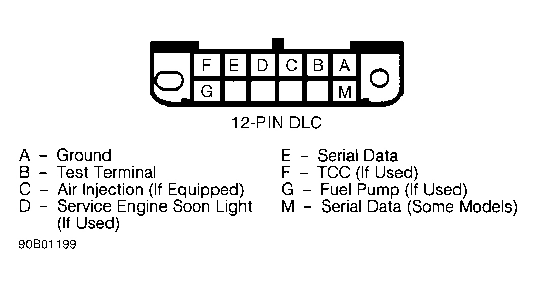
Fig. 1: Buick Skylark 1991 - Component Locations - ALDL Connector Terminal Identification - SERVICE ENGINE SOON light should begin to flash codes. Each code will be repeated 3 times. If codes are not flashed or SERVICE ENGINE SOON light does not illuminate, perform DIAGNOSTIC CIRCUIT CHECK in BASIC TESTING article in this section. To exit diagnostic mode, turn ignition off and remove jumper wire from ALDL connector.
Buick Skylark 1991 - READING TROUBLE CODES
The control module stores component failure information under a related trouble code which can be recalled for diagnosis and repair. Trouble codes may be read by counting flashes of the SERVICE ENGINE SOON light, or by reading the output of a diagnostic "Scan" tester connected to the ALDL connector. The tester is faster to use, more accurate, and capable of reading information which otherwise would necessitate testing individual control module and sensor/solenoid connector terminals with a digital voltmeter. See SCAN TESTER USAGE and tables under SCAN DATA in this article.
NOTE: When using a "Scan" tester, there is a time delay between serial data updates. For instantaneous response, a digital voltmeter must be used.
If "Scan" tester is not available, it is possible to read flashes of the SERVICE ENGINE SOON light by grounding the diagnostic test terminal "B" of the ALDL with ignition on and engine off. For example, FLASH, FLASH, pause, FLASH, longer pause, identifies Code 21. The first series of flashes are the first digit of trouble code. The second series of flashes are the second digit of trouble code. Trouble codes are displayed starting with the lowest numbered code. Each code is displayed 3 times. Codes will continue to repeat as long as ALDL test terminal is grounded.
NOTE: Trouble codes will be recorded at various operating times. Some codes require operation of that sensor or switch for 5 seconds; others may require operation for 5 minutes or longer at normal operating temperature, road speed and load. Therefore, some codes may not set in a service bay operational mode and may require road testing vehicle in order to duplicate condition under which code will set.
Buick Skylark 1991 - TROUBLE CODE DEFINITION
Buick Skylark 1991 ECM/PCM TROUBLE CODE DEFINITION
Code No. Circuit Affected 12 (1) No RPM Reference Pulse 13 Open Oxygen Sensor Circuit 14 CTS Signal Voltage Low 15 CTS Signal Voltage High 16 System Voltage High 17 RPM Signal Problem (3.8L C Body) 21 TPS Signal Voltage High 22 TPS Signal Voltage Low 23 MAT Sensor Signal Voltage High 24 Vehicle Speed Sensor Circuit 25 MAT Sensor Signal Voltage Low 26 Quad-Driver Error 32 EGR System Error 33 MAP Sensor Signal Voltage High 34 MAP Sensor Signal Voltage Low 35 IAC Idle Speed Error 36 (2) Trans. Shift Circuit 41 1X Signal Loss 42 EST Circuit Open Or Grounded 43 ESC Error 44 Lean Exhaust Indication 45 Rich Exhaust Indication 46 Anti-Theft System Fault " Power Steering Pressure Switch 51 Faulty PROM, MEM-CAL or ECM/PCM 52 Faulty/Missing CALPAC or MEM-CAL 53 System Overvoltage " Anti-Theft System Fault 54 Fuel Pump Voltage Low 55 ECM/PCM Error 61 (2) Cruise Vent Solenoid 62 (2) Cruise Vacuum Solenoid 65 Fuel Injector Current Low " (2) Cruise servo position 66 A/C Pressure Sensor Voltage Out Of Specification 67 (2) Cruise Engage Switches 68 (2) Cruise System Problem
(1) Display of a Code 12 is normal when no reference pulses are received by control module (engine not running).
(2) PCM equipped models.
NOTE: Trouble code charts should only be used if SERVICE ENGINE SOON light is illuminated (indicating a current problem exists). Exceptions are Code 13, 15, 24, 44 and 45 charts, which may be used to help diagnose intermittent codes. Anytime control module-related Codes 51, 52 or 55 are displayed with another code, start with 50-series code first, then proceed to low profile numbered codes.
Buick Skylark 1991 - HARD OR INTERMITTENT TROUBLE CODE DETERMINATION
During any diagnostic procedure, it must be determined if codes are hard failure codes or intermittent failure codes. Diagnostic charts will not usually help analyze intermittent codes. To determine hard codes and intermittent codes, proceed as follows:
- MANUALLY enter diagnostic mode. Read and record all stored trouble codes. Exit diagnostic mode and clear trouble codes. See CLEARING TROUBLE CODES.
- Apply parking brake and place transmission in Neutral or Park. Block drive wheels and start engine. SERVICE ENGINE SOON light should go out. Run warm engine at specified curb idle for 2 minutes and note SERVICE ENGINE SOON light.
- If SERVICE ENGINE SOON light comes on, MANUALLY enter diagnostic mode. Read and record trouble codes. This will reveal hard failure codes. Codes 13, 15, 24, 44, 45 and 55 may require a road test to reset hard failure after trouble codes were cleared.
- If SERVICE ENGINE SOON light does not come on, all stored trouble codes were intermittent failures. Exceptions are noted under DIAGNOSTIC PROCEDURE.
Buick Skylark 1991 - CLEARING TROUBLE CODES
Turn ignition switch to ON position and ground diagnostic test terminal "B" at ALDL connector. Turn ignition switch to OFF position and remove control module fuse from fuse block for 10 seconds. Replace fuse. Remove diagnostic terminal ground lead. If fuse cannot be located, pigtail at battery can be disconnected. When power to ECM is removed, degraded driveability may be exhibited until control module "relearns" optimum operational parameters.
Buick Skylark 1991 - ECM/PCM LOCATION
On most vehicles the engine control module is located behind the right or left side of the dash, or behind the right or left kick panel. On the Grand Prix and Lumina, the control module is located on the right side of the engine compartment. On Corvette, the control module is located in the left rear corner of the engine compartment, next to the battery. For illustration of engine control module locations see COMPONENT LOCATIONS in I - SYSTEM/COMPONENT LOCATIONS article in this section.
Buick Skylark 1991 - DIAGNOSTIC MATERIALS Diagnostic Aids
Diagnostic aids (located in many trouble code charts) are additional tips used to help diagnose trouble codes when inspected circuit checks out okay. Diagnostic aids may help lead to a definitive solution to that trouble code problem.
Buick Skylark 1991 - Field Service Mode Check
If ALDL test terminal "B" is grounded with engine running, SERVICE ENGINE SOON light will indicate operational mode of engine. This test confirms proper operation of fuel system and verifies closed loop operation. Clear codes and perform this test after any repair is completed. Field service mode check can be found by proceeding to FIELD SERVICE MODE CHECK in BASIC TESTING article in this section.
Buick Skylark 1991 - SPECIAL TOOLS (DIAGNOSTIC)
NOTE: Special "Scan" testers plugged into the ALDL may be used to read trouble codes and check voltages in the system on the serial data line (terminal "E", or terminal "M" on P-4 systems). These testers can save a great deal of time. For additional information, see SCAN TESTER USAGE and tables under SCAN DATA in this article.
The computerized engine control system is most easily diagnosed using a "Scan" tester; however, other tools may aid in diagnosing problems if a "Scan" tester is unavailable. These tools are a tachometer, test light, ohmmeter, digital voltmeter with 10-megohm input impedance (minimum), vacuum pump, vacuum gauge, fuel injector test lights and 6 jumper wires 6" long (one wire with female connectors at both ends, one wire with male connector at both ends and 4 wires with male and female connectors at opposite ends). A test light, rather than a voltmeter, must be used when indicated by a diagnostic chart.
Buick Skylark 1991 - SCAN TESTER USAGE
NOTE: Prior to connection of "Scan" tester to vehicle, diagnostic system should be checked to determine if system is operating properly and if information received by "Scan" tester will be accurate. This is done by performing DIAGNOSTIC CIRCUIT CHECK located in BASIC TESTING article in this section. If vehicle does not pass diagnostic circuit check, information received by "Scan" tester may be invalid.
The "Scan" tester is a specialized tester which, when plugged into ALDL, can be used to diagnose on-board computer control systems by providing instant access to circuit voltage information without need to crawl under dash or hood to backprobe sensors and connectors. "Scan" testers cut down diagnostic time dramatically by furnishing input data (voltage signals) which can be compared to specification parameters. See tables under SCAN DATA in this article. They may also furnish information on output device (solenoids and motors) status. However, status parameters are only an indication that output signals have been sent to devices by the control module. It does not indicate if devices have responded properly to that signal. This will need to be verified at output device using a voltmeter or test light.
NOTE: Code 12 should always exist when ALDL is grounded with key on and engine not running, but may not be indicated by all makes of "Scan" testers.
If trouble codes are not present, this is not an indication that there is not a problem. Driveability related problems with codes displayed occur about 20 percent of the time, while driveability problems without codes occur about 80 percent of the time. Sensors that are out of specification WILL NOT set a trouble code but WILL cause driveability problems. Using a "Scan" tester is the easiest method of checking sensor specifications and other data parameters. Tester is also useful in finding intermittent wiring problems by wiggling wiring harnesses and connections (key on, engine off) while observing data parameters. See tables under SCAN DATA in this article.
NOTE: Information obtained by "Scan" tester is only as accurate as the tester itself. If erroneous voltage signals are suspected, it will be necessary to verify tester information using a digital voltmeter and wiring schematic. If non-existent codes are displayed, turn ignition off, remove tester, turn ignition on and ground ALDL test terminal "B". If same codes are not flashed by SERVICE ENGINE SOON light that were indicated by "Scan" tester, tester cannot be used on vehicle and information obtained by it will not be guaranteed accurate.
Buick Skylark 1991 - SCAN DATA
NOTE: Information contained in the following tables is typical of readings taken on vehicle with engine idling, upper radiator hose hot, closed throttle, transmission in Park or Neutral, closed loop status achieved and all accessories off (except as noted in tables). Data parameters are updated every 1 1/4 seconds. On systems using P-4 computers, parameter updates are more often. Not all devices and systems are used on all models and the following lists represent only the most commonly used parameters. For additional information, refer to owners manual furnished with tester.
Buick Skylark 1991 PORT FUEL INJECTION
Tester Position Units Measured Nominal Data Value A/C Clutch On/Off Off (On With A/C) A/C Request Yes/No No/Yes (With Request) AIR Divert Sol. On/Off On (Air To Switching Sol.); Off (Air To Atmosphere) AIR Switching Sol. On/Off On (To Exhaust Manifold); OFF (To Catalytic Converter) BARO Volts 3-4.5 Battery Voltage Volts 13.5-14.5 Block Learn Counts 118-138 (128 Normal) Canister Purge Sol. On/Off On/Engine Cold (Idle Some) Clear Flood On/Off See Tester Manual Coolant Fan On/Off Off below 216?F (102?C) Coolant Temp. ?C 85-105? (Norm. Temperature) Crank RPM RPM 100-900 Cross Counts Counts 0-255EGR Solenoid On/Off On When Energized EGR Duty Cycle 0-100% 0/Closed-100/fully Open Fan Relay On/Off On When Energized Fan Request On/Off On With Request Fuel Back-Up Yes/No Yes When Engaged IAC Counts 0-50 Ignition/Crank On/Off On With Ignition/Crank Injector Pulse Width Mil./Sec .8-3.0 INT (Integrator) Counts 110-145 (128 Normal) Knock Retard (ESC) Counts 0-255 Knock Signal Yes/No Yes When Knock Exists MAT ?C 10-90? MAP Volts 1 (Idle) to 4.5 (WOT) Open/Closed Loop Status Ol/Cl Closed/Open During Extended Idle O2 Sensor Millivolts 100 (Lean) To 999 (Rich) P/N Switch P/N/RDL Park/Neutral P/S Switch Norm/Hi Normal PROM I.D. PROM # Original Factory Number RPM RPM Spec. +/-25 RPM Drive (Auto.) " " Spec. +/-50 RPM Neut. (Man.) Spark Advance No. Deg. Varies TCC On/Off Off (On With Command) TPS Volts 1.25 (Idle) to 5.0 (WOT) Throttle Angle 0-100% 0 (Idle) To 100 (WOT) Trouble Codes Code # No Codes Upshift Light (M/T) On/Off Off VSS or MPH MPH 0-Actual Water Injection On/Off On When Injecting 1st Gear Switch On/Off On/1st Gear Only 3rd Gear Switch On/Off On/3rd & 4th Gear 4th Gear Switch On/Off On/4th Gear
Buick Skylark 1991 - TEST PROCEDURE SUMMARY
If no hard fault codes are present, driveability symptoms exist or intermittent codes exist, proceed to TESTS W/O CODES article in this section for diagnosis by symptom (i.e. ROUGH IDLE, NO START, etc.), or intermittent diagnostic procedures.
Buick Skylark 1991 - DIAGNOSTIC FLOW CHARTS FOR CODES: 13 TO 66
NOTE: Mini-schematics are supplied courtesy of General Motors Corp.
Buick Skylark 1991 - CODE 13, OPEN OXYGEN SENSOR CIRCUIT
NOTE: Test numbers refer to test numbers on diagnostic chart.
- This tests if problem still exists. Vehicle cannot enter closed loop mode if oxygen sensor circuit is open. Code 13 indicates an open in the O2 sensor circuit. Code will set if:
- Engine is at normal operating temperature.
- Neither Code 21 nor Code 22 are stored.
- O2 sensor voltage is constant within a specified range (.34-.55 volt).
- Throttle angle is greater than idle.
- A precalibrated amount of time has elapsed since start-up.
- All conditions have existed for a precalibrated amount of time.
- Determines if O2 sensor, wiring or control module is at fault. If wiring is good, grounding oxygen sensor wire will cause .45 volt reference supplied by the control module to pull low.
- This tests O2 sensor circuit wiring. Use only a high impedance (10-megohm minimum) digital voltmeter.
Buick Skylark 1991 - Diagnostic Aids
Control module will not go into closed loop if Code 13 is set. Code 13 may set if vehicle runs out of fuel or stalls while vehicle is in motion. If oxygen sensor ground becomes loose, a false oxygen sensor reading will occur. This can result in a Code 13 being set.
Fig. 2: Buick Skylark 1991 - Component Locations - Code 13, Schematic, Open Oxygen Sensor Circuit
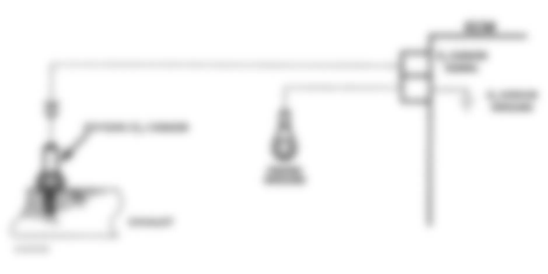
Fig. 3: Buick Skylark 1991 - Component Locations - Code 13, Flow Chart, Open Oxygen Sensor Circuit

Buick Skylark 1991 CODE 13 ECM TERMINAL & CIRCUIT WIRING IDENTIFICATION
Application ECM Terminal Wire Color L Body O2 Signal GE14 Black O2 Ground GE15 Tan N Body O2 Signal GE14 Purple O2 Ground GE15 Tan W Body O2 Signal A16 Purple O2 Ground A22 Tan
Buick Skylark 1991 - CODE 14, COOLANT TEMPERATURE SENSOR SIGNAL VOLTAGE LOW
NOTE: This chart assumes engine cooling system is functioning properly (not overheating). Test numbers refer to test numbers on diagnostic chart.
- Code 14 indicates the control module has seen low coolant sensor voltage signal (high temperature) at control module terminal for a precalibrated period of time. This checks if conditions for Code 14 still exist.
- This tests for grounded sensor signal line between control module and coolant sensor.
Buick Skylark 1991 - Diagnostic Aids
After the engine is started, temperature should rise steadily to about 190?F (88?C), then stabilize when thermostat opens. At normal operating temperature, signal voltage at control module terminal should be 1.5-2.0 volts. Check sensor for shifted calibration by using sensor TEMPERATURE-TO-RESISTANCE VALUES table. When Code 14 is set, control module will turn on electric cooling fan(s), if equipped.

NOTE: For shared sensor ground tie-offs, see appropriate diagram in WIRING DIAGRAMS.

Buick Skylark 1991 CODE 14 ECM TERMINAL & CIRCUIT WIRING IDENTIFICATION
Application ECM Terminal Wire Color W Body CTS Signal C16 Yellow CTS Ground C10 Black N Body CTS Signal GE16 Yellow CTS Ground BB6 Black
Buick Skylark 1991 TEMPERATURE-TO-RESISTANCE VALUES (1)
Temperature ?F (?C) Ohms 210 (100) 185 160 (70) 450 100 (38) 1800 70 (20) 3400 20 (-7) 13,500 0 (-18) 25,000 -40 (-40) 100,700
(1) Measure resistance across sensor terminals.
Buick Skylark 1991 - CODE 15, COOLANT TEMPERATURE SENSOR SIGNAL VOLTAGE HIGH
NOTE: Test numbers refer to test numbers on diagnostic chart.
- Code 15 indicates control module has seen high resistance in coolant sensor circuit. This could be due to high resistance (cold temperature) or high voltage at coolant sensor terminal at control module for a precalibrated period of time. This checks if conditions for Code 15 still exist.
- This test simulates conditions for a Code 14. If control module recognizes the low voltage signal, "Scan" tester will display greater than 130?C. This indicates the control module and wiring are not at fault.
- This test determines if coolant sensor ground or signal circuit is open.
Buick Skylark 1991 - Diagnostic Aids
After the engine is started, temperature should rise steadily to about 190?F (88?C), then stabilize when thermostat opens. At normal operating temperature, voltage at control module sensor signal line should be 1.5-2.0 volts. Check sensor for shifted calibration by using sensor temperature-to-resistance table. When Code 14 is set, control module will turn on electric cooling fan(s), if equipped.

NOTE: For shared sensor ground tie-offs, see appropriate diagram in WIRING DIAGRAMS.

Buick Skylark 1991 CODE 15 ECM TERMINAL & CIRCUIT WIRING IDENTIFICATION
Application ECM Terminal Wire Color W Body CTS Signal C16 Yellow CTS Ground C10 Black N Body CTS Signal GE16 Yellow CTS Ground BB6 Black
Buick Skylark 1991 TEMPERATURE-TO-RESISTANCE VALUES (1)
Temperature ?F (?C) Ohms 210 (100) 185 160 (70) 450 100 (38) 1800 70 (20) 3400 20 (-7) 13,500 0 (-18) 25,000 -40 (-40) 100,700
(1) Measure resistance across sensor terminals.
Buick Skylark 1991 - CODE 21, THROTTLE POSITION SENSOR SIGNAL VOLTAGE HIGH
NOTE: Test numbers refer to test numbers on diagnostic chart.
- This test checks if code is the result of a hard failure or an intermittent condition.
- This test simulates conditions for a Code 22. If control module recognizes the change of state, the control module and wiring are okay.
- This step isolates a faulty sensor, control module or open sensor ground circuit. If sensor ground is shared by another sensor, there may be an accompanying code related to that sensor.
Buick Skylark 1991 - Diagnostic Aids
A "Scan" tester displays throttle position in volts. Closed throttle voltage should be low. Voltage should increase gradually to about 4.5 volts at a steady rate, as throttle angle is increased. If code is intermittent, see INTERMITTENTS in TESTS W/O CODES article in this section.

NOTE: For shared sensor reference and shared sensor ground tie-offs, see appropriate diagram in WIRING DIAGRAMS.

Buick Skylark 1991 CODE 21 ECM TERMINAL & CIRCUIT WIRING IDENTIFICATION
Application ECM Terminal Wire Color L & N Bodies TPS Signal GF13 Dark Blue TPS Ground BB6 Black TPS Reference BA5 Gray W Body TPS Signal C15 Dark Blue TPS Ground C10 Black TPS Reference C12 Gray
Buick Skylark 1991 - CODE 22, THROTTLE POSITION SENSOR SIGNAL VOLTAGE LOW
NOTE: Test numbers refer to test numbers on diagnostic chart.
- This test checks if code is the result of a hard failure or an intermittent condition.
- This test simulates conditions for a Code 21. If control module recognizes the change of state, the control module and wiring are okay.
- This simulates a high signal voltage to check for an open in the TPS signal line to control module. "Scan" tester should recognize this signal and display high TPS voltage.
Buick Skylark 1991 - Diagnostic Aids
A "Scan" tester displays throttle position in volts. Closed throttle voltage should be low. Voltage should increase gradually to about 4.5 volts at a steady rate, as throttle angle is increased. If code is intermittent, see INTERMITTENTS in TESTS W/O CODES article in this section.

NOTE: For shared sensor reference and shared sensor ground tie-offs, see appropriate diagram in WIRING DIAGRAMS.

Buick Skylark 1991 CODE 22 ECM TERMINAL & CIRCUIT WIRING IDENTIFICATION
Application ECM Terminal Wire Color L & N Bodies TPS Signal GF13 Dark Blue TPS Ground BB6 Black TPS Reference BA5 Gray W Body TPS Signal C15 Dark Blue TPS Ground C10 Black TPS Reference C12 Gray
Buick Skylark 1991 - CODE 23, MAT SENSOR SIGNAL VOLTAGE HIGH
NOTE: Test numbers refer to test numbers on diagnostic chart.
- This checks if code is the result of a hard failure or an intermittent condition. Code 23 will set if engine has been running for a precalibrated period of time, has reached operating temperature and signal voltage indicates a MAT temperature less than -22?F (-30?C).
- This simulates conditions for a Code 25. If the "Scan" tester displays a high temperature, the control module and wiring are not at fault.
- This checks for continuity of sensor signal and ground circuits. If ground circuit is shared by other sensors and ground circuit is open, accompanying codes related to those sensors may be present.
Buick Skylark 1991 - Diagnostic Aids
If the engine is allowed to cool overnight, the coolant and MAT sensors should read close to each other, when measured with a "Scan" tester. A Code 23 will result if signal and ground circuits become open. Check sensor for shifted calibration by using sensor TEMPERATURE-TO-RESISTANCE VALUES table.

NOTE: For shared sensor ground tie-offs, see appropriate diagram in WIRING DIAGRAMS.

Buick Skylark 1991 CODE 23 ECM TERMINAL & CIRCUIT WIRING IDENTIFICATION
Application ECM Terminal Wire Color L Body MAT Signal GF16 Black/Pink MAT Ground BB5 Black W Body MAT Signal C4 Tan MAT Ground C5 lack
Buick Skylark 1991 TEMPERATURE-TO-RESISTANCE VALUES (1)
Temperature ?F (?C) Ohms 210 (100) 185 160 (70) 450 100 (38) 1800 70 (20) 3400 20 (-7) 13,500 0 (-18) 25,000 -40 (-40) 100,700
(1) Measure resistance across sensor terminals.
Buick Skylark 1991 - CODE 24, L, N & W BODIES, VEHICLE SPEED SENSOR (VSS)
The speed sensor, which is a Permanent Magnet (PM) generator, provides the control module with vehicle speed information. The PM generator, mounted in the transmission, produces a pulsing voltage signal whenever the vehicle speed is more than 3 MPH. The voltage level and pulses increase with vehicle speed. The control module converts the pulsing voltage to MPH, which is used by the control module in calculations to determine vehicle adjustments.
NOTE: Test numbers refer to test numbers on diagnostic chart.
- A Code 24 will set when MPH reads zero, transmission is not in Park or Neutral, engine speed indicates vehicle is in a cruise mode (1200-4400) RPM, TPS indicates closed throttle and high manifold vacuum is sensed by the MAP sensor. All of these conditions must be met for 2-5 seconds. The PM generator only produces a voltage signal if drive wheels are turning greater than 3 MPH.
- Before replacing the control module, PROM/MEM-CAL should be checked for correct application.
Buick Skylark 1991 - Diagnostic Aids
A faulty or misadjusted park/neutral switch may set a false Code 24. Use "Scan" tester and check for proper signal in Drive, while wiggling shifter. Code 24 may set if vehicle is power braked (brakes applied and throttle depressed) for more than 10 seconds.
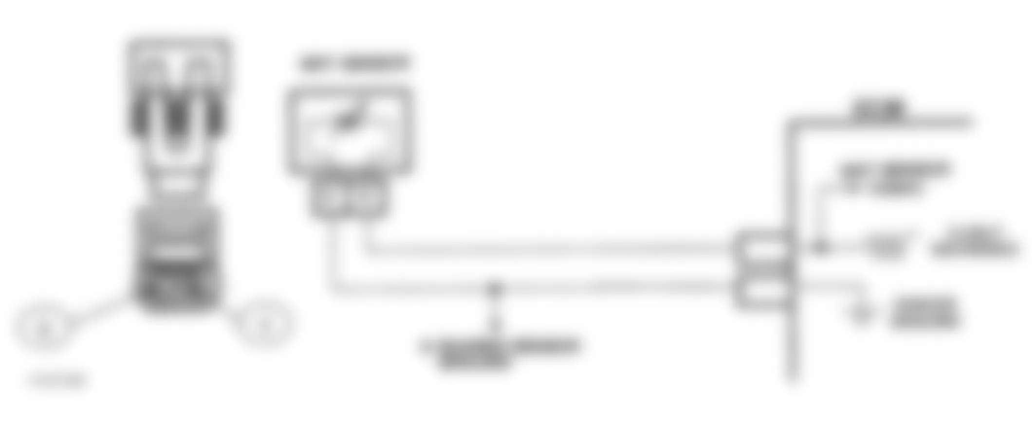
Fig. 14: Buick Skylark 1991 - Component Locations - Code 24, Schematic, W Body, Speed Sensor (VSS)


NOTE: Disregard Code 24 that sets while wheel are not turning.
Fig. 16: Buick Skylark 1991 - Component Locations - Code 24, Flow Chart, (All) Speed Sensor (VSS)

Buick Skylark 1991 - CODE 25, MAT SENSOR SIGNAL VOLTAGE LOW
NOTE: Test numbers refer to test numbers on diagnostic chart.
- This checks if the code is a hard failure or an intermittent condition. Code 25 will set if a MAT temperature greater than 266?F (130?C) is sensed for more than a precalibrated period.
- This simulates condition for Code 23. if control module recognizes the open circuit and "Scan" tester displays a temperature of less than -30? C, control module and wiring are okay.
Buick Skylark 1991 - Diagnostic Aids
If the engine is allowed to cool overnight, the coolant temperature sensor and MAT sensor should read close to each other, when measured with a "Scan" tester. A Code 25 will result if sensor signal circuit is shorted to ground. Check sensor for shifted calibration by using sensor TEMPERATURE-TO-RESISTANCE VALUES table.
NOTE: For shared sensor ground tie-offs, see appropriate diagram in WIRING DIAGRAMS.

Buick Skylark 1991 CODE 25 ECM TERMINAL & CIRCUIT WIRING IDENTIFICATION
Application ECM Terminal Wire Color L Body MAT Signal GF16 Black/Pink MAT Ground BB5 Black W Body MAT Signal C4 Tan MAT Ground C5 Black
Buick Skylark 1991 TEMPERATURE-TO-RESISTANCE VALUES (1)
Temperature ?F (?C) Ohms 210 (100) 185 160 (70) 450 100 (38) 1800 70 (20) 3400 20 (-7) 13,500 0 (-18) 25,000 -40 (-40) 100,700
(1) Measure resistance across sensor terminals.
Buick Skylark 1991 - CODE 26, N BODY, QUAD-DRIVER ERROR
The control module controls most components with electronic switches, completing a ground circuit when actuated. These switches are arranged in groups of 4, called Quad-Driver Modules (QDMs), which can independently control up to 4 outputs (control module terminals). When an output is actuated, the terminal is grounded and its voltage normally will be low. When an output is off, its terminal voltage will normally be high, except for the Torque Converter Clutch (TCC), which depends on the brake switch and 2nd gear TCC switch.
QDMs are fault protected. If a relay or solenoid coil is shorted, having very low resistance, or if control side of circuit is shorted to voltage, it would allow too much current into QDM. The QDM senses this and turns the output off, or its internal resistance increases to limit current flow and protect the QDM. The result is high output terminal voltage when it should be low. If the circuit from battery voltage or the component is open, or the control side of circuit is shorted to ground, terminal voltage will be low, even when output is turned off. Either of these conditions is considered to be a QDM fault.
Each QDM has a separate fault line to indicate the presence of a current fault to control module's central processor. A "Scan" tester displays the status of each of these fault lines as "low equals okay" or "high equals fault".
Because of the brake and 2nd gear switches in the TCC circuit, Code 26 is set under different conditions for QDM A and QDM B. Those conditions are as described:
- QDM A fault line equals "high" for 20 seconds or more.
- QDM B fault line equals "high" for 20 seconds or more and brake switch signal indicates switch is closed, 2nd gear switch indicates transaxle is in 2nd or 3rd gear or TCC is commanded on.
NOTE: QDM B fault line on an automatic transaxle vehicle will normally be "high" when the vehicle is stopped. The control module ignores the QDM B fault line except under conditions noted above.
Buick Skylark 1991 - Diagnostic Aids
Intermittent faults must be continuously present for at least 20 seconds to cause Code 26 to set. QDM controlled circuits should be inspected for poor terminal contact or damaged harness. The TCC circuit should be checked with the transaxle at operating temperature if Code 26 sets intermittently and no other cause is found, as a defective TCC solenoid resistance can drop too low (below 20 ohms) at high temperature. QDM faults can be detected as noted above and when outputs are on or off as follows:
- With open circuit or control circuit short to ground - output commanded off.
- With shorted device or control circuit short to voltage - output commanded on.
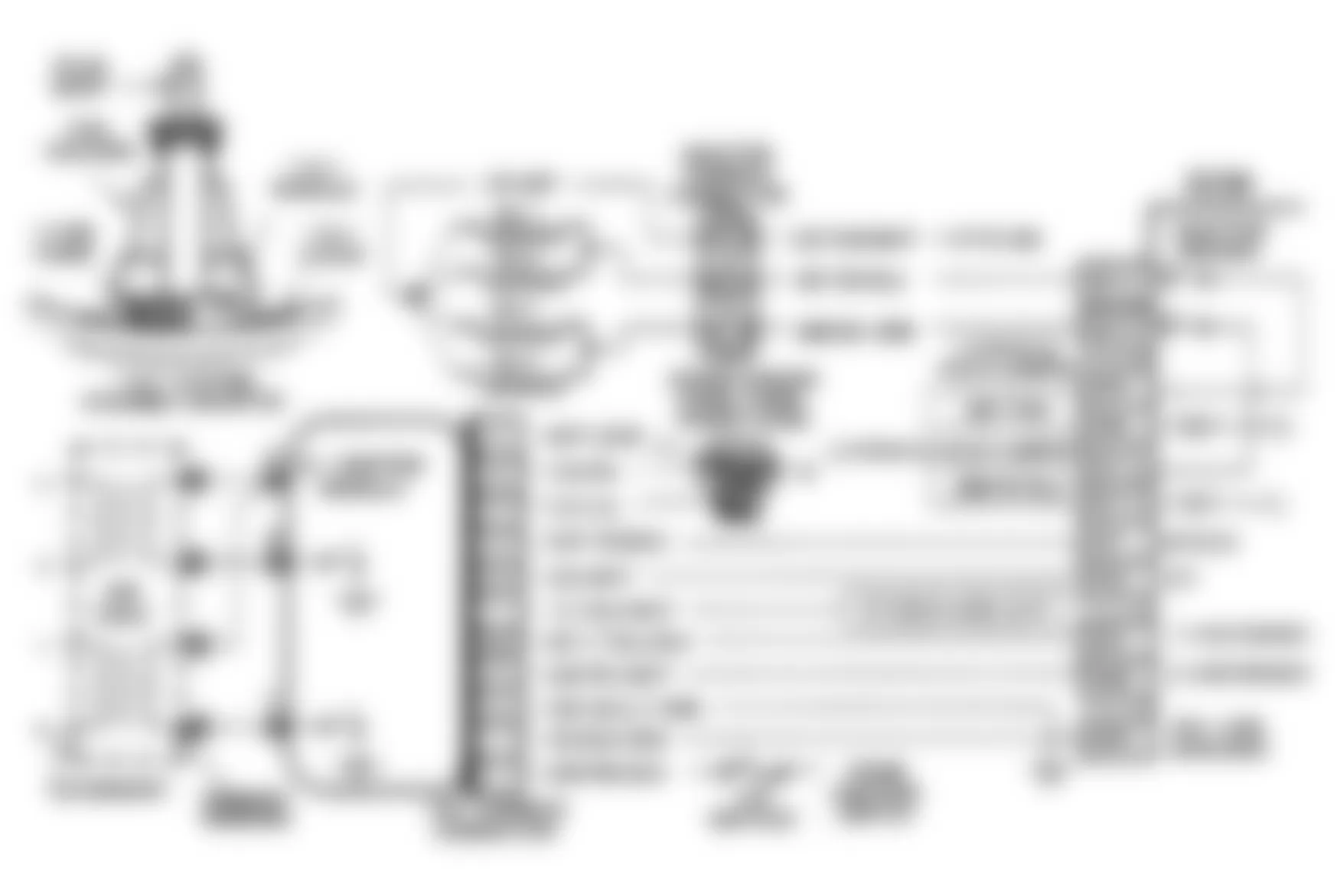
Fig. 19: Buick Skylark 1991 - Component Locations - Code 26, Schematic, Quad-Driver Error N Body


Buick Skylark 1991 - CODE 26, W BODY, QUAD-DRIVER ERROR
The control module controls most components with electronic switches completing a ground circuit when actuated. These switches are arranged in groups of 4, called Quad-Driver Modules (QDM's), which can independently control up to 4 outputs (control module terminals). When an output is actuated, the terminal is grounded and its voltage normally will be low. When an output is off, its terminal voltage normally will be high, except for the TCC, which depends on the brake and 2nd gear TCC switches.
QDM's are fault protected. If a relay or solenoid coil is shorted, having very low resistance, or if control side of circuit is shorted to voltage, it would allow too much current into QDM. The QDM senses this and turns the output off, or its internal resistance increases to limit current flow and protect the QDM. The result is high output terminal voltage when it should be low. If the circuit from battery voltage or the component is open, or the control side of circuit is shorted to ground, terminal voltage will be low, even when output is turned off. Either of these conditions is considered to be a QDM fault.
The control module ignores the fault line signal from QDM 3 to prevent false setting of Code 26 due to brake or 2nd gear TCC series switches. As a result, QDM 3 circuit problems will not cause a Code 26 although the circuits are fault protected and operate the same as QDMs 1 and 2.
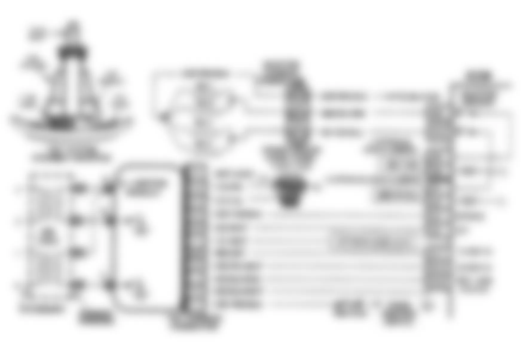
Fig. 23: Buick Skylark 1991 - Component Locations - Code 26, Schematic, Quad-Driver Error W Body


Buick Skylark 1991 - CODE 26, L BODY, QUAD-DRIVER CIRCUIT
The ECM controls most components with electronic switches completing a ground circuit when actuated. These switches are arranged in groups of 4, called Quad-Driver Modules (QDMs), which can independently control up to 4 outputs (control module terminals). When an output is actuated, the terminal is grounded and its voltage normally will be low. When an output is off, its terminal voltage will normally be high.
QDMs are fault protected. If a relay or solenoid coil is shorted, having very low resistance, or if control side of circuit is shorted to voltage, it would allow too much current into QDM. The QDM senses this and turns the output off, or its internal resistance increases to limit current flow and protect the QDM. The result is high output terminal voltage when it should be low. If the circuit from battery voltage or the component is open, or the control side of circuit is shorted to ground, terminal voltage will be low, even when output is turned off. Either of these conditions is considered to be a QDM fault.
Each QDM has a separate fault line to indicate the presence of a current fault to control module's central processor. A "Scan" tester displays the status of each of these fault lines as "low equals okay" or "high equals fault".
Buick Skylark 1991 - Diagnostic Aids
Intermittent faults must be continuously present for at least 20 seconds to cause Code 26 to set. QDM controlled circuits should be inspected for poor terminal contact or damaged harness. QDM faults can be detected as noted above and when outputs are on or off as follows:
- Open circuit or control circuit short to ground - output commanded off.
- Shorted device or control circuit short to voltage - output commanded on.
Fig. 27: Buick Skylark 1991 - Component Locations - Code 26, Schematic, L Body, Quad-Driver Circuit


Buick Skylark 1991 - CODE 32, W BODY, EGR SYSTEM ERROR
Digital EGR valve controls EGR flow through 2 different sized orifices which are normally closed by pintles held down by springs. Orifice No. 1 is smaller than No. 2. Independent solenoids lift the pintles off of the seats when ECM allows current to flow through solenoids by providing a ground for the solenoid windings. Electric circuit problems should result in a Code 26 setting. ECM test EGR operating by quickly opening the EGR pintles during stable idle conditions and monitoring changes in the MAP sensor vacuum signal. If change does not occur, this test is repeated several times before setting Code 32. Test occurs so quickly that it should not be noticeable to driver.
NOTE: Test numbers refer to test numbers on diagnostic chart.
- Code 26 indicates an electrical problem is likely. This can be diagnosed using Code 26 chart.
- This step actuates each solenoid and should result in a momentary drop in RPM or engine roughness if EGR flows at idle. The No. 2 solenoid should have a greater effect than the No. 1 solenoid.
Fig. 31: Buick Skylark 1991 - Component Locations - Code 32, Schematic, W Body, EGR System Error

Fig. 32: Buick Skylark 1991 - Component Locations - Code 32, Flow Chart, W Body, EGR System Error

Buick Skylark 1991 - CODE 32, W BODY, EGR SYSTEM ERROR USING TECH I
Digital EGR valve controls EGR flow through 2 different sized orifices which are normally closed by pintles held down by springs. Orifice No. 1 is smaller than No. 2. Independent solenoids lift the pintles off of the seats when ECM allows current to flow through solenoids by providing a ground for the solenoid windings. Electric circuit problems should result in a Code 26 setting. ECM test EGR operating by quickly opening the EGR pintles during stable idle conditions and monitoring changes in the MAP sensor vacuum signal. If change does not occur, this test is repeated several times before setting Code 32. Test occurs so quickly that it should not be noticeable to driver.
NOTE: Test numbers refer to test numbers on diagnostic chart.
- Code 26 indicates an electrical problem is likely. This can be diagnosed using Code 26 chart.
- This step actuates each solenoid and should result in a momentary drop in RPM or engine roughness if EGR flows at idle. The No. 2 solenoid should have a greater effect than the No. 1 solenoid.


Buick Skylark 1991 - CODE 33, MAP SENSOR SIGNAL VOLTAGE HIGH
NOTE: Test numbers refer to test numbers on diagnostic chart.
- This test confirms Code 33 and determines if it is the result of a hard failure or an intermittent condition. Code 33 will set when voltage signal reading is too high for greater than a precalibrated period of time, TPS voltage indicates throttle is closed and neither Code 21 or 22 is present.
- This step simulates conditions for a Code 34. If the control module recognizes and sets Code 34, low MAP signal, the control module and 5-volt reference and MAP signal circuits are not at fault. If ground circuit is shared with other sensors and ground circuit becomes open, additional codes related to these sensors may be set.
Buick Skylark 1991 - Diagnostic Aids
With the ignition switch in the ON position and the engine stopped, manifold pressure is equal to atmospheric pressure and the signal voltage will be high. Comparison of the BARO readings from a known good vehicle using the same sensor is a good way to check the accuracy of the suspected sensor. Readings should be the same within +/- .4 volt. Code 33 will result if ground circuit is open or MAP signal circuit is shorted to voltage or to 5-volt reference circuit.

NOTE: For shared sensor reference and shared sensor ground tie-offs, see appropriate diagram in WIRING DIAGRAMS.

Buick Skylark 1991 - CODE 34, MAP SENSOR SIGNAL VOLTAGE LOW
NOTE: Test numbers refer to test numbers on diagnostic chart.
- This confirms Code 34 and determines if code was caused by a hard failure or an intermittent fault. Code 34 will set when ignition is on and MAP signal voltage is low. On some systems, engine must be running to set code.
- Jumpering MAP signal to 5-volt reference at MAP harness connector will determine if sensor is at fault or if there is a problem with the control module or wiring.
- "Scan" tester may not display 12 volts. The important thing is the control module recognizes the voltage as greater than 4 volts (high MAP voltage signal), indicating the control module and MAP signal circuit are not at fault.
Buick Skylark 1991 - Diagnostic Aids
With the ignition switch in the ON position and the engine stopped, manifold pressure is equal to atmospheric pressure and the signal voltage will be high. Compare BARO readings with a known good vehicle using the same sensor is a good way to check the accuracy of the suspected sensor. Readings should be the same within +/- .4 volt. A Code 34 will also result if 5-volt reference and MAP signal circuits are open or shorted to ground.

NOTE: For shared sensor reference and shared sensor ground tie-offs, see appropriate diagram in WIRING DIAGRAMS.

Buick Skylark 1991 - CODE 35, IAC IDLE SPEED ERROR
Code 35 will set when closed throttle engine speed is 150 RPM greater or less than correct idle speed for 20 seconds.
NOTE: Test numbers refer to test numbers on diagnostic chart.
- IAC driver is used to extend and retract IAC valve. Movement is verified by an engine speed change. If no change in speed occurs, valve can be retested when removed from throttle body.
- Checks IAC movement quality from step 1). Between 700-1500 RPM, engine speed should change smoothly with each flash of the tester light in both extend and retract. If IAC valve is retracted beyond the control range (about 1500 RPM), it may take many flashes in the extend position before engine speed begins to drop. This is normal on certain engines. Fully extending the IAC may cause engine to stall. This may be normal.
- Steps 1) and 2) verified proper IAC valve operation while this step checks the IAC circuits. Each light on the node light should flash Red and Green while the IAC valve is cycled. While the sequence of color is not important if either light is off or does not flash Red and Green, check the circuits for faults beginning with poor terminal contacts.
Buick Skylark 1991 - Diagnostic Aids
A slow, unstable idle may be caused by a system problem that cannot be overcome by IAC. "Scan" counts will be greater than 60 if too low, and zero counts, if too high. If idle is too high, stop engine. Fully extend IAC with driver. Start engine. If idle speed is greater than 800 RPM, look for possible vacuum leaks.
Buick Skylark 1991 - System Too Lean
If air/fuel ratio is too lean, the idle speed may be either too high (check for vacuum leaks) or too low. Engine speed may vary up and down and disconnecting the IAC may not help. "Scan" and/or digital voltmeter (10-megohm) will read an oxygen sensor output less than 300 mv (.3 volt). Check for low fuel pressure or water in the fuel. A contaminated O2 sensor (caused by silicone) will produce lean air/fuel mixtures with an oxygen sensor output fixed greater than 800 mv (.8 volt). This may also set Code 45.
Buick Skylark 1991 - System Too Rich
If air/fuel ratio is too rich, idle speed will be too low and "Scan" tester counts will usually be greater than 80. The system may be obviously rich, with Black smoke from the tailpipe. "Scan" tester and/or voltmeter will read an oxygen sensor voltage signal fixed greater than 800 mv (.8 volt). Look for high fuel pressure or injectors leaking or sticking. Remove IAC and inspect bore for foreign material or evidence of IAC valve dragging the bore.
Buick Skylark 1991 - Throttle Body
Remove IAC and inspect bore for evidence of IAC valve dragging.
Buick Skylark 1991 - IAC Valve Connections
Inspect carefully for loose or corroded connections.
Buick Skylark 1991 - PCV Valve
An incorrect PCV valve may cause incorrect idle speed.
Fig. 39: Buick Skylark 1991 - Component Locations - Code 35, Schematic, IAC Idle Speed Error

Fig. 40: Buick Skylark 1991 - Component Locations - Code 35, Flow Chart, IAC Idle Speed Error

Buick Skylark 1991 - CODE 35, IAC IDLE SPEED ERROR USING TECH I
Code 35 will set when closed throttle engine speed is 150 RPM greater or less than correct idle speed for 20 seconds.
NOTE: Test numbers refer to test numbers on diagnostic chart.
- The Tech 1 RPM control mode is used to extend and retract the IAC valve. Movement is verified by an engine speed change. If no change in speed occurs, valve can be retested when removed from throttle body. If IAC valve is retracted beyond the control range (about 1500 RPM), it may take many flashes in the extend position before engine speed begins to drop. This is normal on certain engines. Fully extending the IAC may cause engine to stall. This may be normal.
- This test uses the Tech 1 to command the IAC controlled idle speed. The control module issues commands to obtain the requested idle speed. Each light on the node light should flash Red and Green while the IAC valve is cycled. While the sequence of color is not important if either light is off or does not flash Red and Green, check the circuits for faults beginning with poor terminal contacts.
Buick Skylark 1991 - Diagnostic Aids
A slow, unstable idle may be caused by a system problem that cannot be overcome by IAC. "Scan" counts will be greater than 60 if too low, and zero counts, if too high. If idle is too high, stop engine. Fully extend IAC with driver. Start engine. If idle speed is greater than 800 RPM, look for possible vacuum leaks.
Buick Skylark 1991 - System Too Lean
If air/fuel ratio is too lean, the idle speed may be either too high (check for vacuum leaks) or too low. Engine speed may vary up and down and disconnecting the IAC may not help. "Scan" and/or digital voltmeter (10-megohm) will read an oxygen sensor output less than 300 mv (.3 volt). Check for low fuel pressure or water in the fuel. A contaminated O2 sensor (caused by silicone) will produce lean air/fuel mixtures with an oxygen sensor output fixed greater than 800 mv (.8 volt). This may also set Code 45.
Buick Skylark 1991 - System Too Rich
If air/fuel ratio is too rich, idle speed will be too low and "Scan" tester counts will usually be greater than 80. The system may be obviously rich, with Black smoke from the tailpipe. "Scan" tester and/or voltmeter will read an oxygen sensor voltage signal fixed greater than 800 mv (.8 volt). Look for high fuel pressure or injectors leaking or sticking. Remove IAC and inspect bore for foreign material or evidence of IAC valve dragging the bore.
Buick Skylark 1991 - Throttle Body
Remove IAC and inspect bore for evidence of IAC valve dragging.
Buick Skylark 1991 - IAC Valve Connections
Inspect carefully for loose or corroded connections.
Buick Skylark 1991 - PCV Valve
An incorrect PCV valve may cause incorrect idle speed.


Buick Skylark 1991 - CODE 41, 1X REFERENCE CIRCUIT
The ignition module sends a signal to ECM once per revolution to indicate crankshaft position. The ECM uses this information to determine when to pulse injectors for cylinders No. 2 and 3. This signal can be described as a synchronization signal and is called 1X reference, because it occurs one time per revolution.
The ignition module applies 5 volts from terminal G to ECM terminal BC5 (L & N Body) or C11 (W Body) and in effect, switches this circuit to ground for a short period of time, 125 degrees before TDC of cylinders No. 2 and 3. Code 41 is set if ECM receives (8) 2X reference pulses without a 1X reference pulse. When Code 41 is present, ECM pulses injectors in the simultaneously mode.
NOTE: Test numbers refer to test numbers on diagnostic chart.
- This determines if ECM recognizes a fault. If a Code 41 is not set here, problem is intermittent and could be caused by a loose connection.
- This step simulates 1X signal.If circuit and ECM are okay, ECM should recognize the voltage drop as test light probe is removed. This step will only give accurate results if:
- Chart sequence is used (ignition off or ignition on).
- "Scan" tester is set to 1X reference.
- Terminal "G" is contacted using test light probe.
The ECM will only recognize up to 4 simulated 1X pulses under this test condition.
3) If ECM did not recognize simulation of 1X signal, circuit No. 969 (L and W Bodies) or No. 647 (N Body) may be open or shorted to ground or voltage. If circuit is okay, ECM is faulty.
4) Step 2 indicated 1X circuit is okay and ECM is capable of recognizing simulated 1X reference pulse. This indicates either a poor connection at ignition module terminal "G" or a faulty ignition module caused Code 41 to occur.
Buick Skylark 1991 - Diagnostic Aids
An intermittent may be caused by a poor connection, rubbed through wire insulation or a wire broken inside the insulation. Inspect ECM harness 1X connector terminal and ignition module terminal "G" for improperly formed or damaged terminals, poor terminal to wire connection and damaged harness. Code 41 will set if a 1988 ignition module is installed.
Fig. 43: Buick Skylark 1991 - Component Locations - Code 41, Schematic, L Body, 1X Reference Circuit

Fig. 44: Buick Skylark 1991 - Component Locations - Code 41, Schematic, N Body, 1X Reference Circuit
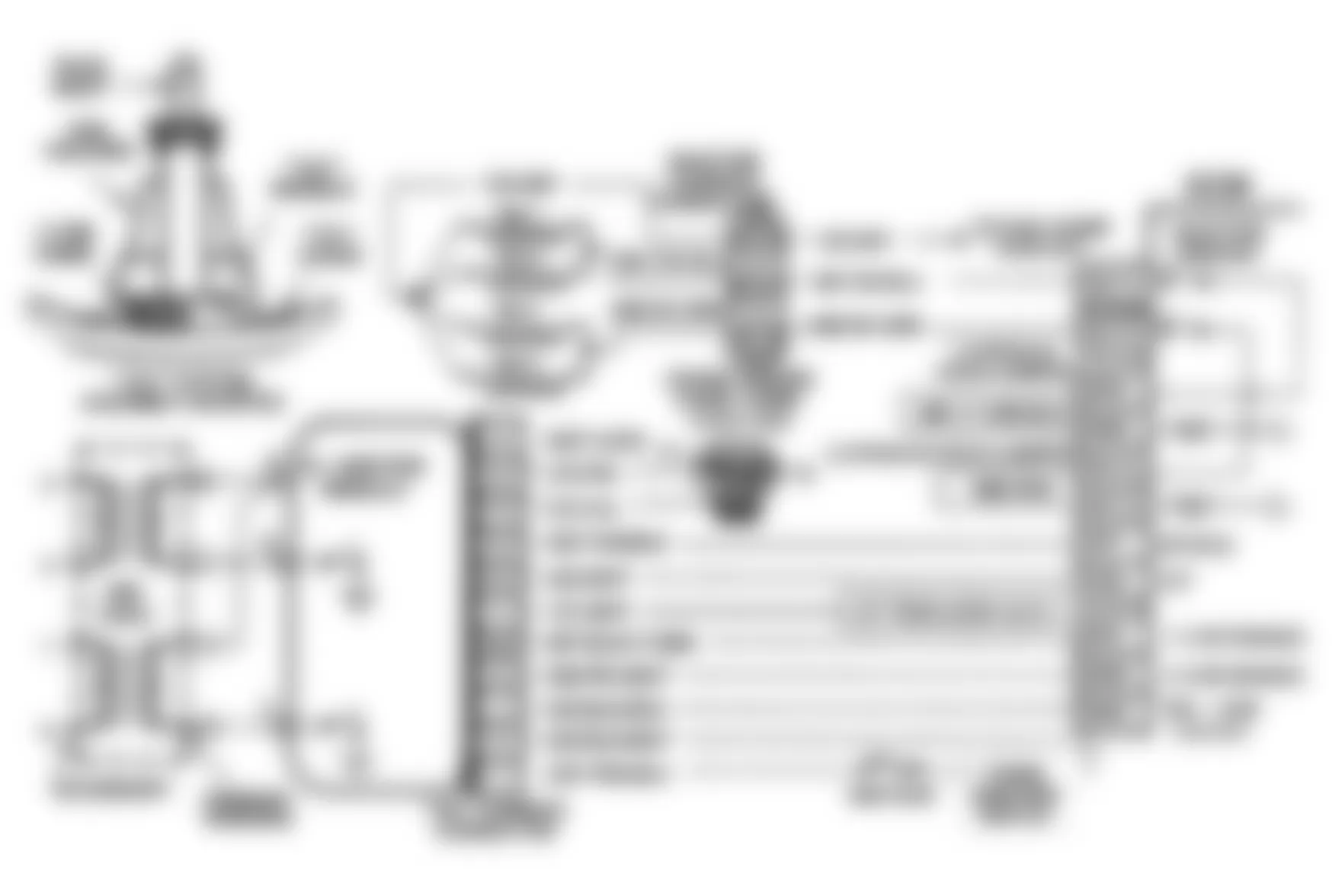
Fig. 45: Buick Skylark 1991 - Component Locations - Code 41, Schematic, W Body, 1X Reference Circuit

Fig. 46: Buick Skylark 1991 - Component Locations - Code 41, Flow Chart, (All) 1X Reference Circuit

Buick Skylark 1991 - CODE 42, EST CIRCUIT OPEN OR GROUNDED
Code 42 indicates the ECM has seen an open or short to ground in HEI EST or by-pass circuit.
NOTE: Test numbers refer to test numbers on diagnostic chart.
- Checks if ECM recognizes a fault. If a Code 42 is not set here, an intermittent problem exists and could be caused by a loose connection.
- With ECM disconnected, ohmmeter should indicate less than 500 ohms, which is normal resistance for the ignition module. A higher resistance indicates a fault in circuit No. 423, poor ignition module connection or faulty ignition module.
- If test light was illuminated when connected from 12 volts to ECM harness by-pass terminal either circuit No. 423 is shorted to ground or ignition module is faulty.
- Checks if ignition module switches when bypass circuit is energized by 12 volts through test light. If ignition module switches, ohmmeter reading should switch from less than 500 ohms to greater than 8000 ohms.
- Disconnecting ignition module should cause ohmmeter to indicate as if it were monitoring an open circuit (infinite reading). If ohmmeter reads anything other than infinity, circuit No. 423 is shorted to ground.
Buick Skylark 1991 - Diagnostic Aids
An intermittent may be caused by a poor connection, rubbed through wire insulation or wire broken inside insulation. Inspect ECM harness connectors for backed-out by-pass or EST terminals, improper mating, broken locks, improperly formed or damaged terminals, poor terminal-to-wire connection or damaged harness.


Buick Skylark 1991 - CODE 43, ESC ERROR WITHOUT ESC MODULE
Code 43 indicates the ECM has seen high or low voltage at circuit No. 496 for longer than 5 seconds with the engine running.
NOTE: Test numbers refer to test numbers on diagnostic chart.
- If conditions for test as described above are being met, Code 43 will currently set and the "SES" light will be illuminated.
- The ECM has a 5-volt pull-up resistor, which should be present at the knock sensor terminal.
- This test determines if internal resistance of knock sensor is within an acceptable range.
Buick Skylark 1991 - Diagnostic Aids
Check circuit No. 496 for a potential short or open to ground. Also check for proper installation of MEM-CAL. Mechanical engine knock can cause a knock sensor signal. Abnormal engine noise must be corrected before using this chart.
NOTE: Code 43 circuit diagram and flow chart has been updated by Technical Service Bulletin No. 91-6-6, dated 8/24/90.
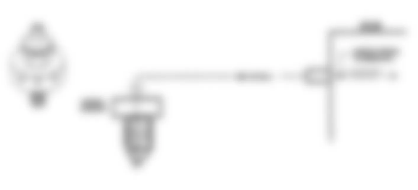
Fig. 51: Buick Skylark 1991 - Component Locations - Code 43, Schematic, ESC Error Without ESC Module
Buick Skylark 1991 - CODE 44, LEAN EXHAUST INDICATION
Oxygen sensor acts like an open sensor circuit and produces no voltage when exhaust temperature is less than 600?F (316?C). An open sensor circuit or cold sensor causes "open loop" operation.
NOTE: Test numbers refer to test numbers on diagnostic chart.
- Checks to see if O2 sensor is registering a lean condition. Code 44 is set when O2 sensor voltage signal at control module is low (less than .3 volt) for a precalibrated period and system is operating in "closed loop".
Buick Skylark 1991 - Diagnostic Aids
Using the "Scan" tester, observe the Block Learn Memory (BLM) value at different RPMs. If conditions for a Code 44 exist, the block learn value will be around 150.
Buick Skylark 1991 - O2 Sensor Wire
O2 sensor wire may be mispositioned and laying against the exhaust manifold. Check for ground between sensor and wire connector.
Buick Skylark 1991 - Fuel Contamination
Water, even small amounts, near the in-tank fuel pump inlet can be delivered to the injector. The water may cause a lean exhaust and set Code 44.
Buick Skylark 1991 - Fuel Pressure
System will be lean if fuel pressure is low. It may be necessary to monitor fuel pressure while driving vehicle. For fuel pressure checking procedure, see BASIC TESTING article in this section.
Buick Skylark 1991 - Exhaust Leaks
If the exhaust system has large leaks, exhaust system negative pressure pulses can cause outside air to be drawn into the system and past the O2 sensor. Vacuum or crankcase leaks can also cause a lean condition.
Buick Skylark 1991 - Misfire Or Stall
If engine misfires or stalls while vehicle is moving, including running out of fuel, a Code 44 may set. If Code 44 is intermittent, see INTERMITTENTS in TESTS W/O CODES article in this section.
Fig. 53: Buick Skylark 1991 - Component Locations - Code 44, Schematic, Lean Exhaust Indication

Fig. 54: Buick Skylark 1991 - Component Locations - Code 44, Flow Chart, Lean Exhaust Indication

Buick Skylark 1991 CODE 44 ECM TERMINAL & CIRCUIT WIRING IDENTIFICATION
Application ECM Terminal Wire Color L Body O2 Signal GE14 Black O2 Ground GE15 Tan N Body O2 Signal GE14 Purple O2 Ground GE15 Tan W Body O2 Signal A16 Purple O2 Ground A22 Tan
Buick Skylark 1991 - CODE 45, RICH EXHAUST INDICATION
Oxygen sensor acts like an open sensor circuit and produces no voltage when exhaust temperature is less than 600?F (316?C). An open sensor circuit or cold sensor causes "open loop" operation.
Code 45 indicates a rich exhaust and diagnosis should begin with these items: fuel pressure, leaking injector, HEI shielding (ground), vapor canister fuel saturation, coolant sensor, MAP sensor, O2 sensor contamination and TPS intermittent output.
NOTE: Test numbers refer to test numbers on diagnostic chart.
- Test checks to see if O2 sensor is registering a rich condition. Code 45 is set when vehicle is at operating temperature (in "closed loop"), throttle angle is greater than idle, O2 sensor signal at control module is greater than .7 volt for a precalibrated period and time since engine start is one minute or more.
Buick Skylark 1991 - Diagnostic Aids
If other codes of lower number are set with Code 45, use those charts first. Malfunction in the MAP or TPS sensor circuits can cause a Code 45 to set. If other codes are not set, Code 45, rich exhaust, is most likely caused by one of the following:
Buick Skylark 1991 - Fuel Pressure High
If fuel pressure is too high, air/fuel ratios will be rich. For fuel pressure checking procedure, see BASIC TESTING article in this section. The control module can compensate for slight increases but if air/fuel ratio becomes too rich a Code 45 will be set.
Buick Skylark 1991 - Ignition Ground
If an open occurs at circuit No. 453, HEI induced electrical "noise" may result, causing simulated reference pulses to be picked up by control module on reference line of EST harness. Additional pulses result in a higher than actual engine speed signal. The control module will increase injector pulse width ("on" time) to match the increased RPM signal. "Scan" tester will show higher than actual RPM, which can help in diagnosing this problem.
Buick Skylark 1991 - Evaporative Fuel Canister
Fuel saturation of the charcoal canister will cause a rich air/fuel ratio. If full of fuel, check canister control valves and hoses.
Buick Skylark 1991 - MAP Sensor
An output that causes the control module to sense a higher than normal manifold pressure (low vacuum) can cause the system to go rich. Disconnecting the MAP sensor will allow the control module to substitute a fixed value for the MAP sensor. If the condition disappears, substitute a different MAP sensor and continue testing.
Buick Skylark 1991 - TPS
An intermittent TPS output will cause the system to operate rich due to a false indication of engine acceleration.
Buick Skylark 1991 - O2 Sensor Contamination
O2 sensor contamination, caused by silicone in certain fuels or use of improper RTV sealant, may cause a White powdery coating to cover the exterior of the O2 sensor. The false high signal voltage (low oxygen content sensed) produced is interpreted by the control module as a rich mixture, causing the control module to set Code 45.
Buick Skylark 1991 - EGR Problem
EGR valve sticking open at idle is usually accompanied by a rough idle and/or stalling. Also check for shorted or leaking injector, or fuel contaminated oil. If Code 45 is intermittent, see INTERMITTENTS in TESTS W/O CODES article in this section.
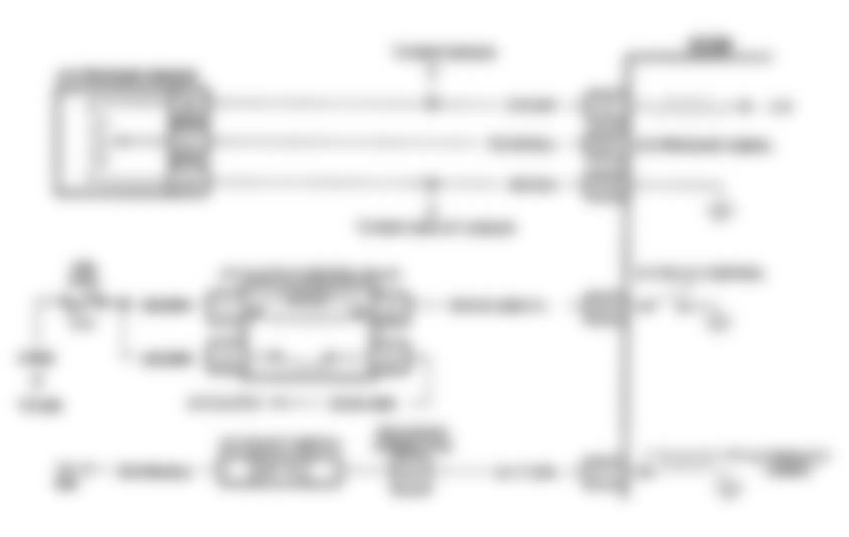
Fig. 55: Buick Skylark 1991 - Component Locations - Code 45, Schematic, Rich Exhaust Indication

Fig. 56: Buick Skylark 1991 - Component Locations - Code 45, Flow Chart, Rich Exhaust Indication

Buick Skylark 1991 CODE 45 ECM TERMINAL & CIRCUIT WIRING IDENTIFICATION
Application ECM Terminal Wire Color L Body O2 Signal GE14 Black O2 Ground GE15 Tan N Body O2 Signal GE14 Purple O2 Ground GE15 Tan W Body O2 Signal A16 Purple O2 Ground A22 Tan
Buick Skylark 1991 - CODE 47, PCM-BCM DATA LOSS
Check for momentary loss of BCM's 7 volts on circuit No. 807, 750 or 555. Also, ensure that MEM-CAL is properly installed.
Buick Skylark 1991 - CODE 51, FAULTY PROM/MEM-CAL
Check that all pins are fully inserted in socket. If okay, replace PROM/MEM-CAL, clear memory and recheck. If Code 51 reappears, replace control module.
Buick Skylark 1991 - CODE 52, FAULTY CALPAK
Check that all pins are fully inserted in socket. If okay, replace CALPAK, clear memory and recheck. If Code 51 reappears, replace control module.
Buick Skylark 1991 - CODE 53, SYSTEM OVERVOLTAGE
This code indicates a basic charging system problem. Code 53 will set when voltage at control module terminal is greater or less than specification for a precalibrated time. If voltage at ECM battery voltage terminal is not within specification, check and repair charging system.
Buick Skylark 1991 CHARGING SYSTEM SPECIFICATIONS
Application Minimum Charge Maximum Charge 2.3L 10.0 17.1
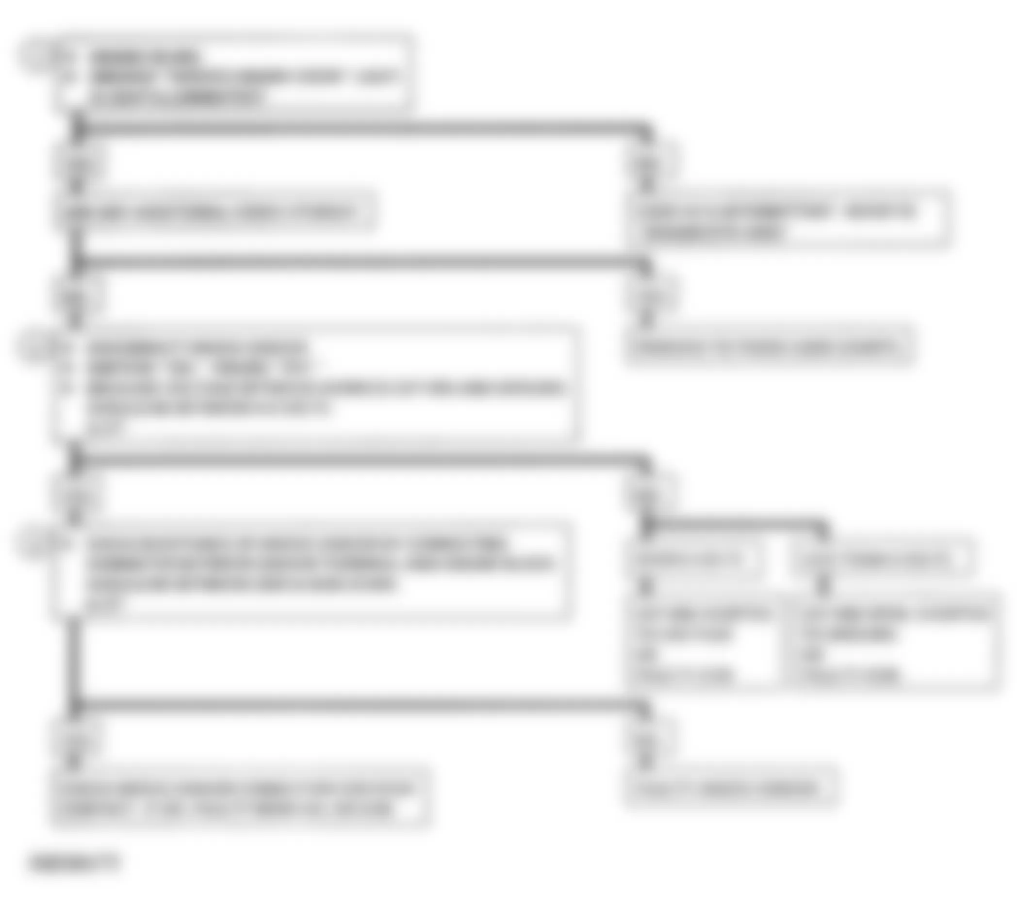
Fig. 57: Buick Skylark 1991 - Component Locations - Code 53, Flow Chart, System Overvoltage

Buick Skylark 1991 - CODE 65, L, N & W BODIES, INJECTOR CURRENT LOW
The ECM has 2 injector driver circuits, each controlling a pair of injectors (1 and 4, or 2 and 3). The ECM monitors current of each injector driver circuit by measuring voltage drop through a fixed resistor. The ECM is able to control voltage drop. The current through each driver is allowed to rise to a peak of 4 amps, enabling injectors to open quickly, and is then reduced to one amp, holding them open. This is called, "peak and hold". If current can't reach a 4-amp peak, Code 65 is set. This code is also set if an injector driver circuit is shorted to voltage.
NOTE: Test numbers refer to test numbers on diagnostic chart.
- The following conditions must be present to set a Code 65:
- The 4-amp injector current was not reached on each circuit.
- Battery voltage greater than 9 volts.
- Injectors pulsed on longer than calibrated pulse width.
- The above conditions met for 20 seconds.
- Checks ECM and harness wiring to 3-terminal injector harness connector.
- This tests for open injector harness or injector.
NOTE: Although shorted harness or injector (zero ohms) will not set a Code 65, problem should be corrected if discovered. - Results of step 2) will determine which branch to follow on Code 65 flow chart (2 of 2).
- Each harness was confirmed as being okay in steps 2) and 3). This test will check remainder of circuit from injectors to ECM.
- Identifies cause of high resistance found in step 3). A short or low resistance will not cause Code 65, but should be corrected.
- This tests for grounded "peak and hold" jumpers. This condition would allow injectors to pulse, but would NOT allow "peak and hold" operation as current would not flow through resistor in ECM.
- This checks for short to voltage in injector driver circuits.
- Determines if injector driver circuits are shorted to ground.
- This checks the output at the ECM to determine if injector driver circuits are okay.
- Checks for proper continuity of "peak and hold" jumpers circuits.
Buick Skylark 1991 - Diagnostic Aids
An open in injector drive or "peak and hold" circuits, or ECM drive circuits shorted to voltage will cause a Code 65 to be set and also cause misfire due to an inoperative pair of injectors. "Peak and hold" circuits shorted to ground will cause a Code 65 to set, while allowing injectors to pulse. An intermittent problem would have to be present for at least 20 seconds to set Code 65.
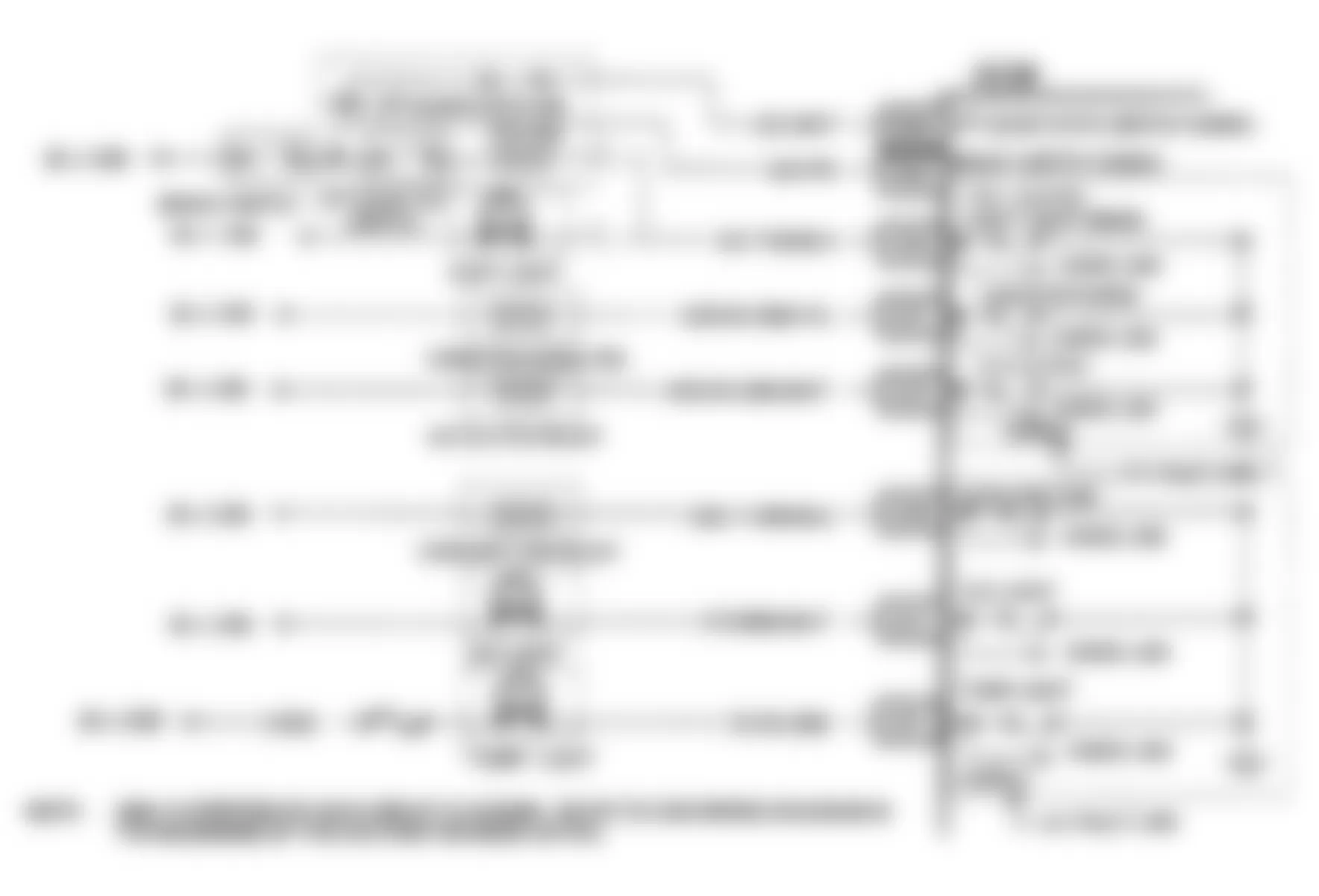
Fig. 58: Buick Skylark 1991 - Component Locations - Code 65, Schematic, L Body, Injector Current Low
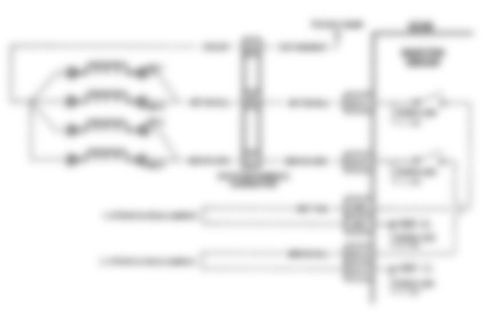
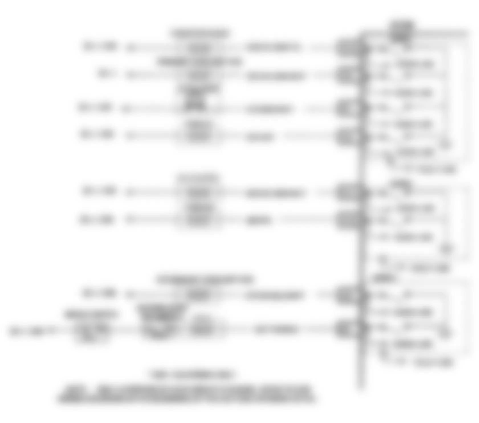
Fig. 59: Buick Skylark 1991 - Component Locations - Code 65, Schematic, N Body, Injector Current Low
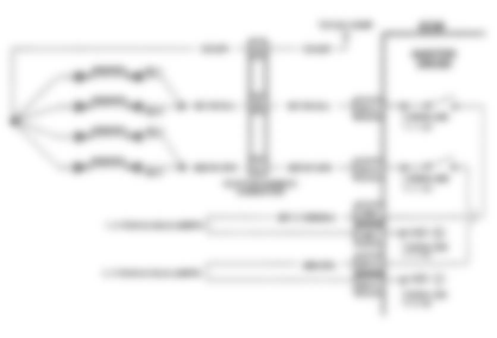
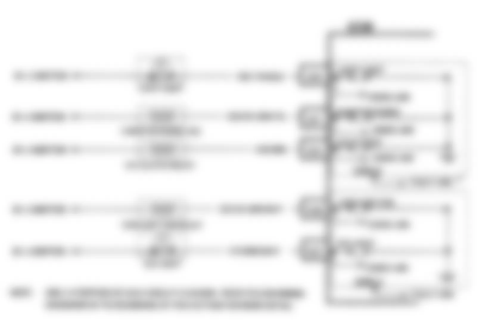
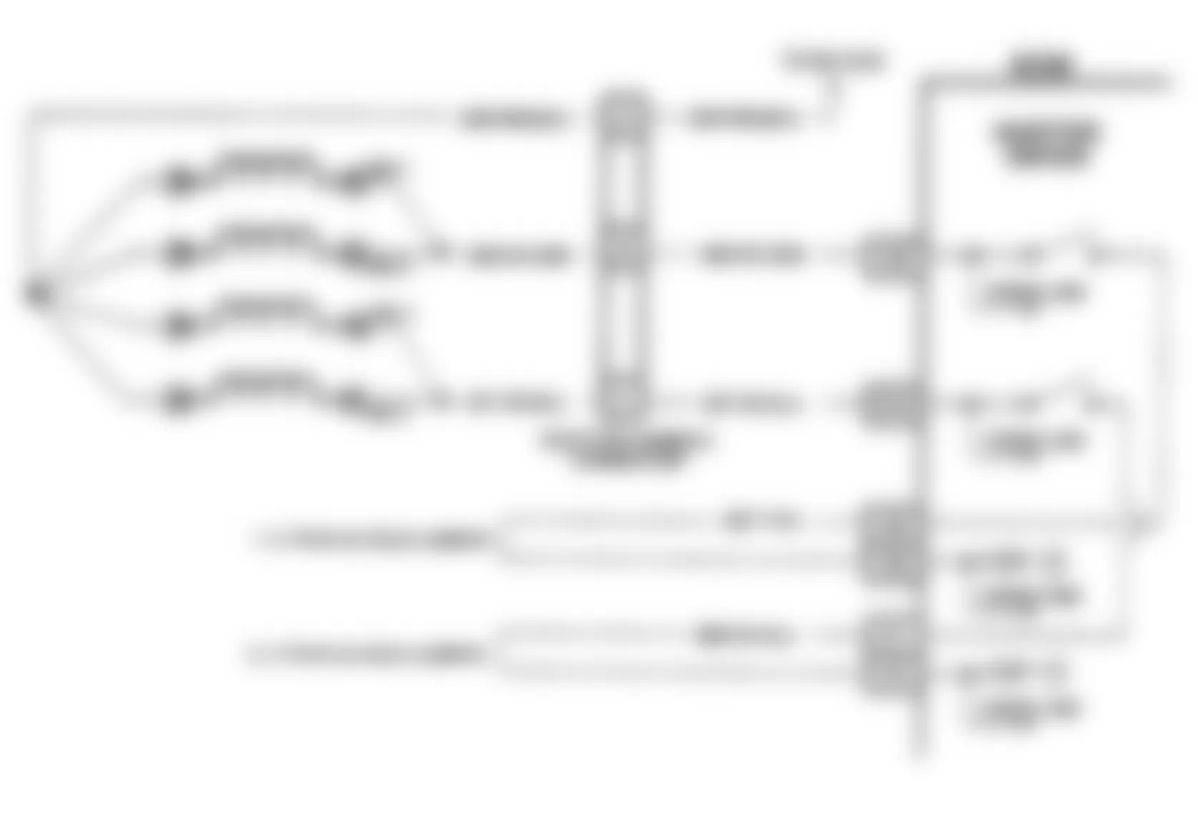
Fig. 60: Buick Skylark 1991 - Component Locations - Code 65, Schematic, W Body, Injector Current Low


Buick Skylark 1991 - CODE 66, L, N & W BODIES, A/C PRESSURE SENSOR
The A/C pressure sensor responds to changes in A/C refrigerant system high side pressure. The ECM uses A/C compressor load input to determine engine idle speed. Sensor uses a 5-volt reference signal from the ECM and returns an input signal to the ECM on a separate line. Low pressure (zero psi) will return a signal of about .1 volt. High pressure will return a signal of about 4.9 volts. ECM will disable A/C if code 66 is present.
NOTE: Test numbers refer to test numbers on diagnostic chart.
- Checks voltage signal from A/C pressure sensor to ECM.
- Checks to see if high signal is from a shorted sensor or a short to voltage in the circuit. Normally, disconnecting the sensor would make a normal circuit go to nearly zero volts.
- Checks to see if low voltage signal is from the sensor or circuit. Jumpering the sensor signal circuit to 5-volt reference checks the circuit, connections and ECM.
- Checks to see if the low voltage signal was due to an open in the sensor circuit or in the 5-volt reference since the prior step eliminated the pressure sensor.
Buick Skylark 1991 - Diagnostic Aids
Code 66 sets when signal voltage falls outside the normal sensor range and is not due to a A/C system problem. If problem is intermittent, check for opens or shorts in harness or poor connections. If okay, replace pressure sensor. If code resets, replace ECM.
Fig. 63: Buick Skylark 1991 - Component Locations - Code 66, Schematic, L Body, A/C Pressure Sensor
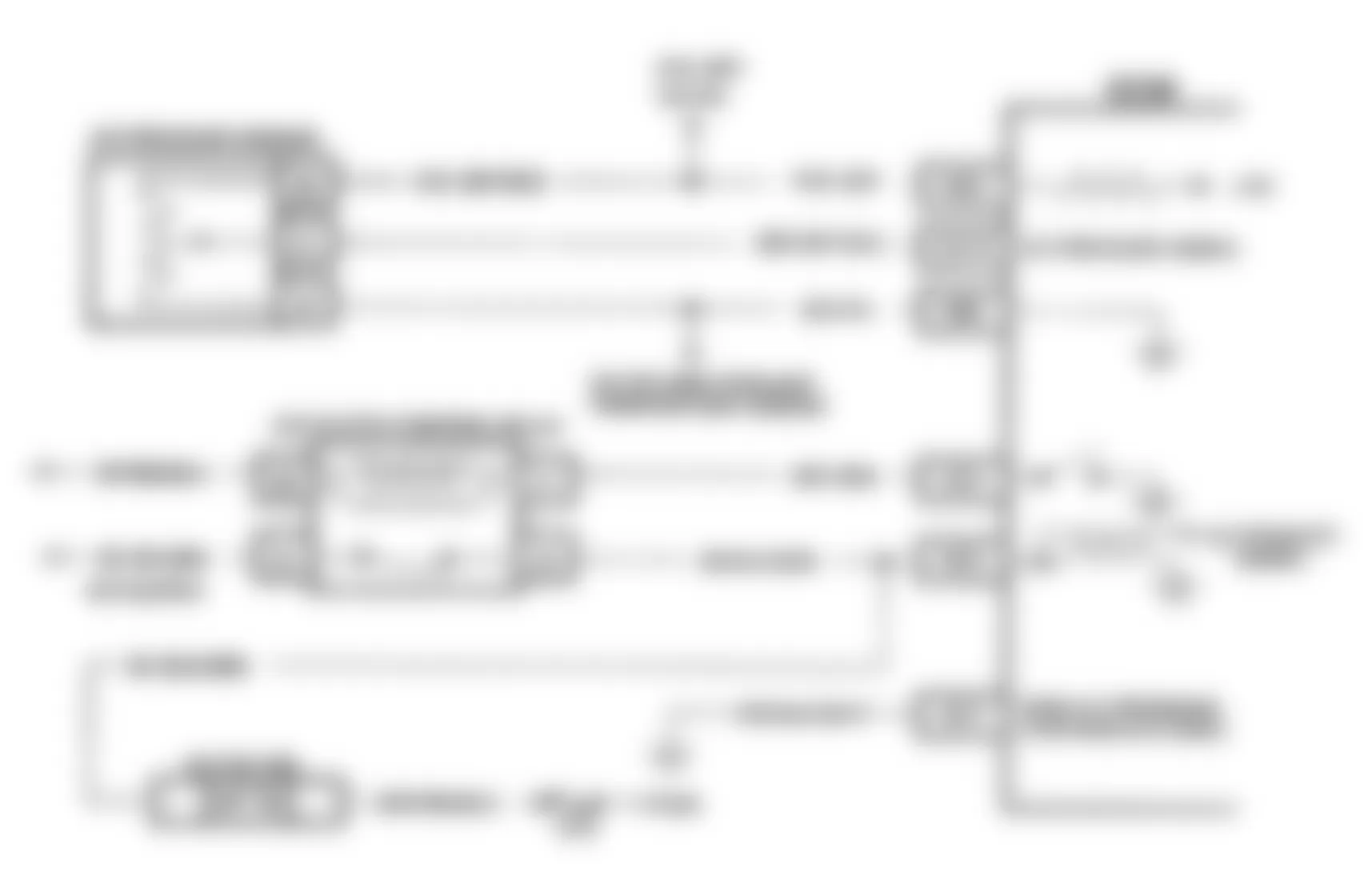
Fig. 64: Buick Skylark 1991 - Component Locations - Code 66, Schematic, N Body, A/C Pressure Sensor
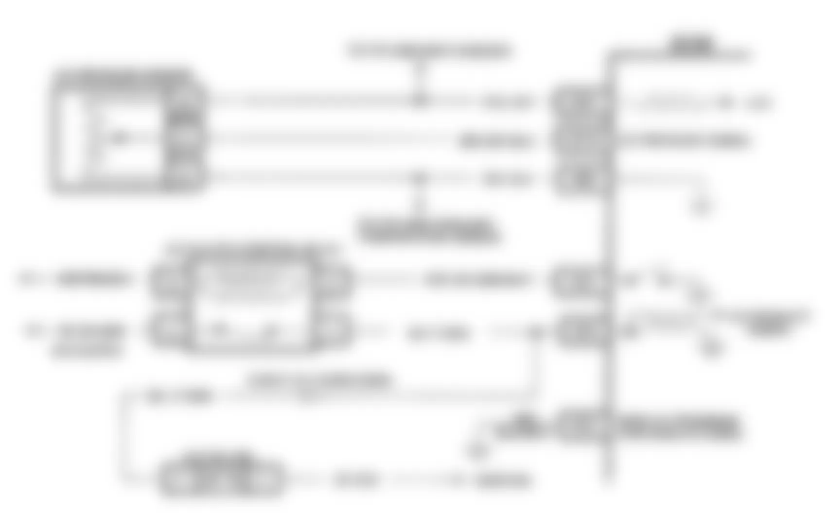
Fig. 65: Buick Skylark 1991 - Component Locations - Code 66, Schematic, W Body, A/C Pressure Sensor