
Chevrolet Cutaway G3500 2004 - 2004 ACCESSORIES & EQUIPMENT Wiring Systems, Component Locator - Express & Savana
Chevrolet Cutaway G3500 2004 - Master Electrical Component List
Chevrolet Cutaway G3500 2004 Master Electrical Component List
Name Location Locator View Connector End View 1-2 Shift Solenoid (1-2 SS) Valve Internal to the transmission Automatic Transmission Electronic Component Views in Automatic Transmission - 4L60-E
or in
Automatic Transmission Electronic Component Views in Automatic Transmission - 4L80-EAutomatic Transmission Related Connector End Views in Automatic Transmission - 4L60-E
or in
Automatic Transmission Related Connector End Views in Automatic Transmission - 4L80-E 2-3 Shift Solenoid (2-3 SS) Valve Internal to the transmission Automatic Transmission Electronic Component Views in Automatic Transmission - 4L60-E
or in
Automatic Transmission Electronic Component Views in Automatic Transmission - 4L80-EAutomatic Transmission Related Connector End Views in Automatic Transmission - 4L60-E
or in
Automatic Transmission Related Connector End Views in Automatic Transmission - 4L80-E 3-2 Shift Solenoid (3-2 SS) Valve (4L60-E) Internal to the transmission Automatic Transmission Electronic Component Views in Automatic Transmission - 4L60-E Automatic Transmission Related Connector End Views in Automatic Transmission - 4L60-E A/C Compressor Clutch (C60) On the front of the A/C compressor HVAC Component Views in HVAC Systems - Manual HVAC Connector End Views in HVAC Systems - Manual A/C High Pressure Switch (C60) On the rear of the A/C compressor HVAC Component Views in HVAC Systems - Manual HVAC Connector End Views in HVAC Systems - Manual A/C Low Pressure Switch (C60) Right rear side of the engine compartment, on the side of the accumulator HVAC Component Views in HVAC Systems - Manual HVAC Connector End Views in HVAC Systems - Manual A/T Shift Lock Control Solenoid Attached to the right side of the steering column Automatic Transmission Shift Lock Control Component Views in Shift Lock Control Automatic Transmission Shift Lock Control Connector End Views in Shift Lock Control Accelerator Pedal Position (APP) Sensor (JL4) Left lower side of the I/P, above the accelerator pedal Engine Controls Component Views in Engine Controls - 4.8L, 5.3L and 6.0L Engine Controls Connector End Views in Engine Controls - 4.8L, 5.3L and 6.0L Access Panel Actuator - Left Front Side Front (PRP) At the left front access panel Body Rear End Component Views in Body Rear End Body Rear End Connector End Views in Body Rear End Access Panel Actuator - Left Front Side Rear (PRP) At the left front access panel Body Rear End Component Views in Body Rear End Body Rear End Connector End Views in Body Rear End Access Panel Actuator - Left Rear Side Front (PRP) At the left rear access panel Body Rear End Component Views in Body Rear End Body Rear End Connector End Views in Body Rear End Access Panel Actuator - Left Rear Side Rear (PRP) At the left rear access panel Body Rear End Component Views in Body Rear End Body Rear End Connector End Views in Body Rear End Access Panel Actuator - Right Side Front (PRP) At the right access panel Body Rear End Component Views in Body Rear End Body Rear End Connector End Views in Body Rear End Access Panel Actuator - Right Side Rear (PRP) At the right access panel Body Rear End Component Views in Body Rear End Body Rear End Connector End Views in Body Rear End Air Temperature Actuator Lower right side of the I/P, attached to the HVAC module HVAC Component Views in HVAC Systems - Manual HVAC Connector End Views in HVAC Systems - Manual Air Temperature Actuator - Auxiliary (C69) In the LR of the passenger compartment, attached to the auxiliary HVAC module HVAC Component Views in HVAC Systems - Manual HVAC Connector End Views in HVAC Systems - Manual Ambient Air Temperature Sensor (DF5) Attached to the front center of the radiator support Stationary Windows Component Views in Stationary Windows Stationary Windows Connector End Views in Stationary Windows Antenna Attached to the RF fender Entertainment Component Views in Entertainment - Automatic Transmission Fluid Pressure Manual Valve Position Switch Internal to the transmission Automatic Transmission Electronic Component Views in Automatic Transmission - 4L60-E
or in
Automatic Transmission Electronic Component Views in Automatic Transmission - 4L80-EAutomatic Transmission Related Connector End Views in Automatic Transmission - 4L60-E
or in
Automatic Transmission Related Connector End Views in Automatic Transmission - 4L80-E Automatic Transmission Fluid Temperature (TFT) Sensor (4L60-E) Part of the Automatic Transmission Fluid Pressure Manual Valve Position Switch Automatic Transmission Electronic Component Views in Automatic Transmission - 4L60-E Automatic Transmission Related Connector End Views in Automatic Transmission - 4L60-E Automatic Transmission Fluid Temperature (TFT) Sensor (4L80-E) Internal to the transmission Automatic Transmission Electronic Component Views in Automatic Transmission - 4L80-E Automatic Transmission Related Connector End Views in Automatic Transmission - 4L80-E Automatic Transmission Input Shaft Speed (AT ISS) Sensor (4L80-E) Left side of the transmission Automatic Transmission Electronic Component Views in Automatic Transmission - 4L80-E Automatic Transmission Related Connector End Views in Automatic Transmission - 4L80-E Auxiliary Power Outlet 1 (w/o DT4) In the left center of the I/P Power Outlet Component Views in Power Outlets Power Outlet Connector End Views in Power Outlets Auxiliary Power Outlet 2 In the right center of the I/P Power Outlet Component Views in Power Outlets Power Outlet Connector End Views in Power Outlets Backup Lamp - Left (Passenger/Cargo) Attached to the left tail lamp assembly Lighting Systems Component Views in Lighting Systems - Backup Lamp - Right (Passenger/Cargo) Attached to the right tail lamp assembly Lighting Systems Component Views in Lighting Systems - Battery At the RF side of the engine compartment Power and Grounding Component Views Power and Grounding Connector End Views Blower Motor RR of the engine compartment, attached to the evaporator case HVAC Component Views in HVAC Systems - Manual HVAC Connector End Views in HVAC Systems - Manual Blower Motor - Auxiliary (C36/C69) In the LR of the passenger compartment, attached to the auxiliary HVAC module HVAC Component Views in HVAC Systems - Manual HVAC Connector End Views in HVAC Systems - Manual Blower Motor Resistor Assembly RR of the engine compartment, attached to the evaporator case HVAC Component Views in HVAC Systems - Manual HVAC Connector End Views in HVAC Systems - Manual Blower Motor Resistor Assembly - Auxiliary (C36/C69) In the LR of the passenger compartment, attached to the auxiliary HVAC module HVAC Component Views in HVAC Systems - Manual HVAC Connector End Views in HVAC Systems - Manual Blower Motor Switch - Auxiliary (C36 w/o C69) In the center of the I/P HVAC Component Views in HVAC Systems - Manual HVAC Connector End Views in HVAC Systems - Manual Body Control Module (BCM) Lower right side of the I/P Body Control System Component Views in Body Control System Body Control System Connector End Views in Body Control System Brake Fluid Level Switch (Heavy Duty) On the left lower side of the brake fluid reservoir Hydraulic Brakes Component Views in Hydraulic Brakes Hydraulic Brakes Connector End Views in Hydraulic Brakes Brake Pressure Differential Switch (Light Duty) Attached to the brake valve, near the front of the EBCM Hydraulic Brakes Component Views in Hydraulic Brakes Hydraulic Brakes Connector End Views in Hydraulic Brakes Camshaft Position (CMP) Sensor (4.3L) Part of the distributor, top rear of the engine Engine Controls Component Views in Engine Controls - 4.3L Engine Controls Connector End Views in Engine Controls - 4.3L Camshaft Position (CMP) Sensor (4.8L/5.3L/6.0L) At the top center rear of the engine Engine Controls Component Views in Engine Controls - 4.8L, 5.3L and 6.0L Engine Controls Connector End Views in Engine Controls - 4.8L, 5.3L and 6.0L Cellular Antenna (UE1) Attached to the right upper corner of the windshield Cellular Communication Component Views in Cellular Communication Cellular Communication Connector End Views in Cellular Communication Cellular Telephone Microphone (UE1) Attached to the LF of the roof panel Cellular Communication Component Views in Cellular Communication Cellular Communication Connector End Views in Cellular Communication Center High Mounted Stop Lamp (CHMSL) (Passenger/Cargo) At the top rear center of the vehicle Lighting Systems Component Views in Lighting Systems Lighting Systems Connector End Views in Lighting Systems Central Sequential Fuel Injection (Central SFI) (4.3L) Attached to the lower side of the intake manifold Engine Controls Component Views in Engine Controls - 4.3L Engine Controls Connector End Views in Engine Controls - 4.3L Chime Module (UL5) In the center of the I/P, attached to the radio connector Instrument Panel, Gages, and Console Component Views in Instrument Panel, Gages and Console Instrument Panel, Gages, and Console Connector End Views in Instrument Panel, Gages and Console Cigar Lighter (DT4) In the center of the I/P Power Outlet Component Views in Power Outlets Power Outlet Connector End Views in Power Outlets Courtesy/Reading Lamp - Front In the front of the roof panel Lighting Systems Component Views in Lighting Systems Lighting Systems Connector End Views in Lighting Systems Courtesy/Reading Lamp - Mid (Passenger/Cargo) In the center of the roof panel Lighting Systems Component Views in Lighting Systems Lighting Systems Connector End Views in Lighting Systems Courtesy/Reading Lamp - Rear (Passenger/Cargo) In the rear of the roof panel Lighting Systems Component Views in Lighting Systems Lighting Systems Connector End Views in Lighting Systems Crankshaft Position (CKP) Sensor (4.3L) Attached to the lower right front of the engine, near the crankshaft Engine Controls Component Views in Engine Controls - 4.3L Engine Controls Connector End Views in Engine Controls - 4.3L Crankshaft Position (CKP) Sensor (4.8L/5.3L/6.0L) Attached to the lower RR side of the engine, behind the starter Engine Controls Component Views in Engine Controls - 4.8L, 5.3L and 6.0L Engine Controls Connector End Views in Engine Controls - 4.8L, 5.3L and 6.0L Cruise Control Module (CCM) (K34 w/o JL4) In the left rear of the engine compartment, near the brake fluid reservoir Cruise Control Component Views in Cruise Control Cruise Control Connector End Views in Cruise Control Cruise Control ON/OFF Switch (K34) Part of the turn signal/multifunction switch Cruise Control Component Views in Cruise Control Cruise Control Connector End Views in Cruise Control Data Link Connector (DLC) Left lower side of the I/P, near the park brake pedal assembly Data Link Communications Component Views in Data Link Communications Data Link Communications Connector End Views in Data Link Communications Dome Lamp - Rear (Cargo) In the rear of the roof panel Lighting Systems Component Views in Lighting Systems Lighting Systems Connector End Views in Lighting Systems Dome Fluorescent Work Lamp - 1 (PRP w/UF2) Attached to the front of the roof panel Lighting Systems Component Views in Lighting Systems Lighting Systems Connector End Views in Lighting Systems Dome Fluorescent Work Lamp - 2 (PRP w/UF2) Attached to the rear of the roof panel Lighting Systems Component Views in Lighting Systems Lighting Systems Connector End Views in Lighting Systems Dome Fluorescent Work Lamp - LF (PRP w/UF2) Attached to the LF access panel Lighting Systems Component Views in Lighting Systems Lighting Systems Connector End Views in Lighting Systems Dome Fluorescent Work Lamp - LR (PRP w/UF2) Attached to the LR access panel Lighting Systems Component Views in Lighting Systems Lighting Systems Connector End Views in Lighting Systems Dome Fluorescent Work Lamp - RH (PRP w/UF2) Attached to the RH access panel Lighting Systems Component Views in Lighting Systems Lighting Systems Connector End Views in Lighting Systems Dome Fluorescent Work Lamp - Relay (PRP w/UF2) Attached to the left B-pillar Lighting Systems Component Views in Lighting Systems Lighting Systems Connector End Views in Lighting Systems Door Contact Plate - Left Side (E26 w/AU3) Attached to the left B-pillar Power Door Systems Component Views in Doors Power Door Systems Connector End Views in Doors Door Contact Plate - Right Side (Passenger/Cargo w/AU3) Attached to the right B-pillar Power Door Systems Component Views in Doors Power Door Systems Connector End Views in Doors Door Jamb Switch - LR Side (E26) Attached to the lower LR B-pillar Power Door Systems Component Views in Doors Power Door Systems Connector End Views in Doors Door Jamb Switch - RR Side (Passenger/Cargo) Attached to the lower RR B-pillar Power Door Systems Component Views in Doors Power Door Systems Connector End Views in Doors Door Latch Assembly - Cargo (Passenger/Cargo) Attached to the right cargo door latch, in the right cargo door Power Door Systems Component Views in Doors Power Door Systems Connector End Views in Doors Door Latch Assembly - Driver Attached to the driver door latch, in the driver door Power Door Systems Component Views in Doors Power Door Systems Connector End Views in Doors Door Latch Assembly - Passenger Attached to the front passenger door latch, in the front passenger door Power Door Systems Component Views in Doors Power Door Systems Connector End Views in Doors Door Lock Actuator - LR Side (E26/AU3) Attached to the LR door latch, in the LR door Power Door Systems Component Views in Doors Power Door Systems Connector End Views in Doors Door Lock Actuator - RR Side (Passenger/Cargo w/AU3) Attached to the RR door latch, in the RR door Power Door Systems Component Views in Doors Power Door Systems Connector End Views in Doors Door Lock Switch - Driver (AU3) Attached to the LF door accessory mount plate Power Door Systems Component Views in Doors Power Door Systems Connector End Views in Doors Door Lock Switch - Passenger (AU3) Attached to the RF door accessory mount plate Power Door Systems Component Views in Doors Power Door Systems Connector End Views in Doors Door Lock Switch - Rear Cargo (Passenger/Cargo w/AU3) Attached to the right cargo door accessory mount plate Power Door Systems Component Views in Doors Power Door Systems Connector End Views in Doors Electronic Brake Control Module (EBCM) Attached to the left frame rail, near the center of the vehicle ABS Component Views in Antilock Brake System ABS Connector End Views in Antilock Brake System Engine Coolant Temperature (ECT) Sensor On the left side of the engine Engine Controls Component Views in Engine Controls - 4.3L
or in
Engine Controls Component Views in Engine Controls - 4.8L, 5.3L and 6.0LEngine Controls Connector End Views in Engine Controls - 4.3L
or in
Engine Controls Connector End Views in Engine Controls - 4.8L, 5.3L and 6.0L Engine Oil Level Switch (4.8L/5.3L/6.0L) Attached to the right side of the oil pan Instrument Panel, Gages, and Console Component Views in Instrument Panel, Gages and Console Instrument Panel, Gages, and Console Connector End Views in Instrument Panel, Gages and Console Engine Oil Pressure (EOP) Sensor On the top rear of the engine Instrument Panel, Gages, and Console Component Views in Instrument Panel, Gages and Console Instrument Panel, Gages, and Console Connector End Views in Instrument Panel, Gages and Console Evaporative Emission (EVAP) Canister Purge Solenoid Valve On the top of the engine, rear of the throttle body Engine Controls Component Views in Engine Controls - 4.3L
or in
Engine Controls Component Views in Engine Controls - 4.8L, 5.3L and 6.0LEngine Controls Connector End Views in Engine Controls - 4.3L
or in
Engine Controls Connector End Views in Engine Controls - 4.8L, 5.3L and 6.0L Evaporative Emission (EVAP) Canister Vent Solenoid Valve Attached to the side of the EVAP canister, front of the fuel tank Engine Controls Component Views in Engine Controls - 4.3L
or in
Engine Controls Component Views in Engine Controls - 4.8L, 5.3L and 6.0LEngine Controls Connector End Views in Engine Controls - 4.3L
or in
Engine Controls Connector End Views in Engine Controls - 4.8L, 5.3L and 6.0L Fuel Injector 1 (4.8L/5.3L/6.0L) On the left side of the intake manifold, at the #1 cylinder intake port Engine Controls Component Views in Engine Controls - 4.8L, 5.3L and 6.0L Engine Controls Connector End Views in Engine Controls - 4.8L, 5.3L and 6.0L Fuel Injector 2 (4.8L/5.3L/6.0L) On the right side of the intake manifold, at the #2 cylinder intake port Engine Controls Component Views in Engine Controls - 4.8L, 5.3L and 6.0L Engine Controls Connector End Views in Engine Controls - 4.8L, 5.3L and 6.0L Fuel Injector 3 (4.8L/5.3L/6.0L) On the left side of the intake manifold, at the #3 cylinder intake port Engine Controls Component Views in Engine Controls - 4.8L, 5.3L and 6.0L Engine Controls Connector End Views in Engine Controls - 4.8L, 5.3L and 6.0L Fuel Injector 4 (4.8L/5.3L/6.0L) On the right side of the intake manifold, at the #4 cylinder intake port Engine Controls Component Views in Engine Controls - 4.8L, 5.3L and 6.0L Engine Controls Connector End Views in Engine Controls - 4.8L, 5.3L and 6.0L Fuel Injector 5 (4.8L/5.3L/6.0L) On the left side of the intake manifold, at the #5 cylinder intake port Engine Controls Component Views in Engine Controls - 4.8L, 5.3L and 6.0L Engine Controls Connector End Views in Engine Controls - 4.8L, 5.3L and 6.0L Fuel Injector 6 (4.8L/5.3L/6.0L) On the right side of the intake manifold, at the #6 cylinder intake port Engine Controls Component Views in Engine Controls - 4.8L, 5.3L and 6.0L Engine Controls Connector End Views in Engine Controls - 4.8L, 5.3L and 6.0L Fuel Injector 7 (4.8L/5.3L/6.0L) On the left side of the intake manifold, at the #7 cylinder intake port Engine Controls Component Views in Engine Controls - 4.8L, 5.3L and 6.0L Engine Controls Connector End Views in Engine Controls - 4.8L, 5.3L and 6.0L Fuel Injector 8 (4.8L/5.3L/6.0L) On the right side of the intake manifold, at the #8 cylinder intake port Engine Controls Component Views in Engine Controls - 4.8L, 5.3L and 6.0L Engine Controls Connector End Views in Engine Controls - 4.8L, 5.3L and 6.0L Fuel Pump and Sender Assembly In the fuel tank Engine Controls Component Views in Engine Controls - 4.3L
or in
Engine Controls Component Views in Engine Controls - 4.8L, 5.3L and 6.0LEngine Controls Connector End Views in Engine Controls - 4.3L
or in
Engine Controls Connector End Views in Engine Controls - 4.8L, 5.3L and 6.0L Fuel Tank Pressure (FTP) Sensor Attached to the top of the fuel sender assembly Engine Controls Component Views in Engine Controls - 4.3L
or in
Engine Controls Component Views in Engine Controls - 4.8L, 5.3L and 6.0LEngine Controls Connector End Views in Engine Controls - 4.3L
or in
Engine Controls Connector End Views in Engine Controls - 4.8L, 5.3L and 6.0L Fuse Block - Body Below the driver seat Power and Grounding Component Views Electrical Center Identification Views Fuse Block - Rear (PRP) Attached to the left B-pillar Power and Grounding Component Views Electrical Center Identification Views Fuse Block - Underhood In the engine compartment, attached to the LF fender Power and Grounding Component Views Electrical Center Identification Views Generator (4.3L) Attached to the RF of the engine Engine Electrical Component Views in Engine Electrical Engine Electrical Connector End Views in Engine Electrical Generator (4.8L/5.3L/6.0L) Attached to the LF of the engine Engine Electrical Component Views in Engine Electrical Engine Electrical Connector End Views in Engine Electrical Hazard Switch On the top of the steering column, part of the turn signal/multifunction switch Lighting Systems Component Views in Lighting Systems Lighting Systems Connector End Views in Lighting Systems Headlamp - High Beam - Left (Composite) At the LF of the vehicle Lighting Systems Component Views in Lighting Systems Lighting Systems Connector End Views in Lighting Systems Headlamp - High Beam - Right (Composite) At the RF of the vehicle Lighting Systems Component Views in Lighting Systems Lighting Systems Connector End Views in Lighting Systems Headlamp - Left (Sealed) At the LF of the vehicle Lighting Systems Component Views in Lighting Systems Lighting Systems Connector End Views in Lighting Systems Headlamp - Right (Sealed) At the RF of the vehicle Lighting Systems Component Views in Lighting Systems Lighting Systems Connector End Views in Lighting Systems Headlamp - Low Beam - Left (Composite) At the LF of the vehicle Lighting Systems Component Views in Lighting Systems Lighting Systems Connector End Views in Lighting Systems Headlamp - Low Beam - Right (Composite) At the RF of the vehicle Lighting Systems Component Views in Lighting Systems Lighting Systems Connector End Views in Lighting Systems Headlamp and Panel Dimmer Switch At the left side of the I/P Lighting Systems Component Views in Lighting Systems Lighting Systems Connector End Views in Lighting Systems Headlamp Dimmer Switch Part of the turn signal/multifunction switch Lighting Systems Component Views in Lighting Systems Lighting Systems Connector End Views in Lighting Systems Heated Oxygen Sensor (HO2S) Bank 1 Sensor 1 Attached to the LF exhaust pipe, front of the catalytic converter Engine Controls Component Views in Engine Controls - 4.3L
or in
Engine Controls Component Views in Engine Controls - 4.8L, 5.3L and 6.0LEngine Controls Connector End Views in Engine Controls - 4.3L
or in
Engine Controls Connector End Views in Engine Controls - 4.8L, 5.3L and 6.0L Heated Oxygen Sensor (HO2S) Bank 1 Sensor 2 Attached to the LF exhaust pipe, back of the catalytic converter Engine Controls Component Views in Engine Controls - 4.3L
or in
Engine Controls Component Views in Engine Controls - 4.8L, 5.3L and 6.0LEngine Controls Connector End Views in Engine Controls - 4.3L
or in
Engine Controls Connector End Views in Engine Controls - 4.8L, 5.3L and 6.0L Heated Oxygen Sensor (HO2S) Bank 2 Sensor 1 Attached to the RF exhaust pipe, front of the catalytic converter Engine Controls Component Views in Engine Controls - 4.3L
or in
Engine Controls Component Views in Engine Controls - 4.8L, 5.3L and 6.0LEngine Controls Connector End Views in Engine Controls - 4.3L
or in
Engine Controls Connector End Views in Engine Controls - 4.8L, 5.3L and 6.0L Heated Oxygen Sensor (HO2S) Bank 2 Sensor 2 Attached to the RF exhaust pipe, rear of the catalytic converter Engine Controls Component Views in Engine Controls - 4.3L
or in
Engine Controls Component Views in Engine Controls - 4.8L, 5.3L and 6.0LEngine Controls Connector End Views in Engine Controls - 4.3L
or in
Engine Controls Connector End Views in Engine Controls - 4.8L, 5.3L and 6.0L High Speed Blower Motor Relay - Auxiliary (C36/C69) In the LR of the passenger compartment, attached to the auxiliary HVAC module HVAC Component Views in HVAC Systems - Manual HVAC Connector End Views in HVAC Systems - Manual Horn Assembly In the engine compartment, near the PCM Horns Component Views in Horns Horns Connector End Views in Horns Horn Switch Inside the upper steering column, behind the inflatable restraint steering wheel module Horns Component Views in Horns - HVAC Control Assembly In the center of the I/P HVAC Component Views in HVAC Systems - Manual HVAC Connector End Views in HVAC Systems - Manual HVAC Control Assembly - Front Auxiliary (C69) On the front of the overhead console HVAC Component Views in HVAC Systems - Manual HVAC Connector End Views in HVAC Systems - Manual HVAC Control Assembly - Rear Auxiliary (C69) In the headliner, near the center of the vehicle HVAC Component Views in HVAC Systems - Manual HVAC Connector End Views in HVAC Systems - Manual HVAC Control Processor - Auxiliary (C69) In the headliner, behind the front auxiliary HVAC controller HVAC Component Views in HVAC Systems - Manual HVAC Connector End Views in HVAC Systems - Manual Idle Air Control (IAC) Valve (w/o JL4) On the left side of the throttle body Engine Controls Component Views in Engine Controls - 4.3L
or in
Engine Controls Component Views in Engine Controls - 4.8L, 5.3L and 6.0LEngine Controls Connector End Views in Engine Controls - 4.3L
or in
Engine Controls Connector End Views in Engine Controls - 4.8L, 5.3L and 6.0L Ignition Coil (4.3L) On the top right side of the engine Engine Controls Component Views in Engine Controls - 4.3L Engine Controls Connector End Views in Engine Controls - 4.3L Ignition Coil/Module 1, 3, 5, 7 (4.8L/5.3L/6.0L) On the top of the left valve cover Engine Controls Component Views in Engine Controls - 4.8L, 5.3L and 6.0L Engine Controls Connector End Views in Engine Controls - 4.8L, 5.3L and 6.0L Ignition Coil/Module 2, 4, 6, 8 (4.8L/5.3L/6.0L) On the top of the right valve cover Engine Controls Component Views in Engine Controls - 4.8L, 5.3L and 6.0L Engine Controls Connector End Views in Engine Controls - 4.8L, 5.3L and 6.0L Ignition Control Module (ICM) (4.3L) On the top right side of the engine Engine Controls Component Views in Engine Controls - 4.3L Engine Controls Connector End Views in Engine Controls - 4.3L Ignition Key Alarm Switch Inside the upper steering column Instrument Panel, Gages, and Console Component Views in Instrument Panel, Gages and Console Instrument Panel, Gages, and Console Connector End Views in Instrument Panel, Gages and Console Ignition Switch On the right side of the steering column Power and Grounding Component Views Power and Grounding Connector End Views Inflatable Restraint Front End Sensor On the lower center of the radiator support SIR Component Views in SIR SIR Connector End Views in SIR Inflatable Restraint I/P Module Right side of the I/P SIR Component Views in SIR SIR Connector End Views in SIR Inflatable Restraint I/P Module Disable Switch (Heavy Duty) In the center of the I/P SIR Component Views in SIR SIR Connector End Views in SIR Inflatable Restraint Seat Position Sensor (SPS) - Left (Light Duty) Below the driver seat, on the seat track SIR Component Views in SIR SIR Connector End Views in SIR Inflatable Restraint Seat Position Sensor (SPS) - Right (Light Duty) Below the front passenger seat, on the seat track SIR Component Views in SIR SIR Connector End Views in SIR Inflatable Restraint Sensing and Diagnostic Module (SDM) Below the driver seat SIR Component Views in SIR SIR Connector End Views in SIR Inflatable Restraint Steering Wheel Module Attached to the center of the steering wheel SIR Component Views in SIR SIR Connector End Views in SIR Inflatable Restraint Steering Wheel Module Coil Inside the upper steering column SIR Component Views in SIR SIR Connector End Views in SIR Inside Rearview Mirror Attached to the upper center of the windshield Stationary Windows Component Views in Stationary Windows Stationary Windows Connector End Views in Stationary Windows Instrument Panel Cluster (IPC) Attached to the left side of the I/P Instrument Panel, Gages, and Console Component Views in Instrument Panel, Gages and Console Instrument Panel, Gages, and Console Connector End Views in Instrument Panel, Gages and Console Intake Air Temperature (IAT)/Mass Air Flow (MAF) Sensor Attached to the air intake duct, front of the engine compartment Engine Controls Component Views in Engine Controls - 4.3L
or in
Engine Controls Component Views in Engine Controls - 4.8L, 5.3L and 6.0LEngine Controls Connector End Views in Engine Controls - 4.3L
or in
Engine Controls Connector End Views in Engine Controls - 4.8L, 5.3L and 6.0L Knock Sensor (KS) (4.3L) Attached to the top LR of the engine Engine Controls Component Views in Engine Controls - 4.3L Engine Controls Connector End Views in Engine Controls - 4.3L Knock Sensor (KS) 1 (4.8L/5.3L/6.0L) Below the intake manifold, near the front of the engine Engine Controls Component Views in Engine Controls - 4.8L, 5.3L and 6.0L - Knock Sensor (KS) 2 (4.8L/5.3L/6.0L) Below the intake manifold, near the rear of the engine Engine Controls Component Views in Engine Controls - 4.8L, 5.3L and 6.0L - License Lamp (Passenger/Cargo) Attached to the outer right cargo door, above the license plate mount Lighting Systems Component Views in Lighting Systems Lighting Systems Connector End Views in Lighting Systems Low Speed Blower Motor Relay - Auxiliary (C36/C69) In the LR of the passenger compartment, attached to the auxiliary HVAC module HVAC Component Views in HVAC Systems - Manual HVAC Connector End Views in HVAC Systems - Manual Manifold Absolute Pressure (MAP) Sensor (4.3L) At the top right side of the engine, on the intake manifold Engine Controls Component Views in Engine Controls - 4.3L Engine Controls Connector End Views in Engine Controls - 4.3L Manifold Absolute Pressure (MAP) Sensor (4.8L/5.3L/6.0L) At the top rear of the engine, on the intake manifold Engine Controls Component Views in Engine Controls - 4.8L, 5.3L and 6.0L Engine Controls Connector End Views in Engine Controls - 4.8L, 5.3L and 6.0L Marker Lamp - LF In the LF corner of the vehicle Lighting Systems Component Views in Lighting Systems Lighting Systems Connector End Views in Lighting Systems Marker Lamp - RF In the RF corner of the vehicle Lighting Systems Component Views in Lighting Systems Lighting Systems Connector End Views in Lighting Systems Med Speed Blower Motor Relay - Auxiliary (C36/C69) In the LR of the passenger compartment, attached to the auxiliary HVAC module HVAC Component Views in HVAC Systems - Manual HVAC Connector End Views in HVAC Systems - Manual Mode Actuator - Auxiliary (C69) In the LR of the passenger compartment, attached to the auxiliary HVAC module HVAC Component Views in HVAC Systems - Manual HVAC Connector End Views in HVAC Systems - Manual Navigation Antenna (UE1) Attached to the upper center of the windshield frame Cellular Communication Component Views in Cellular Communication Cellular Communication Connector End Views in Cellular Communication Outside Rearview Mirror - Driver Attached to the exterior of the LF door Power Door Systems Component Views in Doors Power Door Systems Connector End Views in Doors Outside Rearview Mirror - Passenger Attached to the exterior of the RF door Power Door Systems Component Views in Doors Power Door Systems Connector End Views in Doors Outside Rearview Mirror Switch (DE5/DE7) Attached to the LF door accessory mount plate Power Door Systems Component Views in Doors Power Door Systems Connector End Views in Doors Park Brake Switch Left lower side of the I/P Hydraulic Brakes Component Views in Hydraulic Brakes Hydraulic Brakes Connector End Views in Hydraulic Brakes Park/Neutral Position (PNP) Switch LR side of the transmission case Automatic Transmission Electronic Component Views in Automatic Transmission - 4L60-E
or in
Automatic Transmission Electronic Component Views in Automatic Transmission - 4L80-EAutomatic Transmission Related Connector End Views in Automatic Transmission - 4L60-E
or in
Automatic Transmission Related Connector End Views in Automatic Transmission - 4L80-E Park/Turn Signal Lamp - LF In the LF corner of the vehicle Lighting Systems Component Views in Lighting Systems Lighting Systems Connector End Views in Lighting Systems Park/Turn Signal Lamp - RF In the RF corner of the vehicle Lighting Systems Component Views in Lighting Systems Lighting Systems Connector End Views in Lighting Systems Passlock Sensor Internal to the steering column Theft Deterrent System Component Views in Theft Deterrent System Theft Deterrent System Connector End Views in Theft Deterrent System Power Brake (P/B) Booster Fluid Flow Alarm Switch (UJ1) In the power steering outlet hose, near the power steering pump Hydraulic Brakes Component Views in Hydraulic Brakes Hydraulic Brakes Connector End Views in Hydraulic Brakes Power Brake (P/B) Booster Fluid Pressure Alarm Switch (UJ1) In the power steering inlet hose, near the power brake booster Hydraulic Brakes Component Views in Hydraulic Brakes Hydraulic Brakes Connector End Views in Hydraulic Brakes Powertrain Control Module (PCM) In the engine compartment, attached to the LF fender Engine Controls Component Views in Engine Controls - 4.3L
or in
Engine Controls Component Views in Engine Controls - 4.8L, 5.3L and 6.0LPowertrain Control Module (PCM) Connector End Views in Engine Controls - 4.3L
or in
Powertrain Control Module (PCM) Connector End Views in Engine Controls - 4.8L, 5.3L and 6.0L Precharge Pump (JL4) Attached to the left frame rail, near the front of the vehicle ABS Component Views in Antilock Brake System ABS Connector End Views in Antilock Brake System Pressure Control (PC) Solenoid Valve Internal to the transmission Automatic Transmission Electronic Component Views in Automatic Transmission - 4L60-E
or in
Automatic Transmission Electronic Component Views in Automatic Transmission - 4L80-EAutomatic Transmission Related Connector End Views in Automatic Transmission - 4L60-E
or in
Automatic Transmission Related Connector End Views in Automatic Transmission - 4L80-E Radio In the center of the I/P Entertainment Component Views in Entertainment Entertainment Connector End Views in Entertainment Rear Seat Audio (RSA) Control (UK6) Attached to the left B-pillar - Entertainment Connector End Views in Entertainment Rear Window Defogger Grid - Left (C49) Attached to the left cargo door window Stationary Windows Component Views in Stationary Windows Stationary Windows Connector End Views in Stationary Windows Rear Window Defogger Grid - Right (C49) Attached to the right cargo door window Stationary Windows Component Views in Stationary Windows Stationary Windows Connector End Views in Stationary Windows Remote Control Door Lock Receiver (RCDLR) (AU0) Attached to the upper left side of the I/P carrier, above the instrument panel cluster Keyless Entry Component Views in Keyless Entry Keyless Entry Connector End Views in Keyless Entry Seat Adjuster Switch - Driver (AG1) Attached to the front panel of the driver seat Power Seat Systems Component Views in Seats Power Seat Systems Connector End Views in Seats Seat Adjuster Switch - Passenger (AG2) Attached to the front panel of the front passenger seat Power Seat Systems Component Views in Seats Power Seat Systems Connector End Views in Seats Seat Belt Switch - LF At the driver side seat belt latch Seat Belt Component Views in Seat Belts Seat Belt Connector End Views in Seat Belts Seat Motors - Driver (AG1) Below the LF seat, attached to the seat frame Power Seat Systems Component Views in Seats Power Seat Systems Connector End Views in Seats Seat Motors - Passenger (AG2) Below the RF seat, attached to the seat frame Power Seat Systems Component Views in Seats Power Seat Systems Connector End Views in Seats Speaker - LF Door Attached to the LF door Entertainment Component Views in Entertainment Entertainment Connector End Views in Entertainment Speaker - LR Door (UB1/UC6) Attached to the left rear cargo door Entertainment Component Views in Entertainment Entertainment Connector End Views in Entertainment Speaker - LR (Passenger/Cargo) In the LR headliner of the vehicle Entertainment Component Views in Entertainment Entertainment Connector End Views in Entertainment Speaker - RF Door Attached to the RF door Entertainment Component Views in Entertainment Entertainment Connector End Views in Entertainment Speaker - RR Door (UB1/UC6) Attached to the right rear cargo door Entertainment Component Views in Entertainment Entertainment Connector End Views in Entertainment Speaker - RR (Passenger/Cargo) In the RR upper headliner of the vehicle Entertainment Component Views in Entertainment Entertainment Connector End Views in Entertainment Starter Motor Attached to the lower RR of the engine Engine Electrical Component Views in Engine Electrical Engine Electrical Connector End Views in Engine Electrical Steering Wheel Speed/Position Sensor (JL4) Attached the lower steering column jacket assembly ABS Component Views in Antilock Brake System ABS Connector End Views in Antilock Brake System Stop Lamp Switch Left lower side of the I/P, above the brake pedal Lighting Systems Component Views in Lighting Systems Lighting Systems Connector End Views in Lighting Systems Tail/Stop and Turn Signal Lamp - Left (Passenger/Cargo) Attached to the left tail lamp assembly, upper bulb Lighting Systems Component Views in Lighting Systems - Tail/Stop and Turn Signal Lamp - Right (Passenger/Cargo) Attached to the right tail lamp assembly, upper bulb Lighting Systems Component Views in Lighting Systems - Throttle Actuator Control (TAC) Module (JL4) In the rear of the engine compartment, near the brake fluid reservoir Engine Controls Component Views in Engine Controls - 4.8L, 5.3L and 6.0L Engine Controls Connector End Views in Engine Controls - 4.8L, 5.3L and 6.0L Throttle Body (JL4) Attached to the RF of the intake manifold Engine Controls Component Views in Engine Controls - 4.8L, 5.3L and 6.0L Engine Controls Connector End Views in Engine Controls - 4.8L, 5.3L and 6.0L Throttle Position (TP) Sensor (w/o JL4) Attached to the left side of the throttle body Engine Controls Component Views in Engine Controls - 4.3L
or in
Engine Controls Component Views in Engine Controls - 4.8L, 5.3L and 6.0LEngine Controls Connector End Views in Engine Controls - 4.3L
or in
Engine Controls Connector End Views in Engine Controls - 4.8L, 5.3L and 6.0L Torque Converter Clutch (TCC) Solenoid Valve (4L60-E) Internal to the transmission Automatic Transmission Electronic Component Views in Automatic Transmission - 4L60-E Automatic Transmission Related Connector End Views in Automatic Transmission - 4L60-E Torque Converter Clutch Pulse Width Modulation (TCC PWM) Solenoid Valve Internal to the transmission Automatic Transmission Electronic Component Views in Automatic Transmission - 4L60-E
or in
Automatic Transmission Electronic Component Views in Automatic Transmission - 4L80-EAutomatic Transmission Related Connector End Views in Automatic Transmission - 4L60-E
or in
Automatic Transmission Related Connector End Views in Automatic Transmission - 4L80-E Tow/Haul Switch In the center of the I/P Automatic Transmission Electronic Component Views in Automatic Transmission - 4L60-E
or in
Automatic Transmission Electronic Component Views in Automatic Transmission - 4L80-EAutomatic Transmission Related Connector End Views in Automatic Transmission - 4L60-E
or in
Automatic Transmission Related Connector End Views in Automatic Transmission - 4L80-E Traction Control Switch (JL4) In the center of the I/P ABS Component Views in Antilock Brake System ABS Connector End Views in Antilock Brake System Trailer Stop/Turn Relay - Left (UY7) Attached to the left outer frame rail, near the center of the vehicle Lighting Systems Component Views in Lighting Systems Lighting Systems Connector End Views in Lighting Systems Trailer Stop/Turn Relay - Right (UY7) Attached to the left outer frame rail, near the center of the vehicle Lighting Systems Component Views in Lighting Systems Lighting Systems Connector End Views in Lighting Systems Turn Signal/Hazard Flasher Module Below the I/P cluster, behind the left knee bolster Lighting Systems Component Views in Lighting Systems Lighting Systems Connector End Views in Lighting Systems Turn Signal/Multifunction Switch On the left side of the steering column Lighting Systems Component Views in Lighting Systems Lighting Systems Connector End Views in Lighting Systems Underhood Lamp In the engine compartment, attached to the left inner hood panel Lighting Systems Component Views in Lighting Systems Lighting Systems Connector End Views in Lighting Systems Vanity Mirror Lamp - Left (DH6) In the left sun shade Lighting Systems Component Views in Lighting Systems Lighting Systems Connector End Views in Lighting Systems Vanity Mirror Lamp - Right (DH6) In the right sun shade Lighting Systems Component Views in Lighting Systems Lighting Systems Connector End Views in Lighting Systems Vehicle Communication Interface Module (VCIM) (UE1) Lower left side of the I/P, below the steering column Cellular Communication Component Views in Cellular Communication Cellular Communication Connector End Views in Cellular Communication Vehicle Speed Sensor (VSS) (4L60-E) RR side of the transmission Automatic Transmission Electronic Component Views in Automatic Transmission - 4L60-E Automatic Transmission Related Connector End Views in Automatic Transmission - 4L60-E Vehicle Speed Sensor (VSS) (4L80-E) LR side of the transmission Automatic Transmission Electronic Component Views in Automatic Transmission - 4L80-E Automatic Transmission Related Connector End Views in Automatic Transmission - 4L80-E Wheel Speed Sensor (WSS) - LF At the LF wheel ABS Component Views in Antilock Brake System ABS Connector End Views in Antilock Brake System Wheel Speed Sensor (WSS) - LR (JL4) At the LR wheel, attached to the backing plate ABS Component Views in Antilock Brake System ABS Connector End Views in Antilock Brake System Wheel Speed Sensor (WSS) - RF At the RF wheel ABS Component Views in Antilock Brake System ABS Connector End Views in Antilock Brake System Wheel Speed Sensor (WSS) - RR (JL4) At the RR wheel, attached to the backing plate ABS Component Views in Antilock Brake System ABS Connector End Views in Antilock Brake System Window Motor - Driver (A31) Attached to the interior of the LF door Power Door Systems Component Views in Doors Power Door Systems Connector End Views in Doors Window Motor - Passenger (A31) Attached to the interior of the RF door Power Door Systems Component Views in Doors Power Door Systems Connector End Views in Doors Window Switch - Driver (A31) Attached to the LF door accessory mount plate Power Door Systems Component Views in Doors Power Door Systems Connector End Views in Doors Window Switch - Passenger (A31) Attached to the RF door accessory mount plate Power Door Systems Component Views in Doors Power Door Systems Connector End Views in Doors Windshield Washer Fluid Pump Attached to the windshield washer fluid reservoir Wiper/Washer System Component Views in Wipers/Washer Systems Wiper/Washer System Connector End Views in Wipers/Washer Systems Windshield Wiper Motor In the left side of the cowl, near the engine compartment Wiper/Washer System Component Views in Wipers/Washer Systems Wiper/Washer System Connector End Views in Wipers/Washer Systems Windshield Wiper/Washer Switch Part of the turn signal/multifunction switch Wiper/Washer System Component Views in Wipers/Washer Systems Wiper/Washer System Connector End Views in Wipers/Washer Systems Yaw and Lateral Acceleration Sensor (JL4) Under the passenger seat ABS Component Views in Antilock Brake System ABS Connector End Views in Antilock Brake System C100 (14 cavities) (w/o JL4) or (30 cavities) (JL4) I/P harness to the engine harness, LR of the engine compartment near the underhood fuse block Harness Routing Views Inline Harness Connector End Views C101 (16 cavities) (w/o JL4) or (30 cavities) (JL4) Engine harness to the chassis harness, LR of the engine compartment near the underhood fuse block Harness Routing Views Inline Harness Connector End Views C103 (2 cavities) (4.8L/5.3L/6.0L) Engine harness to the knock sensors jumper harness, near the top center of the engine Harness Routing Views Inline Harness Connector End Views C104 (2 cavities) I/P harness to the inflatable restraint front end sensor jumper harness, left side of the radiator support Harness Routing Views Inline Harness Connector End Views C109 (2 cavities) Engine harness to the underhood lamp jumper harness, LR of the engine compartment Harness Routing Views Inline Harness Connector End Views C126 (8 cavities) (4.8L/5.3L/6.0L) Engine harness to the left ignition coils jumper harness, top center of the left valve cover Harness Routing Views Inline Harness Connector End Views C127 (8 cavities) (4.8L/5.3L/6.0L) Engine harness to the right ignition coils jumper harness, top center of the right valve cover Harness Routing Views Inline Harness Connector End Views C128 (8 cavities) (4.8L/6.0L) Engine harness to the rear oxygen sensors jumper harness, right frame rail Harness Routing Views Inline Harness Connector End Views C141 (2 cavities) (UJ1) I/P harness to the brake fluid alarm switch jumper harness, LR of the engine compartment near the cowl Harness Routing Views Inline Harness Connector End Views C175 (20 cavities) (4L60-E) Engine harness to the transmission, right side of the transmission Harness Routing Views Inline Harness Connector End Views C175 (20 cavities) (4L80-E) Engine harness to the transmission, left side of the transmission Harness Routing Views Inline Harness Connector End Views C200 (48 cavities) Steering column harness to the I/P harness, at the base of the steering column Harness Routing Views Inline Harness Connector End Views C201 (COAX) (UE1) I/P coax cable to the GPS antenna coax cable, behind the right kick panel Harness Routing Views - C202 (COAX) (UE1) I/P coax cable to the cellular phone antenna coax cable, behind the right kick panel Harness Routing Views - C203 (2 cavities) (YF7/DH6) Vanity lamp jumper harness to the body harness, LF of the passenger compartment near the upper left B-pillar Harness Routing Views Inline Harness Connector End Views C220 (2 cavities) I/P harness to the parking brake jumper harness, left side of the I/P above the parking brake lever assembly Harness Routing Views Inline Harness Connector End Views C221 (6 cavities) I/P harness to the brake switch jumper harness, left side of the I/P above the brake pedal Harness Routing Views Inline Harness Connector End Views C222 (4 cavities) (YF7) Upfitter harness to the I/P harness, left side of the I/P near the parking brake lever assembly Harness Routing Views Inline Harness Connector End Views C225 (12 cavities) (DF5/UE1) I/P harness to the inside rearview mirror jumper harness, right side of the I/P behind the kick panel Harness Routing Views Inline Harness Connector End Views C300 (2 cavities) (Light Duty) I/P harness to the body harness, LF of the passenger compartment near the body fuse block Harness Routing Views Inline Harness Connector End Views C303 (6 cavities) (YF7/C69 w/Rear Auxiliary Controls) Upfitter harness to the body harness, left side of the passenger compartment near the upper left B-pillar Harness Routing Views Inline Harness Connector End Views C304 (12 cavities) (w/o YF7) Headliner harness to the body harness, left side of the passenger compartment near the upper left B-pillar Harness Routing Views Inline Harness Connector End Views C306 (2 cavities) (Heavy Duty w/AG1/AG2) Body harness to the front passenger seat harness, right side of the passenger compartment below the passenger seat Harness Routing Views Inline Harness Connector End Views C306 (12 cavities) (Light Duty) Body harness to the front passenger seat harness, right side of the passenger compartment below the passenger seat Harness Routing Views Inline Harness Connector End Views C307 (4 cavities) (Heavy Duty) Body harness to the driver seat harness, left side of the passenger compartment below the driver seat Harness Routing Views Inline Harness Connector End Views C307 (6 cavities) (Light Duty) Body harness to the driver seat harness, left side of the passenger compartment below the driver seat Harness Routing Views Inline Harness Connector End Views C311 (40 cavities) Driver door harness to the body harness, behind the left kick panel Harness Routing Views Inline Harness Connector End Views C312 (18 cavities) Front passenger door harness to the body harness, behind the right kick panel Harness Routing Views Inline Harness Connector End Views C318 (40 cavities) I/P harness to the body harness, behind the left kick panel Harness Routing Views Inline Harness Connector End Views C319 (8 cavities) (C36/ENC) Rear heater switch harness to the body harness, behind the left kick panel Harness Routing Views Inline Harness Connector End Views C320 (16 cavities) (YF7) Upfitter harness to the body harness, left side of the passenger compartment lower left C-pillar Harness Routing Views Inline Harness Connector End Views C321 (4 cavities) (YF7/YF1 Late Production) Upfitter harness to the body harness, left side of the passenger compartment center of the left C-pillar Harness Routing Views Inline Harness Connector End Views C400 (8 cavities) (Passenger/Cargo) Right cargo door harness to the body harness, RR of the passenger compartment center of the right D-pillar Harness Routing Views Inline Harness Connector End Views C401 (6 cavities) (Passenger/Cargo) Left tail lamp harness to the body harness, LR of the passenger compartment center of the left D-pillar Harness Routing Views Inline Harness Connector End Views C402 (6 cavities) (Passenger/Cargo) Right tail lamp harness to the body harness, RR of the passenger compartment center of the right D-pillar Harness Routing Views Inline Harness Connector End Views C405 (10 cavities) (Cutaway) Chassis harness to the cutaway rear lighting connector, left rear frame rail Harness Routing Views Inline Harness Connector End Views C407 (6 cavities) (C36/C69) Rear HVAC harness to the body harness, LR of the passenger compartment upper back side of the auxiliary HVAC module Harness Routing Views Inline Harness Connector End Views C407 (6 cavities) (ENC) Upfitter harness to the body harness, left side of the passenger compartment lower left B-pillar Harness Routing Views Inline Harness Connector End Views C409 (2 cavities) (C36/C69) Rear HVAC harness to body harness, LR of the passenger compartment upper back side of the auxiliary HVAC module Harness Routing Views Inline Harness Connector End Views C409 (2 cavities) (ENC) Upfitter harness to the body harness, left side of the passenger compartment lower left B-pillar Harness Routing Views Inline Harness Connector End Views C411 (6 cavities) (Passenger/Cargo) Left cargo door harness to the body harness, LR of the passenger compartment center of the left D-pillar Harness Routing Views Inline Harness Connector End Views C412 (3 cavities) (Passenger/Cargo) Right cargo door harness to the body harness, RR of the passenger compartment center of the right D-pillar Harness Routing Views Inline Harness Connector End Views C413 (2 cavities) (JL4) Chassis harness to the LR wheel speed sensor jumper harness, left rear frame rail Harness Routing Views Inline Harness Connector End Views C414 (2 cavities) (JL4) Chassis harness to the RR wheel speed sensor jumper harness, right rear frame rail Harness Routing Views Inline Harness Connector End Views C415 (4 cavities) Rear overhead speakers jumper harness to the body harness, rear of the passenger compartment center of the rear roof rail Harness Routing Views Inline Harness Connector End Views C417 (2 cavities) (Cargo) Dome lamp to the body harness, left side of the passenger compartment near the upper left C-pillar Harness Routing Views Inline Harness Connector End Views C419 (2 cavities) (Passenger/Cargo) CHMSL to the body harness, rear of the passenger compartment center of the rear roof rail Harness Routing Views Inline Harness Connector End Views C420 (12 cavities) (C69/Rear Auxiliary Controls w/o YF7) Front headliner harness to the rear headliner harness, upper left B-pillar Harness Routing Views Inline Harness Connector End Views G100 LF of the engine compartment, attached to the front of the left fender Power and Grounding Component Views - G101 RF of the engine compartment, attached near the front of the right fender Power and Grounding Component Views - G102 (4.3L) Rear of the engine compartment, left rear side of the engine Power and Grounding Component Views - G102 (4.8L/5.3L/6.0L) Rear of the engine compartment, rear side of the engine Power and Grounding Component Views - G103 (4.3L) Rear of the engine compartment, right rear of the engine near the distributor Power and Grounding Component Views - G103 (4.8L/5.3L/6.0L) Rear of the engine compartment, right rear top of the engine Power and Grounding Component Views - G104 Front of the engine compartment, lower right front of the engine Power and Grounding Component Views - G105 Front of the engine compartment, right front of the inner frame rail Power and Grounding Component Views - G106 Front of the engine compartment, right front fender Power and Grounding Component Views - G300 Left side outer frame, near the EBCM Power and Grounding Component Views - G301 LF of the passenger compartment, behind the kick panel Power and Grounding Component Views - G302 LF of the passenger compartment, behind the kick panel Power and Grounding Component Views - G303 LF of the passenger compartment, behind the kick panel Power and Grounding Component Views - G304 RF of the passenger compartment, behind the kick panel Power and Grounding Component Views - G347 Left side of the passenger compartment, lower left B-pillar Power and Grounding Component Views - G400 Left rear inner side frame rail Power and Grounding Component Views - G401 (Passenger/Cargo) RR of the passenger compartment, upper right D-pillar Power and Grounding Component Views - G402 (Passenger/Cargo) LR of the passenger compartment, center left D-pillar Power and Grounding Component Views - G403 (PRP) LR of the passenger compartment, center left D-pillar Power and Grounding Component Views - S101 (4.3L) In the engine harness, top left side of the engine, approximately 43 cm (16.92 in) from the underhood lamp C109 breakout towards the throttle position sensor connector Harness Routing Views - S101 (4.8L/5.3L/6.0L) In the engine harness, top center of the engine, approximately 4 cm (1.57 in) from the knock sensor C103 breakout towards the manifold absolute pressure sensor connector Harness Routing Views - S102 (4.3L) In the engine harness, top left side of the engine, approximately 6 cm (2.55 in) from the generator connector breakout towards the manifold absolute pressure sensor connector Harness Routing Views - S102 (4.8L/5.3L/6.0L) In the engine harness, top center of the engine, approximately 8 cm (3.14 in) from the knock sensor C103 breakout towards the manifold absolute pressure sensor connector Harness Routing Views - S110 In the forward lamp harness, LF of the vehicle, approximately 12 cm (4.92 in) from the left headlamp connector breakout towards the left front marker lamp connector Harness Routing Views - S118 In the forward lamp harness, RF of the vehicle, approximately 13 cm (5.11 in) from the right headlamp connector breakout towards the right front marker lamp connector Harness Routing Views - S135 Internal to the transmission Harness Routing Views - S182 (4.8L/5.3L/6.0L) In the odd ignition/coil module jumper harness, top left of the engine Harness Routing Views - S183 (4.8L/5.3L/6.0L) In the even ignition/coil module jumper harness, top right of the engine Harness Routing Views - S184 (4.8L/5.3L/6.0L) In the odd ignition/coil module jumper harness, top left of the engine Harness Routing Views - S185 (4.8L/5.3L/6.0L) In the even ignition/coil module jumper harness, top right of the engine Harness Routing Views - S187 (4.8L/5.3L/6.0L) In the odd ignition/coil module jumper harness, top left of the engine Harness Routing Views - S188 (4.8L/5.3L/6.0L) In the even ignition/coil module jumper harness, top right of the engine Harness Routing Views - S204 (YF7) In the vanity mirror lamp harness, LF of the passenger compartment, approximately 13 cm (5.31 in) from C203 Harness Routing Views - S231 (Cutaway) In the I/P harness, left side of the I/P, approximately 23 cm (9.05 in) from the C200 breakout towards the underhood fuse block Harness Routing Views - S245 (DE7) In the I/P harness, center of the I/P, approximately 13 cm (5.11 in) from the radio and HVAC control assembly breakout towards the instrument panel cluster connector Harness Routing Views - S246 (DE7) In the I/P harness, center of the I/P, approximately 6 cm (2.55 in) from the radio and HVAC control assembly breakout towards the instrument panel cluster connector Harness Routing Views - S247 In the I/P harness, left side of the I/P, approximately 36 cm (14.37 in) from the C200 breakout towards the underhood fuse block Harness Routing Views - S248 In the I/P harness, left side of the I/P, approximately 8 cm (3.14 in) from the C200 breakout towards the instrument panel cluster connector Harness Routing Views - S249 In the I/P harness, right side of the I/P, approximately 5 cm (2.16 in) from the inflatable restraint I/P module connector breakout towards the body control module connectors Harness Routing Views - S250 In the I/P harness, right side of the I/P, approximately 5 cm (2.16 in) from the air temperature actuator connector breakout towards the inflatable restraint I/P module connector Harness Routing Views - S264 In the steering column harness, center of the steering column, approximately 29 cm (11.41 in) from C200 Harness Routing Views - S300 (PRP) In the PRP/UF2 wiring harness, left side of the passenger compartment, approximately 42 cm (16.73 in) from the left front side rear access panel actuator connector towards the left rear side front access panel actuator connector Harness Routing Views - S301 (Passenger/Cargo) In the chassis harness, left side frame, approximately 44 cm (17.51 in) from the EBCM connector breakout towards the fuel pump connector Harness Routing Views - S301 (Cutaway) In the chassis harness, left side frame, approximately 87 cm (34.25 in) from the EBCM connector breakout towards the fuel pump connector Harness Routing Views - S302 (PRP w/UF2) In the PRP/UF2 wiring harness, left side of the passenger compartment, approximately 15 cm (5.90 in) from the rear fuse block towards the body fuse block Harness Routing Views - S303 (PRP) In the PRP/UF2 wiring harness, left side of the passenger compartment, approximately 8 cm (3.14 in) from the rear fuse block towards the body fuse block Harness Routing Views - S304 (AG1) In the driver seat harness, below the driver seat, approximately 10 cm (3.93 in) from the driver seat adjuster switch connector breakout towards the driver seat adjuster switch Harness Routing Views - S305 (Rear Auxiliary Controls w/o YF7) In the front headliner harness, center of the headliner, approximately 31 cm (12.20 in) from the C304 breakout towards the left vanity mirror lamp connector Harness Routing Views - S305 (Rear Auxiliary Controls w/YF7) In the upfitter HVAC control harness, RF headliner, approximately 39 cm (15.35 in) from the C303 breakout towards the front auxiliary HVAC control assembly connector Harness Routing Views - S306 (Rear Auxiliary Controls w/o YF7) In the front headliner harness, center of the headliner, approximately 42 cm (16.53 in) from the C304 breakout towards the left vanity mirror lamp connector Harness Routing Views - S306 (Rear Auxiliary Controls w/YF7) In the upfitter HVAC control harness, RF headliner, approximately 19 cm (7.67 in) from the C303 breakout towards the front auxiliary HVAC control assembly connector Harness Routing Views - S307 (Rear Auxiliary Controls w/o YF7) In the front headliner harness, center of the headliner, approximately 52 cm (20.47 in) from the C304 breakout towards the left vanity mirror lamp connector Harness Routing Views - S307 (Rear Auxiliary Controls w/YF7) In the upfitter HVAC control harness, RF headliner, approximately 88 cm (34.64 in) from the C303 breakout towards the front auxiliary HVAC control assembly connector Harness Routing Views - S308 (C69 w/o YF7) In the body harness, left side of the passenger compartment, approximately 5 cm (1.96 in) from the C304 breakout towards C400 Harness Routing Views - S308 (C69 w/YF7) In the body harness, left side of the passenger compartment, approximately 22 cm (8.85 in) from the C308 breakout towards C400 Harness Routing Views - S309 (PRP) In the PRP/UF2 wiring harness, left side of the passenger compartment, approximately 12 cm (4.72 in) from the left front side rear access panel actuator connector towards the left front side front access panel actuator connector Harness Routing Views - S310 (C69 w/o YF7) In the body harness, left side of the passenger compartment, approximately 31 cm (12.20 in) from the C304 breakout towards C400 Harness Routing Views - S310 (C69 w/YF7) In the body harness, left side of the passenger compartment, approximately 32 cm (12.79 in) from the C308 breakout towards C400 Harness Routing Views - S311 (C69 w/o YF7) In the body harness, left side of the passenger compartment, approximately 41 cm (16.14 in) from the C304 breakout towards C400 Harness Routing Views - S311 (C69 w/YF7) In the body harness, left side of the passenger compartment, approximately 22 cm (8.85 in) from the C308 breakout towards C400 Harness Routing Views - S312 (PRP w/UF2) In the PRP/UF2 wiring harness, left side of the passenger compartment, approximately 7 cm (2.75 in) from the rear fuse block breakout towards the left front side front access panel actuator connector Harness Routing Views - S313 (Light Duty) In the body harness, below the driver seat, approximately 11 cm (4.52 in) from C307 Harness Routing Views - S314 In the vanity mirror lamp harness, front headliner, approximately 34 cm (13.38 in) from the front courtesy/reading lamp connector breakout towards the left vanity mirror connector Harness Routing Views - S315 (JL4) In the chassis harness, left side frame, approximately 10 cm (3.93 in) from the G300 breakout towards the EBCM Harness Routing Views - S330 (w/o YF7) In the rear headliner harness, center of the headliner, approximately 30 cm (11.81 in) from C420 towards the rear courtesy/reading lamp connector Harness Routing Views - S331 (YF7) In the vanity mirror lamp harness, LF of the passenger compartment, approximately 42 cm (16.53 in) from the left vanity mirror lamp connector breakout towards C203 Harness Routing Views - S332 (Passenger) In the front headliner harness, center of the headliner, approximately 5 cm (1.96 in) from the front courtesy/reading lamp connector towards C304 Harness Routing Views - S348 (PRP w/UF2) In the PRP/UF2 wiring harness, left side of the passenger compartment, approximately 19 cm (7.48 in) from the LF dome fluorescent work lamp connector breakout towards the body control module connector Harness Routing Views - S350 (PRP w/UF2) In the PRP/UF2 wiring harness, left side of the passenger compartment, approximately 12 cm (4.72 in) from the LF dome fluorescent work lamp connector breakout towards the body control module connector Harness Routing Views - S354 (Rear Auxiliary Controls w/o YF7) In the front headliner harness, center of the headliner, approximately 11 cm (4.33 in) from the C304 breakout towards the left vanity mirror lamp connector Harness Routing Views - S354 (Rear Auxiliary Controls w/YF7) In the upfitter HVAC control harness, RF headliner, approximately 64 cm (25.19 in) from the C303 breakout towards the front auxiliary HVAC control assembly connector Harness Routing Views - S355 (Rear Auxiliary Controls w/o YF7) In the front headliner harness, center of the headliner, approximately 21 cm (8.26 in) from the C304 breakout towards the left vanity mirror lamp connector Harness Routing Views - S355 (Rear Auxiliary Controls w/YF7) In the upfitter HVAC control harness, front headliner, approximately 11 cm (4.52 in) from the auxiliary HVAC control processor connector breakout towards the front auxiliary HVAC control assembly connector Harness Routing Views - S401 (Passenger/Cargo) In the body harness, rear headliner, approximately 16 cm (6.49 in) from the C419 breakout towards the body fuse block Harness Routing Views - S402 (Passenger/Cargo) In the chassis harness, left frame, approximately 16 cm (6.49 in) from the G400 breakout towards the EBCM connector Harness Routing Views - S402 (Cutaway) In the chassis harness, left frame, approximately 24 cm (9.64 in) from the G400 breakout towards the EBCM connector Harness Routing Views - S403 In the body harness, LR of the passenger compartment, approximately 6 cm (2.55 in) from the G401 breakout towards the body fuse block Harness Routing Views - S404 (Passenger/Cargo) In the body harness, LR of the passenger compartment, approximately 38 cm (14.96 in) from the G402 breakout towards the body fuse block Harness Routing Views - S405 (C36/C69) In the rear HVAC harness, LR of the passenger compartment, approximately 13 cm (5.31 in) from the auxiliary blower motor connector breakout towards C407 Harness Routing Views - S406 (Passenger) In the front headliner harness, center of the headliner, approximately 24 cm (9.44 in) from the front courtesy/reading lamp connector Harness Routing Views - S407 (Passenger) In the rear headliner harness, center of the headliner, approximately 44 cm (17.51 in) from C420 towards the rear courtesy/reading lamp connector Harness Routing Views - S408 (PRP) In the PRP/UF2 wiring harness, left side of the passenger compartment, approximately 12 cm (4.72 in) from the left rear side front access panel actuator connector towards G403 Harness Routing Views - S409 (PRP) In the PRP/UF2 wiring harness, right side of the passenger compartment, approximately 88 cm (34.64 in) from the RH dome fluorescent work lamp connector breakout towards the right side rear access panel actuator connector Harness Routing Views - S411 (C69) In the rear HVAC harness, LR of the passenger compartment, approximately 6 cm (2.55 in) from the auxiliary blower motor connector breakout towards C407 Harness Routing Views - S412 (C36/C69) In the rear HVAC harness, LR of the passenger compartment, approximately 20 cm (7.87 in) from the auxiliary blower motor connector breakout towards C407 Harness Routing Views - S413 (C36/C69) In the rear HVAC harness, LR of the passenger compartment, approximately 24 cm (9.44 in) from the auxiliary blower motor connector breakout Harness Routing Views - S450 (Passenger/Cargo) In the body harness, rear headliner, approximately 10 cm (3.93 in) from the C419 breakout towards the body fuse block Harness Routing Views - S451 (Passenger/Cargo) In the body harness, rear headliner, approximately 10 cm (3.9 in) from the C415 breakout towards G401 Harness Routing Views - S452 (Passenger/Cargo) In the body harness, rear headliner, approximately 46 cm (18.30 in) from the C417 breakout towards G401 Harness Routing Views - S453 (Passenger/Cargo) In the body harness, rear headliner, approximately 52 cm (20.4 in) from the C417 breakout towards G401 Harness Routing Views - S500 (AU3) In the LF door harness, driver door, approximately 6 cm (2.36 in) from the LF door speaker connector breakout away from C311 Harness Routing Views - S502 (DE5/DE7) In the LF door harness, driver door, approximately 16 cm (6.49 in) from the driver outside rearview mirror connector Harness Routing Views - S600 (AU3) In the RF door harness, front passenger door, approximately 7 cm (2.95 in) from the RF door speaker connector breakout away from C312 Harness Routing Views - S902 (Passenger/Cargo) In the RR door harness, RR cargo door, approximately 19 cm (7.48 in) from the license lamp connector breakout towards C400 Harness Routing Views - SP200 In the I/P wiring harness, left side of the I/P, approximately 10 cm (4.13 in) from the underhood pass through grommet breakout towards the body fuse block Harness Routing Views - SP347 In the body wiring harness, left side of the passenger compartment, attached to the lower left B-pillar Harness Routing Views -
Chevrolet Cutaway G3500 2004 - Power and Grounding Component Views

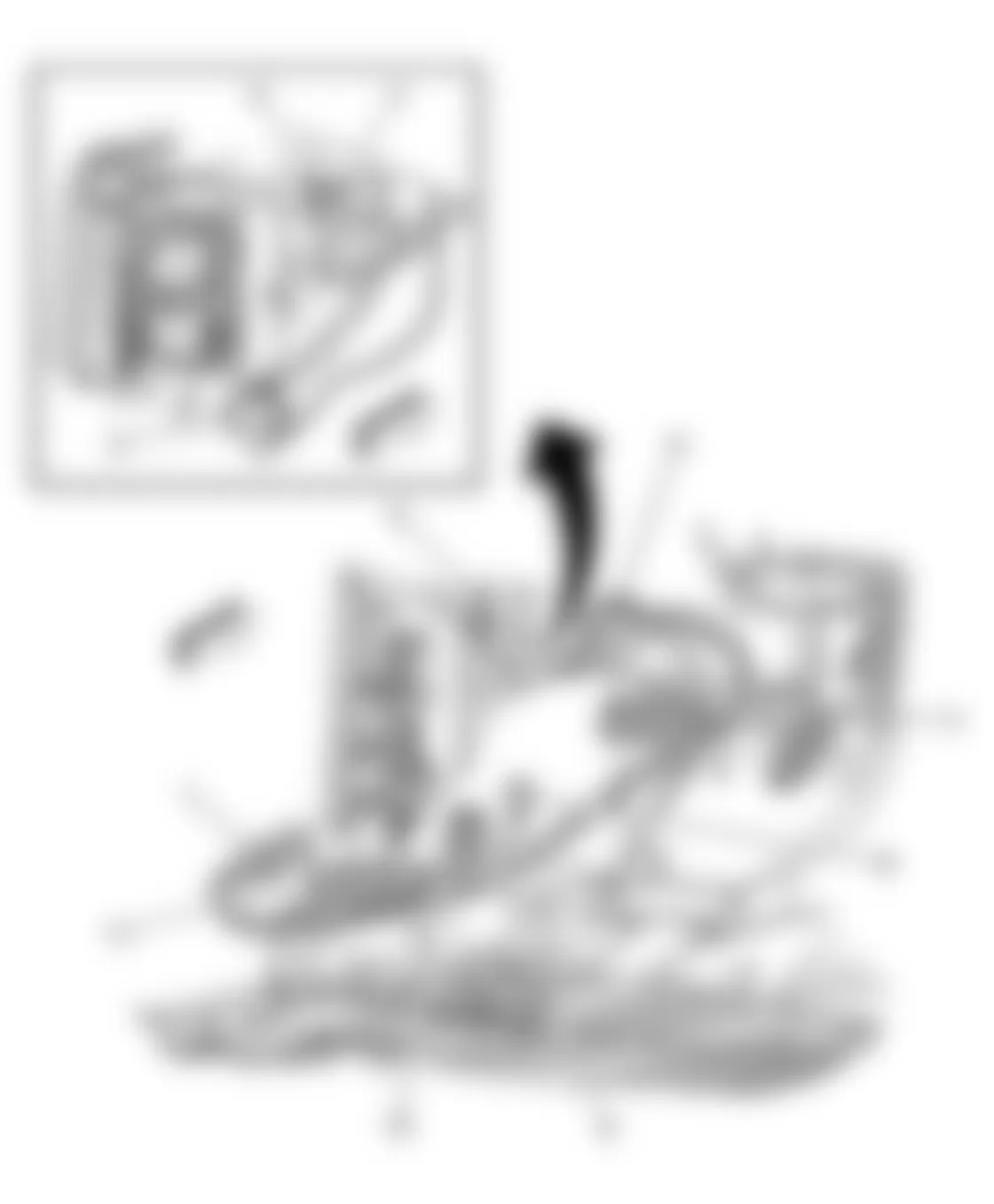
Fig. 1: Chevrolet Cutaway G3500 2004 - Component Locations - Component View - Battery - G106
Callout Component Name 1 Battery Cable (+) 2 Battery 3 G106 4 Battery Cable (-)
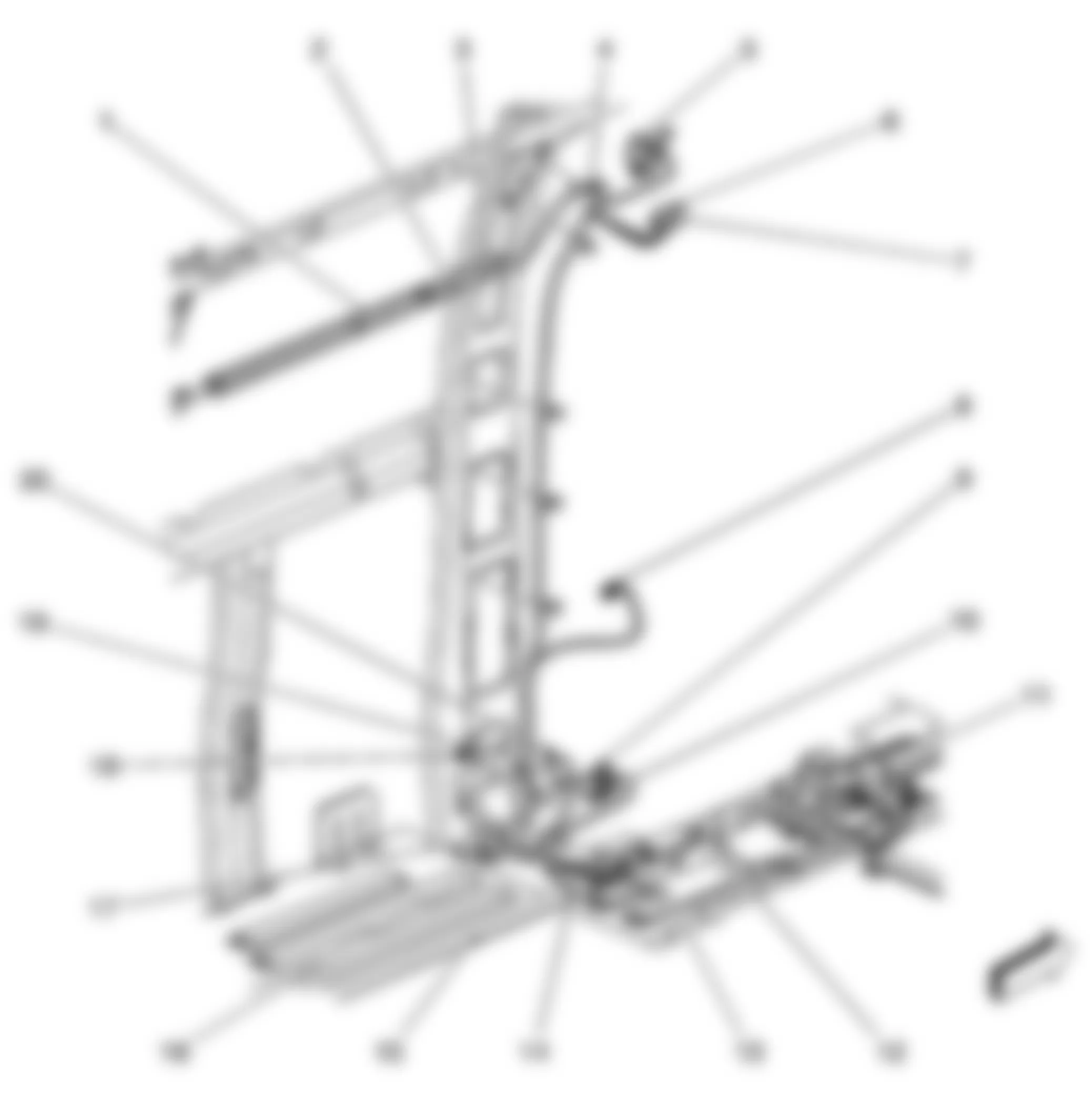
Fig. 2: Chevrolet Cutaway G3500 2004 - Component Locations - Component View - Fuse Block - Underhood
Callout Component Name 1 Fuse Block Underhood - C7 2 Fuse Block Underhood - C5 3 Fuse Block Underhood - C6 4 Fuse Block - Underhood 5 Fuse Block Underhood - C4 6 Fuse Block Underhood - C1 7 Fuse Block Underhood - C2 8 Fuse Block Underhood - C10 9 Fuse Block Underhood - C3 10 Fuse Block Underhood - C8 (UY7) 11 Fuse Block Underhood - C9
Fig. 3: Chevrolet Cutaway G3500 2004 - Component Locations - Component View - Fuse Block - Body
Callout Component Name 1 Fuse Block Body - Cover 2 Fuse Block Body - C4 (YF7) 3 Fuse Block Body - C3 4 Fuse Block Body - C1 5 Inflatable Restraint Sensing and Diagnostic Module (SDM) 6 Fuse Block Body - C2 7 Fuse Block Body - C5 (YF7)

Callout Component Name 1 Marker Lamp Connector - LF 2 G100 3 Headlamp - Low Beam Connector - Left (Composite) 4 Headlamp - High Beam Connector - Left (Composite) 5 S110 6 S118 7 Park/Turn Signal Lamp Connector - RF 8 Marker Lamp Connector - RF 9 G101 10 Headlamp - Low Beam Connector - Right (Composite) 11 Headlamp - High Beam Connector - Right (Composite) 12 Park/Turn Signal Lamp Connector - LF 13 Fuse Block Underhood - C4
Fig. 5: Chevrolet Cutaway G3500 2004 - Component Locations - Component View - G104 & G105
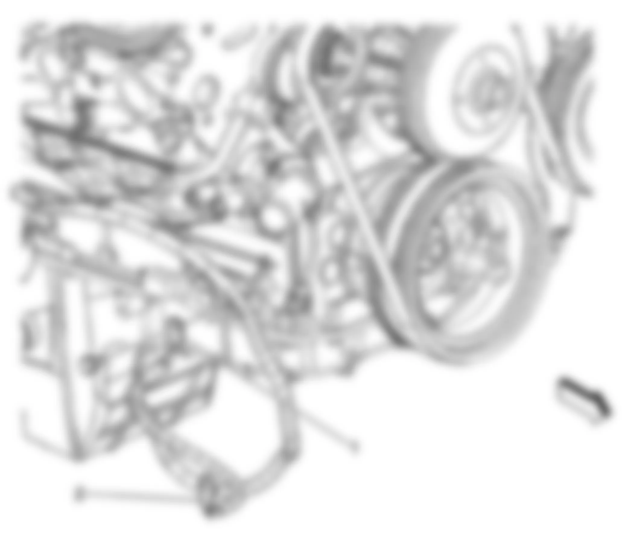
Callout Component Name 1 G104 2 G105

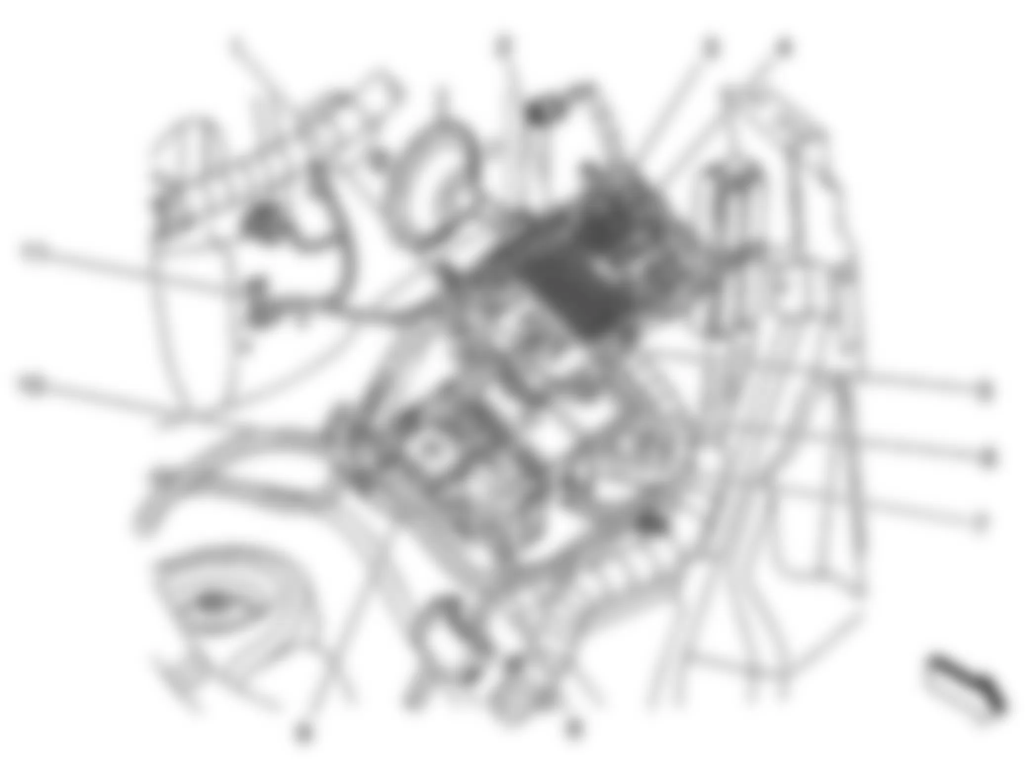
Callout Component Name 1 G102 2 Camshaft Position (CMP) Sensor Connector 3 G103 4 Engine Oil Pressure (EOP) Sensor Connector 5 Knock Sensor (KS) Connector 6 Heated Oxygen Sensor (HO2S) Bank 1 Sensor 1 Connector
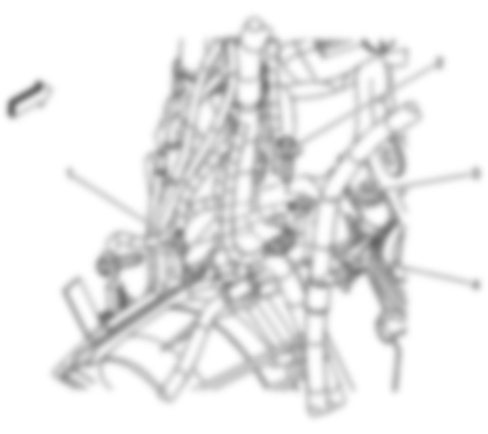
Callout Component Name 1 G102 2 Engine Oil Pressure (EOP) Sensor Connector 3 G103 4 Camshaft Position (CMP) Sensor Connector

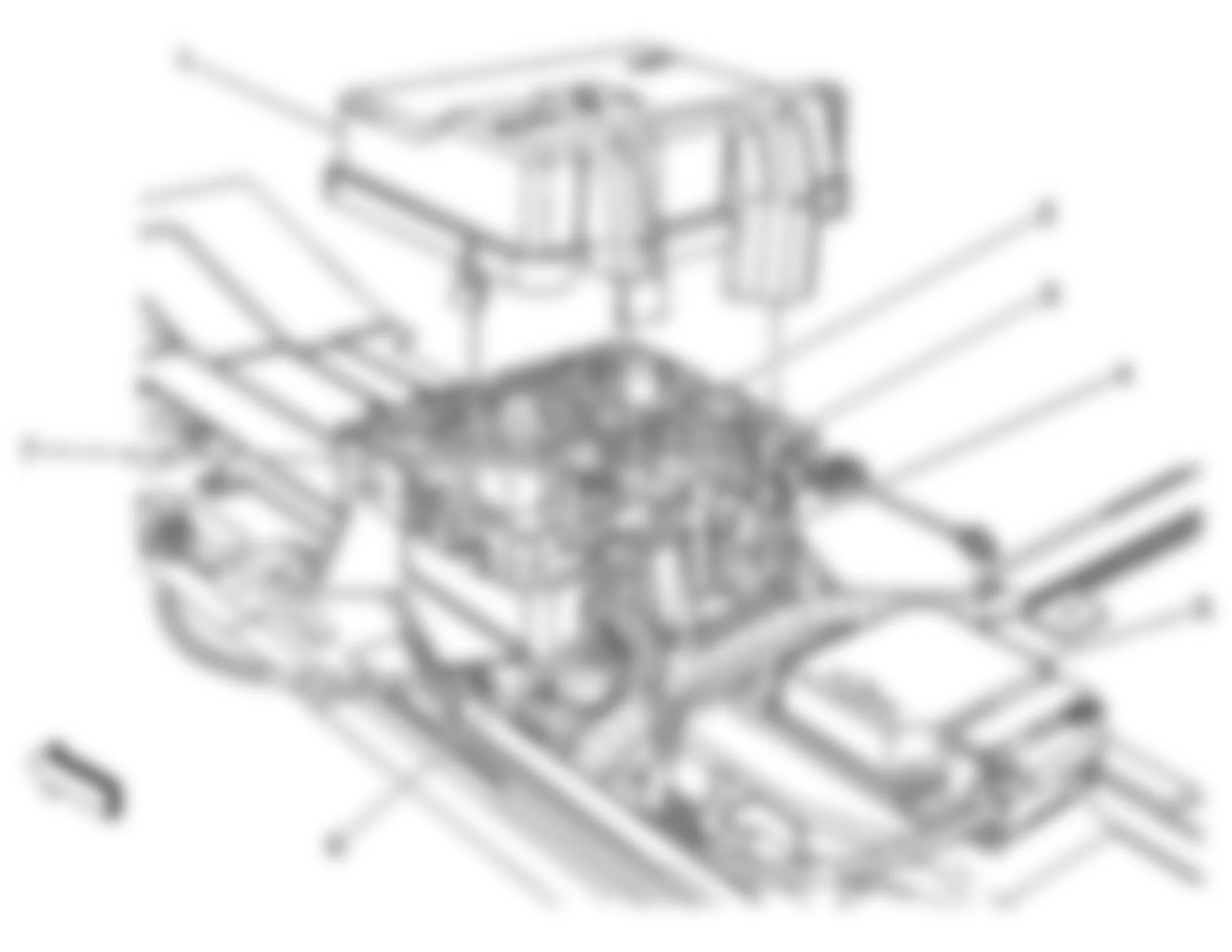
Callout Component Name 1 Fuse Block Underhood - C3 2 Fuse Block Underhood - C7 3 Fuse Block Underhood - C8 (UY7) 4 Wheel Speed Sensor (WSS) Connector - RF 5 Brake Pressure Differential Switch Connector (Light Duty) 6 Evaporative Emission (EVAP) Canister Vent Solenoid Connector (Gas) 7 S301 8 Electronic Brake Control Module (EBCM) Connector (JL4)/Electronic Brake Control Module (EBCM) - C2 (w/o JL4) 9 Electronic Brake Control Module (EBCM) - C1 (w/o JL4) 10 Trailer Right Stop/Turn Relay (UY7) 11 Trailer Left Stop/Turn Relay (UY7) 12 S315 (JL4) 13 G300 14 Wheel Speed Sensor (WSS) Connector - LF 15 C101

Callout Component Name 1 G300 2 Evaporative Emission (EVAP) Canister Vent Solenoid Connector (Gas) 3 Electronic Brake Control Module (EBCM) - C1 4 Electronic Brake Control Module (EBCM) - C2
Callout Component Name 1 Inflatable Restraint Sensing and Diagnostic Module (SDM) Connector 2 C318 3 G301 4 G302 5 G303 6 SP200 7 C222 (YF7) 8 Seat Belt Pretentioner Connector - LF (Light Duty) 9 C300 (Light Duty) 10 Fuse Block Body - C5 (YF7) 11 Fuse Block Body - C3
Fig. 11: Chevrolet Cutaway G3500 2004 - Component Locations - Component View - Upper Steering Column

Callout Component Name 1 Passlock Sensor 2 Ignition Key Alarm Switch 3 Ignition Lock Cylinder Control Actuator 4 Ignition Switch 5 Ignition Key Cylinder 6 Horn Switch 7 Inflatable Restraint Steering Wheel Module 8 Turn Signal/Multifunction Switch 9 Hazard Switch

Callout Component Name 1 C201 (UE1) 2 C225 (DF5/UE1) 3 C312 4 G304 5 C202 (UE1)
Callout Component Name 1 Body Harness Cover 2 S311 (w/o YF7) 3 S310 (w/o YF7) 4 S308 (w/o YF7) 5 C304 (w/o YF7) 6 C203 (YF7/DH6) 7 C303 (YF7/C69 w/Rear Auxiliary Controls) 8 Door Contact Plate Connector - Left Side (E26/AU3) 9 C407 (ENC) 10 C409 (ENC) 11 Fuse Block Body - C2 12 S310 (YF7) 13 S308 (YF7) 14 S311 (YF7) 15 Body Harness 16 Body Harness 17 Lower B-Pillar 18 Door Jamb Switch Connector - LR Side (E26) 19 SP347 20 G347

Callout Component Name 1 G401 2 S451 3 C415 4 C419 5 S450 6 S401 7 S404 8 G402 9 C401 10 C411 11 C407 - 135 Wheel Base (C36/C69) 12 C409 - 135 Wheel Base (C36/C69) 13 C400 14 C412 15 C402 16 S403 (w/o YF7)

Callout Component Name 1 Dome Fluorescent Work Lamp - LR (UF2) 2 Dome Fluorescent Work Lamp - LF (UF2) 3 S350 (UF2) 4 S348 (UF2) 5 Dome Fluorescent Work Lamp - 2 (UF2) 6 Dome Fluorescent Work Lamp - 1 (UF2) 7 Dome Fluorescent Work Lamp - RH (UF2) 8 Access Panel Actuator - Right Side Front 9 Access Panel Actuator - Right Side Rear 10 S409 11 Pro Wiring Harness 12 Body Control Module (BCM) 13 Fuse Block - Body 14 S302 (UF2) 15 S303 16 Dome Fluorescent Work Lamps Relay (UF2) 17 Fuse Block - Rear 18 S309 19 S300 20 S408 21 G403 22 Access Panel Actuator - Left Rear Side Rear 23 Access Panel Actuator - Left Rear Side Front 24 Access Panel Actuator - Left Front Side Rear 25 Access Panel Actuator - Left Front Side Front
Fig. 16: Chevrolet Cutaway G3500 2004 - Component Locations - Component View - Rear Frame

Callout Component Name 1 C405 (Cutaway) 2 S402 3 G400
Chevrolet Cutaway G3500 2004 - Electrical Center Identification Views Fuse Block - Underhood Label

Chevrolet Cutaway G3500 2004 Fuse Block - Underhood - Label Usage
No. Fuse/Circuit Breaker Rating Description 1 RADIO BAT Fuse 15A Vehicle Communication Interface Module (VCIM) and Radio (w/o UL5) or Chime Module (UL5) 2 PCM BAT Fuse 20A Powertrain Control Module (PCM) 3 LR STOP/TRN Fuse 10A Trailer Stop/Turn Relay - Left 4 RR STOP/TRN Fuse 10A Trailer Stop/Turn Relay - Right 5 TRLR BU Fuse 10A Trailer Wiring Harness (UY7) or C405 (Cutaway) 6 IGN 0 Fuse 10A Powertrain Control Module (PCM) and Automatic Transmission 7 STOP LP Fuse 15A Stop Lamp Switch 8 RR DEF/HTD MIR Fuse 20A HVAC Control Assembly 9 RT DRL/TRN Fuse 10A Park/Turn Signal Lamp - RF 10 LT DRL/TRN Fuse 10A Park/Turn Signal Lamp - LF 11 TBC 4 Fuse 15A Body Control Module (BCM) 12 FUEL PUMP Fuse 20A FUEL PUMP Relay 13 TRLR Fuse 30A Trailer Wiring Harness 14 FLASHER Fuse 15A Turn Signal Hazard Flasher Module 15 HORN Fuse 15A HORN Relay 16 TBC 3 Fuse 15A Body Control Module (BCM) 17 TRL STOP/TRN Fuse 15A Trailer Stop/Turn Relay - Left and Trailer Stop/Turn Relay - Right 18 TBC 2 Fuse 15A Body Control Module (BCM) 19 TBC Fuse 10A Body Control Module (BCM) 20 RFA Fuse 10A Remote Control Door Lock Receiver (RCDLR) 21 ENG 2 Fuse 10A Even Fuel Injectors and Even Ignition Coils (4.8L/5.3L/6.0L) or Even Fuel Injectors and Ignition Coil (4.3L) 22 IGN E Fuse 10A Stop Lamp Switch and A/C Relay 23 ENG 1 Fuse 15A Odd Fuel Injectors, Odd Ignition Coils, EVAP Canister Purge Solenoid, MAF Sensor, PNP Switch (4.8L/5.3L/6.0L) or Odd Fuel Injectors, Ignition Control Module, EVAP Canister Purge Solenoid, MAF Sensor, PNP Switch (4.3L) 24 TBC IGN 1 Fuse 10A Body Control Module (BCM) 25 SPARE Fuse - Not Used 26 ISRV Fuse 10A Inside Rearview Mirror 27 CRANK Fuse 10A Powertrain Control Module (PCM) 28 BTSI Fuse 10A Stop Lamp Switch 29 AUX PWR Fuse 20A Auxiliary Power Outlet 30 CIGAR Fuse 15A Cigar Lighter and Data Link Connector (DLC) 31 IPC Fuse 10A Instrument Panel Cluster (IPC) 32 A/C Fuse 10A A/C Relay 33 SPARE Fuse - Not Used 34 CAN VENT Fuse 10A EVAP Canister Vent Solenoid and SPARE Relay 35 SPARE Fuse - Not Used 36 BTSI/BU Fuse 15A Park/Neutral Position (PNP) Switch 37 SIR Fuse 10A Inflatable Restraint I/P Module Disable Switch and SDM 38 PCM IGN 1 Fuse 15A Powertrain Control Module (PCM) and Cruise Control Module (CCM) - w/o JL4 or Throttle Actuator Control (TAC) Module - JL4 39 O2B Fuse 15A HO2S Bank 1 Sensor 2 and Bank 2 Sensor 2 40 O2A Fuse 15A HO2S Bank 1 Sensor 1 and Bank 2 Sensor 1 41 WPR Fuse 15A WPR Relay 42 RH-LOBM Fuse 10A Headlamp Low Beam Right (Composite) or Headlamp - Right (Sealed) 43 LH-LOBM Fuse 10A Headlamp Low Beam Left (Composite) or Headlamp - Left (Sealed) 44 LH-HIBM Fuse 10A Headlamp High Beam Left (Composite) or Headlamp - Left (Sealed) 45 RH-HIBM Fuse 10A Headlamp High Beam Right (Composite) or Headlamp - Right (Sealed) 46 TBC ACC Fuse 10A Body Control Module (BCM) 47 FR WPR Fuse 25A Windshield Wiper Motor 48 ABS Fuse 60A Electronic Brake Control Module (EBCM) 49 IGN A Fuse 40A STARTER Relay and Ignition Switch 50 TRLR Fuse 30A Trailer Wiring Harness 51 BLOW Fuse 40A Blower Motor Resistor Assembly 52 IGN B Fuse 40A Ignition Switch 53 WPR Relay - Windshield Wiper Motor 54 A/C Relay - A/C Compressor Clutch 55 SPARE Relay - Not Used 56 HDLP-HIBM Relay - RH-HIBM Fuse and LH-HIBM Fuse 57 FUEL PUMP Relay - Fuel Pump 58 HDLP-LOBM Relay - RH-LOBM Fuse and LH-LHBM Fuse 59 HORN Relay - Horn Assembly 60 PWR SEAT Circuit Breaker 30A Seat Adjuster Switch - Driver and Seat Adjuster Switch - Front Passenger 61 STARTER Relay - Starter 62 SPARE Relay - Not Used 63 SPARE Fuse - Not Used 64 SPARE Fuse - Not Used 65 MEGA Fuse 125A Fuse Block - Body
Chevrolet Cutaway G3500 2004 - Fuse Block - Underhood Top View
Fig. 18: Chevrolet Cutaway G3500 2004 - Component Locations - Fuse Block - Underhood Top View

Chevrolet Cutaway G3500 2004 - Fuse Block - Underhood Bottom View
Fig. 19: Chevrolet Cutaway G3500 2004 - Component Locations - Fuse Block - Underhood Bottom View

Chevrolet Cutaway G3500 2004 Fuse Block - Underhood - C1 Connector Identification
Connector Part Information
Pin Wire Color Circuit No. Function A1 - - Not Used A2 YE/BK 625 Starter Enable Relay Control A3-A7 - - Not Used A8 PU 420 TCC Brake Switch/Cruise Control Release Signal A9 L-GN 275 Park Neutral Position Switch Park Signal A10 RD/WH 440 Battery Positive Voltage (Late Production) RD/WH 440 Battery Positive Voltage (Late Production) OG 440 Battery Positive Voltage (Early Production) OG 440 Battery Positive Voltage (Early Production) A11-A12 - - Not Used B1 - - Not Used B2 D-GN 1433 Neutral Safety Back Up Switch Signal B3 - - Not Used B4 PK 139 Ignition 1 Voltage PK 139 Ignition 1 Voltage (4.8L/5.3L/6.0L) B5-B9 - - Not Used B10 PU 806 Crank Voltage B11-B12 - - Not Used C1 PU 6 Starter Solenoid Crank Voltage C2 BK 1250 Ground C3 PK 339 Ignition 1 Voltage C4 PK 139 Ignition 1 Voltage PK 139 Ignition 1 Voltage C5-C9 - - Not Used C10 PK 239 Ignition 1 Voltage C11-C12 - - Not Used D1-D3 - - Not Used D4 PK 139 Ignition 1 Voltage PK 139 Ignition 1 Voltage D5-D9 - - Not Used D10 PK 239 Ignition 1 Voltage PK 239 Ignition 1 Voltage (4.8L/5.3L/6.0L) D11 - - Not Used D12 D-GN/WH 459 A/C Compressor Clutch Relay Control (C60) E1 PK 539 Ignition 1 Voltage PK 539 Ignition 1 Voltage E2 PK 439 Ignition 1 Voltage E3 - - Not Used E4 PK 139 Ignition 1 Voltage PK 139 Ignition 1 Voltage E5 - - Not Used E6 RD/WH 140 Battery Positive Voltage (Late Production) OG 140 Battery Positive Voltage (Early Production) E7-E9 - - Not Used E10 PK 239 Ignition 1 Voltage PK 239 Ignition 1 Voltage E11-E12 - - Not Used F1 PK 1539 Ignition 1 Voltage PK 1539 Ignition 1 Voltage F2 - - Not Used F3 PK 1020 Ignition 0 Voltage PK 1020 Ignition 0 Voltage F4 D-GN 1329 Horn Fuse Supply Voltage F5-F7 - - Not Used F8 D-GN/WH 465 Fuel Pump Relay Control - Primary F9-F10 - - Not Used F11 D-GN 1324 Backup Lamp Supply Voltage (Late Production) L-GN 1324 Backup Lamp Supply Voltage (Early Production) F12 D-GN 59 A/C Compressor Clutch Supply Voltage (C60)

Chevrolet Cutaway G3500 2004 Fuse Block - Underhood - C2 Connector Identification
Connector Part Information
Pin Wire Color Circuit No. Function A1 L-GN/BK 584 A/T Shift Lock Control Switch Supply Voltage A2 WH 1390 Accy/Run/Start Voltage A3 YE 5 Crank Voltage A4 RD/WH 4440 Battery Positive Voltage (C49/DE5/DE7) A5 - - Not Used A6 RD/WH 540 Battery Positive Voltage A7 PK 1439 Ignition 1 Voltage (DF5) A8 - - Not Used A9 BN 441 Ignition 3 Voltage A10 OG 4040 Battery Positive Voltage A11 YE 343 Accessory Voltage A12 - - Not Used B1 PK/WH 1970 Headlamp Low Beam Relay Control B2 - - Not Used B3 RD/WH 1140 Battery Positive Voltage B4 D-BU 47 Trailer Auxiliary Supply Voltage (UY7) B5 RD/WH 3540 Battery Positive Voltage B6 BN 2109 Trailer Park Lamps Supply Voltage (Cutaway/UY7) B7 RD/WH 2940 Battery Positive Voltage (UY7) B8 PK 39 Ignition 1 Voltage B9 - - Not Used B10 RD/WH 340 Battery Positive Voltage (UE1) B11 WH 17 Stop Lamp Switch Signal (Cutaway) B12 - - Not Used C1 D-GN 5365 Right DRL/Turn Supply Voltage C2 RD/WH 2240 Battery Positive Voltage C3 TN 28 Horn Relay Control TN 28 Horn Relay Control C4-C7 - - Not Used C8 D-GN/WH 636 Ambient Air Temperature Sensor Signal (DF5) C9 - - Not Used C10 YE 143 Accessory Voltage C11 - - Not Used C12 PK 739 Ignition 1 Voltage D1 RD/WH 2140 Battery Positive Voltage D2 - - Not Used D3 PK 439 Ignition 1 Voltage (K34 w/o JL4) PK 1339 Ignition 1 Voltage (JL4) BN 341 Ignition 1 Voltage (JL4) D4 PK 1139 Ignition 1 Voltage (Heavy Duty) D5 TN/WH 1969 Headlamp High Beam Relay Control D6-D7 - - Not Used D8 D-GN 19 Right Rear Stop/Turn Lamp Supply Voltage (Cutaway/UY7) D9 - - Not Used D10 RD/WH 340 Battery Positive Voltage D11 D-BU/WH 149 Courtesy Lamp Supply Voltage (Cutaway) D12 - - Not Used E1 D-BU 5364 Left DRL/Turn Supply Voltage E2 RD/WH 1040 Battery Positive Voltage E3 PK 3 Ignition 1 Voltage E4 PK 1139 Ignition 1 Voltage E5 BN 4 Accessory Voltage E6 OG 228 Windshield Washer Pump Control E7 - - Not Used E8 PU 420 TCC Brake Switch/Cruise Control Release Signal (K34 w/o JL4) E9 PU 420 TCC Brake Switch/Cruise Control Release Signal E10 RD/WH 2340 Battery Positive Voltage E11 YE/BK 1334 Left Rear Turn Signal Lamp Supply Voltage (Cutaway) E12 PK 739 Ignition 1 Voltage PK 739 Ignition 1 Voltage F1 RD/WH 1240 Battery Positive Voltage (AU0) F2 RD/WH 640 Battery Positive Voltage RD/WH 640 Battery Positive Voltage F3 BN 2309 Front Park Lamps Supply Voltage F4 PK 1020 Ignition 0 Voltage F5 OG 2268 Windshield Washer Relay Control F6 - - Not Used F7 TN/WH 1704 Low Reference (DF5) F8 - - Not Used F9 YE 18 Left Rear Stop/Turn Lamp Supply Voltage (Cutaway/UY7) F10 RD/WH 1540 Battery Positive Voltage F11 D-GN/WH 1335 Right Rear Turn Signal Lamp Supply Voltage (Cutaway) F12 - - Not Used

Chevrolet Cutaway G3500 2004 Fuse Block - Underhood - C3 Connector Identification
Connector Part Information
Pin Wire Color Circuit No. Function A1-A6 - - Not Used B1 L-GN 1624 Trailer Backup Lamps Supply Voltage (Cutaway/UY7) B2 OG 1340 Battery Positive Voltage (UY7) OG 1340 Battery Positive Voltage (UY7) B3-B5 - - Not Used B6 D-GN/WH 1335 Right Rear Turn Signal Lamp Supply Voltage (Cutaway) C1 D-GN 619 Right Rear Turn Signal Lamp Supply Voltage (Cutaway/UY7) C2 D-BU 47 Trailer Auxiliary Supply Voltage (UY7) C3-C4 - - Not Used C5 GY 120 Fuel Pump Supply Voltage C6 YE/BK 1334 Left Rear Turn Signal Lamp Supply Voltage (Cutaway) D1 BN 2109 Trailer Park Lamps Supply Voltage (Cutaway/UY7) D2 YE 618 Left Rear Turn Signal Lamp Supply Voltage (Cutaway/UY7) D3-D6 - - Not Used E1 BN 441 Ignition 3 Voltage E2-E4 - - Not Used E5 D-BU/WH 149 Courtesy Lamp Supply Voltage (Cutaway) E6 - - Not Used F1 PU 420 TCC Brake Switch/Cruise Control Release Signal F2 - - Not Used F3 WH 17 Stop Lamp Switch Signal (Cutaway) F4-F6 - - Not Used

Chevrolet Cutaway G3500 2004 Fuse Block - Underhood - C4 Connector Identification
Connector Part Information
Pin Wire Color Circuit No. Function A TN/WH 1704 Low Reference (DF5) B D-GN/WH 636 Ambient Air Temperature Sensor Signal (DF5) C-D - - Not Used E YE 712 Left Headlamp Low Beam Supply Voltage F TN/WH 312 Right Headlamp Low Beam Supply Voltage G-H - - Not Used J BN 2309 Front Park Lamps Supply Voltage K BN 2309 Front Park Lamps Supply Voltage L BN 2309 Front Park Lamps Supply Voltage M BN 2309 Front Park Lamps Supply Voltage N L-BU 2114 Left Front Turn Signal Lamps Supply Voltage P D-BU 2115 Right Front Turn Signal Lamps Supply Voltage R L-GN/BK 311 Right Headlamp High Beam Supply Voltage S D-GN/WH 711 Left Headlamp High Beam Supply Voltage

Chevrolet Cutaway G3500 2004 Fuse Block - Underhood - C5 Connector Identification
Connector Part Information
Pin Wire Color Circuit No. Function A RD/BK 342 Battery Positive Voltage B RD/BK 142 Battery Positive Voltage

Chevrolet Cutaway G3500 2004 Fuse Block - Underhood - C6 Connector Identification
Connector Part Information
Pin Wire Color Circuit No. Function A - - Not Used B RD/BK 542 Battery Positive Voltage (Late Production) RD 542 Battery Positive Voltage (Early Production)

Chevrolet Cutaway G3500 2004 Fuse Block - Underhood - C7 Connector Identification
Connector Part Information
Pin Wire Color Circuit No. Function A RD/BK 642 Battery Positive Voltage (Late Production w/o JL4) RD 442 Battery Positive Voltage (JL4) RD 642 Battery Positive Voltage (Early Production) B - - Not Used

Chevrolet Cutaway G3500 2004 - Fuse Block - Body Label

Chevrolet Cutaway G3500 2004 Fuse Block - Body - Label Usage
No. Fuse/Circuit Breaker Rating Description 1 SPARE Fuse - Not Used 2 OSRVM Fuse 10A Outside Rearview Mirror Switch 3 CTSY LP/SEO Fuse 15A CTSY LP Relay (YF7) 4 LR STOP/TRN Fuse 10A Tail Lamp Assembly - Left 5 CARGO LKS Fuse 10A CARGO UNLK Relay 6 RR STOP/TRN Fuse 10A Tail Lamp Assembly - Right 7 DRV LKS Fuse 10A DRV UNLK Relay 8 STOP/CHMSL Fuse 10A Center High Mounted Stop Lamp (CHMSL) and Cruise Control Module (CCM) 9 HVAC 1 Fuse 10A HVAC Control Assembly and Air Temperature Actuator 10 HVAC Fuse 20A HVAC Control Assembly 11 BRKS Fuse 10A Electronic Brake Control Module (EBCM) 12 HTD MIR/DEFOG Fuse 30A RR DEFOG Relay 13 RR BLOWER Fuse 30A Low/Med/High Speed Blower Motor Relays - Auxiliary 14 DR TRN MIR Fuse 10A Outside Rearview Mirror - Driver 15 DOOR LKS Fuse 20A DOOR LKS Relay 16 UPFTR PRK Fuse 10A C320 - Upfitter Wiring Harness 17 NOT AVAILABLE - Not Used 18 LR PRK Fuse 10A Tail Lamp Assembly - Left and License Lamp 19 PASS TRN MIR Fuse 10A Outside Rearview Mirror - Passenger 20 RR PRK Fuse 10A Tail Lamp Assembly - Right 21 TRLR PRK Fuse 15A Trailer Wiring Harness - (UY7) or C405 (Cutaway) 22 FR PRK Fuse 10A Inflatable Restraint I/P Module Disable Switch, Park/Turn signal Lamps - LF/RF and Marker Lamps - LF/RF 23 WND RAP Relay - PWR WND Circuit Breaker 24 AUXILIARY Relay - Upfitter wiring Harness - C321 25 RR DEFOG Relay - Rear Window Defogger Grid - Left/Right 26 CTSY LP Relay - Courtesy/Reading Lamps, C320 (YF7), C405 (Cutaway), Dome Lamp (Cargo) 27 CARGO UNLK Relay - Mini Wedge (Door Jamb Switch) - Cargo 28 DRV UNLK Relay - Mini Wedge (Door Jamb Switch) - Driver 29 PARK LP Relay - FR PRK, LR PRK, RR PRK, TRLR PRK and UPFTR PRK Fuses 30 DOOR LKS Relay - Mini Wedge (Door Jamb Switch) - Driver/Front Passenger/Cargo and Door Lock Actuators - LR/RR 31 PASS UNLK Relay - Mini Wedge (Door Jamb Switch) - Front Passenger and Door Lock Actuators - LR/RR 32 AUXILIARY 1 Fuse 50A Upfitter Wiring Harness - C222, C321 20A Cooling Fan (SEO) 33 AUXILIARY 2 Fuse 50A AUXILIARY Relay (YF7) 20A AUXILIARY Relay (SEO) 34 PWR WND Circuit Breaker 25A Window Switch - Driver/Front Passenger
Chevrolet Cutaway G3500 2004 - Fuse Block - Body Top View
Fig. 21: Chevrolet Cutaway G3500 2004 - Component Locations - Fuse Block - Body Top View
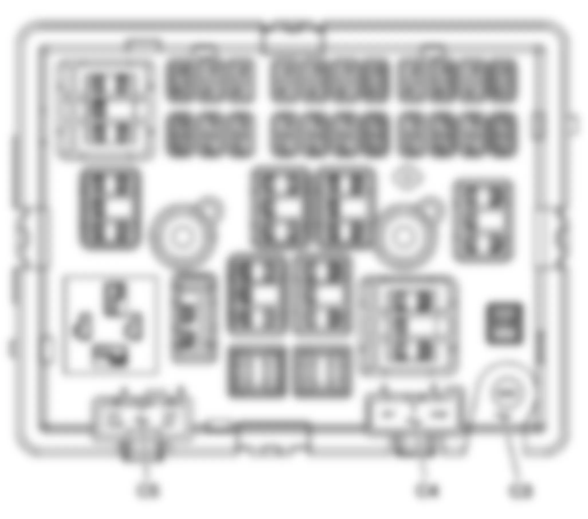
Chevrolet Cutaway G3500 2004 - Fuse Block - Body Bottom View
Fig. 22: Chevrolet Cutaway G3500 2004 - Component Locations - Fuse Block - Body Bottom View

Chevrolet Cutaway G3500 2004 Fuse Block - Body - C1 Connector Identification
Connector Part Information
Pin Wire Color Circuit No. Function A1 BN 2109 Trailer Park Lamps Supply Voltage (Cutaway/UY7) A2-A3 - - Not Used A4 L-GN 1391 Driver Door Unlock Relay Control (AU3) A5 D-BU/WH 149 Courtesy Lamp Supply Voltage (w/o YF7) D-BU/WH 149 Courtesy Lamp Supply Voltage (Cutaway) A6-A10 - - Not Used A11 D-BU 245 Passenger Door Lock Switch Unlock Control Voltage (AU3) A12 RD/WH 3540 Battery Positive Voltage B1 D-GN 19 Right Rear Stop/Turn Lamp Supply Voltage (Passenger/Cargo) D-GN 19 Right Rear Stop/Turn Lamp Supply Voltage (UY7) B2-B3 - - Not Used B4 WH 17 Stop Lamp Switch Signal (Passenger/Cargo) WH 17 Stop Lamp Switch Signal (Passenger/Cargo) B5-B6 - - Not Used B7 L-BU 1344 Cargo Door Release Relay Control (AU3) B8 D-BU/WH 1315 Right Front Turn Signal Lamp Supply Voltage B9-B11 - - Not Used B12 WH 193 Rear Defog Relay Control (C49/DE5/DE7) C1-C3 - - Not Used C4 BN 141 Ignition 3 Voltage C5-C7 - - Not Used C8 L-BU 244 Passenger Door Lock Switch Lock Control Voltage (AU3) C9-C11 - - Not Used C12 WH 194 Door Unlock Control (AU3) D1 - - Not Used D2 L-BU 1320 CHMSL Supply Voltage (Passenger/Cargo w/UY7) L-BU 1320 CHMSL Supply Voltage (Passenger/Cargo w/K34) D3 - - Not Used D4 BN 441 Ignition 3 Voltage BN 441 Ignition 3 Voltage (JL4) D5-D8 - - Not Used D9 GY/BK 690 Courtesy Lamp High Control (YF7) D10-D11 - - Not Used D12 BN/WH 230 Instrument Panel Lamps Dimming Control E1 BN 2309 Front Park Lamps Supply Voltage BN 2309 Front Park Lamps Supply Voltage (Heavy Duty) E2 YE 18 Left Rear Stop/Turn Lamp Supply Voltage (Passenger/Cargo) YE 18 Left Rear Stop/Turn Lamp Supply Voltage (UY7) E3 - - Not Used E4 WH 1080 Park Lamp Relay Control E5 - - Not Used E6 D-GN/WH 1335 Right Rear Turn Signal Lamp Supply Voltage (Cutaway) E7 - - Not Used E8 OG 300 Ignition 3 Voltage E9-E11 - - Not Used E12 L-BU 195 Door Lock Control (AU3) F1 TN 755 RAP Relay Coil Control (A31) F2 YE/BK 1334 Left Rear Turn Signal Lamp Supply Voltage (Cutaway) F3 L-BU/WH 1314 Left Front Turn Signal Lamp Supply Voltage F4-F6 - - Not Used F7 BK 350 Ground F8 - - Not Used F9 BN 341 Ignition 3 Voltage (C49/DE5/DE7) F10 BN 341 Ignition 3 Voltage F11-F12 - - Not Used
Chevrolet Cutaway G3500 2004 Fuse Block - Body - C2 Connector Identification
Connector Part Information
Pin Wire Color Circuit No. Function A1 RD/WH 1740 Battery Positive Voltage (C36/C69/ENC) A2 OG 4340 Battery Positive Voltage (DE5/DE7) A3 D-GN/WH 1335 Right Mirror Turn Signal Lamp Supply Voltage (DE7) A4 D-GN 619 Right Rear Turn Signal Lamp Supply Voltage (Passenger/Cargo) A5-A7 - - Not Used A8 WH 193 Rear Defog Relay Supply Voltage (DE5/DE7) WH 193 Rear Defog Relay Supply Voltage (DE5/DE7) A9 - - Not Used A10 TN 294 Door Lock Actuator Unlock Control (AU3) A11 BN/WH 230 Instrument Panel Lamps Dimming Control (AU3/A31) BN/WH 230 Instrument Panel Lamps Dimming Control (AU3/A31) A12 BN/WH 230 Instrument Panel Lamps Dimming Control B1 - - Not Used B2 YE/BK 1334 Left Mirror Turn Signal Lamp Supply Voltage (DE7) B3-B4 - - Not Used B5 TN/BK 1095 Right Rear Door Lock Actuator Unlock Control (AU3) B6 - - Not Used B7 GY 295 Door Lock Actuator Lock Control (AU3) GY 295 Door Lock Actuator Lock Control (AU3) B8 L-BU 195 Door Lock Control (AU3) L-BU 195 Door Lock Control (AU3) B9 - - Not Used B10 TN 294 Door Lock Actuator Unlock Control (AU3 w/E26) B11 BN/WH 230 Instrument Panel Lamps Dimming Control (UK6) B12 BN/WH 230 Instrument Panel Lamps Dimming Control C1 BN 2609 Right Rear Park Lamps Supply Voltage C2-C3 - - Not Used C4 YE 618 Left Rear Turn Signal Lamp Supply Voltage (Passenger/Cargo) C5 GY 295 Door Lock Actuator Lock Control (AU3 w/E26) C6-C7 - - Not Used C8 PU 293 Rear Defog Element Supply Voltage (C49) C9 L-BU 195 Door Lock Control (AU3) C10-C11 - - Not Used C12 WH 194 Door Unlock Control (AU3) WH 194 Door Unlock Control (AU3) D1 BN 2209 Rear Park Lamps Supply Voltage (YF7) D2 BN 341 Ignition 3 Voltage (C69) D3-D4 - - Not Used D5 GY 295 Door Lock Actuator Lock Control (AU3) GY 295 Door Lock Actuator Lock Control (AU3) D6-D7 - - Not Used D8 PU 293 Rear Defog Element Supply Voltage (C49) D9-D11 - - Not Used D12 WH 194 Door Unlock Control (AU3) E1 - - Not Used E2 BN 341 Ignition 3 Voltage (C36/C69/ENC) E3-E6 - - Not Used E7 D-BU/WH 149 Courtesy Lamp Supply Voltage D-BU/WH 149 Courtesy Lamp Supply Voltage (Cargo w/o YF7) E8 TN 694 Driver Door Lock Actuator Unlock Control (AU3) E9 - - Not Used E10 TN 294 Door Lock Actuator Unlock Control (AU3) E11 D-GN 1001 RAP Fuse Supply Voltage (A31) E12 RD/WH 3540 Battery Positive Voltage (AG1/AG2) F1 BN 2509 Left Rear Park Lamps Supply Voltage F2 L-BU 1320 CHMSL Supply Voltage F3-F10 - - Not Used F11 D-GN 1001 RAP Fuse Supply Voltage (A31) F12 RD/WH 3540 Battery Positive Voltage (AG1/AG2)

Chevrolet Cutaway G3500 2004 Fuse Block - Body - C4 (YF7/YF1 Late Production) Connector Identification
Connector Part Information
Pin Wire Color Circuit No. Function A BN 541 Ignition 3 Voltage B RD/BK 1042 Battery Positive Voltage (w/o PRP) RD 1042 Battery Positive Voltage (PRP)
Chevrolet Cutaway G3500 2004 Fuse Block - Body - C5 Connector Identification
Connector Part Information
Pin Wire Color Circuit No. Function A RD 4042 Battery Positive Voltage (JL4) RD/BK 1042 Battery Positive Voltage (YF7) B BN 541 Ignition 3 Voltage (YF7)
Chevrolet Cutaway G3500 2004 - Fuse Block - Rear (PRP) - Top View
Fig. 23: Chevrolet Cutaway G3500 2004 - Component Locations - Fuse Block - Rear (PRP) - Top View

Chevrolet Cutaway G3500 2004 Fuse Block - Rear (PRP) - Fuse Applications
No. Fuse/Circuit Breaker Rating Description 1 Access Panel Relay - Left Side Rear - Access Panel Latches - Left Side Rear 2 Dome Fluorescent Work Lamps Fuse 10 Dome Fluorescent Work Lamps (UF2) 3 Panel Actuator Fuse 15 Access Panel Relays 4 - - Not Used 5 Access Panel Relay - Left Side Front - Access Panel Latches - Left Side Front 6 Access Panel Relay - Right Side - Access Panel Latches - Right Side
Chevrolet Cutaway G3500 2004 - Fuse Block - Rear (PRP) - Bottom View
Fig. 24: Chevrolet Cutaway G3500 2004 - Component Locations - Fuse Block - Rear (PRP) - Bottom View

Chevrolet Cutaway G3500 2004 Fuse Block - Rear (PRP) Wire Entry
Connector Part Information
Pin Wire Color Circuit No. Function 1 OG 740 Battery Positive Voltage 2 TN 294 Access Panel Left Front Side Lock Actuators Unlock Control 3 L-BU 195 Access Panel Left Side Front Relay Control 4 - - Not Used 5 OG 740 Battery Positive Voltage 6 OG 740 Battery Positive Voltage 7 PK 1092 Access Panel Left Rear Side Lock Actuators Unlock Control 8 L-GN 1391 Access Panel Left Side Rear Relay Control 9 - - Not Used 10 OG 740 Battery Positive Voltage 11 OG 740 Battery Positive Voltage 12 TN/BK 1095 Access Panel Right Side Lock Actuators Unlock Control 13 L-BU 1344 Access Panel Right Side Relay Control 14 - - Not Used 15 OG 740 Battery Positive Voltage 16 RD 1042 Battery Positive Voltage (UF2) 17 OG 840 Battery Positive Voltage (UF2) 18 RD 1042 Battery Positive Voltage 19 OG 740 Battery Positive Voltage 20-21 - - Not Used