
Chevrolet Lumina APV 1994 - G - TESTS W/CODES - 3.1L 1994 ENGINE PERFORMANCE General Motors Corp. Self-Diagnostics - 3.1L V6
Chevrolet Lumina APV 1994 - INTRODUCTION
Most engine control problems result from mechanical failures, poor electrical connections or damaged vacuum hoses. Before condemning the computer system, perform checks and inspections covered in BASIC TESTING article in this section. Failure to do so may result in lost diagnostic time.
If no faults were found while performing BASIC TESTING PROCEDURES, proceed with DIAGNOSTIC PROCEDURE. If no fault codes or only a non-running Code 12 is present and driveability problems exist, proceed to TESTS W/O CODES article in this section for diagnosis by symptom (i.e., ROUGH IDLE, NO START, etc.). If only intermittent codes are present, see INTERMITTENTS in TESTS W/O CODES article in this section.
Chevrolet Lumina APV 1994 - TERMINOLOGY
Due to Federal government requirements, manufacturers may use names and acronyms for systems and components different than those used in previous years. The following table will help eliminate confusion when dealing with these components and systems. Only relevant components and systems whose names have changed from current General Motors Corp. terminology have been listed.
Chevrolet Lumina APV 1994 SAE TERMINOLOGY
Former Name Or Acronym New Name Or Acronym ALDL Data Link Connector (DLC) CHECK ENGINE Light Malfunction Indicator Light (MIL) CTS Engine Coolant Temperature Sensor Diagnostic Circuit Check On-Board Diagnostic (OBD) System Check ESC System Knock Sensor (KS) System EST System Ignition Control (IC) System MAT Sensor Intake Air Temperature (IAT) Sensor Park/Neutral (P/N) Switch Park/Neutral Position (PNP) Switch Port Fuel Injection Multiport Fuel Injection Scan Data Scan Tester (ST) Data SERVICE ENGINE SOON Light Malfunction Indicator Light (MIL) Thermostatic Air Cleaner (TAC) Air Cleaner (ACL) Throttle Position Sensor (TPS) Throttle Position (TP) Sensor Throttle Position Switch Closed Throttle Position (CTP) Switch Throttle Position Switch Wide Open Throttle (WOT) Switch Viscous Converter Clutch (VCC) Torque Converter Clutch (TCC)
Chevrolet Lumina APV 1994 - SELF-DIAGNOSTIC SYSTEM DESCRIPTION
All vehicle are equipped with either an Electronic Control Module (ECM), Powertrain Control Module (PCM) or Vehicle Control Module (VCM). Unless specifically stated, references to ECM also apply to PCM or VCM equipped vehicles.
The ECM is equipped with a self-diagnostic system, which detects system failures or abnormalities. When a malfunction occurs, ECM will illuminate the SERVICE ENGINE SOON light located on instrument panel. This light is also referred to as the Malfunction Indicator Light (MIL). When malfunction is detected and MIL is turned on, a corresponding trouble code will be stored in ECM memory. To retrieve stored codes, see READING TROUBLE CODES or RETRIEVING CODES (NON-SCAN) . Malfunctions are recorded as HARD FAILURES or as INTERMITTENT FAILURES.
Chevrolet Lumina APV 1994 - HARD FAILURES
Hard failures cause MIL to illuminate and remain on until the malfunction is repaired. If light comes on and remains on (light may flash) during vehicle operation, cause must be found using diagnostic (code) charts. If a sensor fails, control unit will use a substitute value in its calculations to continue engine operation. In this condition, vehicle is functional, but driveability can be poor.
Chevrolet Lumina APV 1994 - INTERMITTENT FAILURES
Intermittent failures cause MIL to flicker or illuminate and go out about 10 seconds after the intermittent fault goes away. The corresponding trouble code, however, will be retained in ECM memory. If related fault does not reoccur within 50 engine restarts, it will be erased from ECM memory. Intermittent failures may be caused by faulty sensor, connector or wiring. See INTERMITTENTS in TESTS W/O CODES article in this section.
Chevrolet Lumina APV 1994 - DIAGNOSTIC PROCEDURE
Diagnosis of the computerized engine control system should be performed in the following order:
- Ensure all engine systems not related to the computer are operating properly. DO NOT proceed with testing unless all other problems have been repaired. Perform diagnostic circuit check before using trouble code charts. See BASIC TESTING article in this section.
- If trouble codes were displayed (other than Code 12), determine whether codes are hard or intermittent. Hard codes cause Malfunction Indicator Light (MIL) to illuminate continuously with engine running. See HARD OR INTERMITTENT TROUBLE CODE DETERMINATION. For diagnosing hard codes, proceed to appropriate trouble code chart. For diagnosing intermittent codes, proceed to INTERMITTENTS in TESTS W/O CODES article in this section. Exceptions are Code 13, 15, 24, 44 and 45 charts, which can help diagnose intermittent codes.
- If trouble codes were not displayed and a driveability problem exists, refer to SYMPTOMS in TESTS W/O CODES article in this section. From there you will be sent to the appropriate area in SYSTEM/COMPONENT TESTS article in this section.
- After repairs are made, clear trouble codes and perform FIELD SERVICE MODE CHECK in BASIC TESTING article in this section.
Chevrolet Lumina APV 1994 - RETRIEVING CODES (NON-SCAN)
NOTE: The Assembly Line Data Link (ALDL) connector may also be referred to as the Data Link Connector (DLC) in flow charts. This is the same connector.
- Turn ignition on with engine off. Malfunction Indicator Light (MIL) should glow. Locate Data Link Connector (DLC), attached to ECM wiring harness. Most DLCs are located under dash on driver's side of vehicle. For exact location of DLC, see appropriate COMPONENT LOCATIONS illustration in SYSTEM/COMPONENT TESTS article in this section. Turn ignition on. Insert jumper wire from terminal "B" (diagnostic test terminal) to terminal "A" (ground) of DLC. See Fig. 1 .
NOTE: Inserting jumper wire into test and ground terminals of DLC with engine running will cause fuel-injected vehicles to enter field service mode and codes will not flash. See FIELD SERVICE MODE in BASIC TESTING article in the ENGINE PERFORMANCE section. - Malfunction Indicator Light (MIL) should flash codes. Each code is flashed 3 times. If codes DO NOT flash, perform DIAGNOSTIC CIRCUIT CHECK (GASOLINE) in BASIC TESTING article in this section. To exit diagnostic mode, turn ignition off and remove jumper wire from DLC.

Fig. 1: Chevrolet Lumina APV 1994 - Component Locations - ALDL/DLC Diagnostic Connector Terminal ID
Chevrolet Lumina APV 1994 - READING TROUBLE CODES
NOTE: Trouble codes retrieved from ECM/PCM/VCM may be related to either engine or transmission. For engine-related codes, use this article. To identify whether codes relate to transmission or engine, see TROUBLE CODE IDENTIFICATION .
The ECM stores component failure information under a related trouble code which can be recalled for diagnosis and repair. Read trouble codes by counting Malfunction Indicator Light (MIL) flashes or with diagnostic scan tester connected to the Data Link Connector (DLC). The tester is faster, and capable of reading information which would require testing individual ECM and sensor/solenoid connector terminals with a digital voltmeter. See SCAN TESTER DATA and SCAN TESTER USAGE .
NOTE: When using a scan tester, there is a time delay between serial data updates. For instantaneous response, a digital voltmeter must be used.
If scan tester is not available, MIL flashes can be read by grounding DLC terminal with ignition on and engine off. For example, FLASH, FLASH, pause, FLASH, longer pause, indicates Code 21. The first series of flashes are the first digit of trouble code. The second series of flashes are the second digit of trouble code. Trouble codes are displayed starting with the lowest code. Each code is displayed 3 times and will continue as long as DLC is grounded.
NOTE: Trouble codes will be recorded at various operating times. Some codes require sensor or switch operation for 5 seconds and others may require longer under certain conditions. Some codes may not set in a service bay operational mode.
Chevrolet Lumina APV 1994 TROUBLE CODE IDENTIFICATION
Code Probable Cause 12 No Engine Speed Sensor Reference Pulse 13 Open Oxygen Sensor Circuit 14 CTS Voltage Low (Sensor Or Signal Line Grounded) 5 CTS Voltage High (Sensor Or Signal Line Open) 16 (1) Transmission Output Speed Signal Low 21 TP Sensor Voltage High (Open Circuit Or Misadjusted TP Sensor) 22 TP Sensor Voltage Low (Circuit Grounded) 23 Intake Air Temperature Low 24 (2) Vehicle Speed Sensor Circuit 25 Intake Air Temperature Sensor Voltage Low 28 (3) Transmission Range Pressure Switch 32 EGR Circuit 33 MAP Voltage High (Circuit Open Or Short To Voltage) 34 MAP Voltage Low (Circuit Open Or Short To Ground) 35 IAC System Fault 37 (3) Brake Switch Stuck Off (4L60E/4L80E) 38 (3) Brake Switch Stuck Off (4L60E/4L80E) 39 (3) TCC Stuck Off 42 EST Circuit Fault 43 Knock Sensor Circuit Fault 44 Lean Exhaust Indicated 45 Rich Exhaust Indicated 51 PROM Error (Faulty/Incorrect PROM) 52 (3) Long System Voltage High (4L60E/4L80E) 52 PROM/CALPAC Error (Faulty/Incorrect PROM/CALPAC) 53 (2) System Voltage High (Charging System Problem) 54 Fuel Pump Circuit Voltage Low 55 ECM/PCM/VCM Error 58 (3) TFT Sensor Circuit Low 59 (3) TFT Sensor Circuit High 66 (3) 3-2 Control Solenoid Fault (4L60E) 67 (3) TCC Solenoid Circuit Fault (4L60E) 68 (3) Overdrive Ratio Error (Engine RPM Greater Than Input Speed) 69 (3) Torque Converter Stuck On (4L60E/4L80E) 72 (3) VSS Signal Loss (4L60E/4L80E) 73 (3) Force Motor (Pressure Control Solenoid) Error 75 (3) System Voltage Low (Charging System Problem) 79 (3) Transmission Fluid Temperature High (4L60E/4L80E) 81 (3) 2-3 Shift Solenoid Circuit Fault (4L60E/4L80E) 82 (3) 1-2 Shift Solenoid Circuit Fault (4L60E/4L80E) 83 (3) QDM TCC Solenoid Circuit Fault (4L80E) 85 (3) Undefined Gear Ratio (4L80E) 86 (3) Low Gear Ratio (4L80E) 87 (3) High Gear Ratio (4L80E)
(1) Models equipped with 4L60E transmission.
(2) Common gasoline engine and transmission code covered in this article.
(3) Transmission code.
NOTE: Trouble code charts should only be used if Malfunction Indicator Light (MIL) is illuminated (indicating a current problem exists). Exceptions are Code 13, 15, 24, 44 and 45 charts, which may be used to help diagnose intermittent codes. Anytime Code 51, 52 or 55 is displayed with another code, start with 50-series code first and proceed to lower numbered codes.
Chevrolet Lumina APV 1994 - HARD OR INTERMITTENT TROUBLE CODE DETERMINATION
During any diagnostic procedure, determine if codes are due to hard or intermittent failure. Diagnostic charts will not usually help diagnose intermittent codes. To determine hard codes and intermittent codes, proceed as follows:
- MANUALLY enter diagnostic mode. Read and record all stored trouble codes. Exit diagnostic mode and clear trouble codes. See CLEARING TROUBLE CODES .
- Apply parking brake and place transmission in Neutral or Park. Block drive wheels and start engine. MIL should go out. Run warm engine at specified curb idle for 2 minutes and note MIL.
- If MIL comes on, manually enter diagnostic mode. Read and record trouble codes. This reveals hard failure codes. Codes 13, 15, 24, 44, 45 and 55 may require a road test to reset hard failure after trouble codes were cleared.
- If MIL does not come on, all stored trouble codes were intermittent failures. Exceptions are noted under DIAGNOSTIC PROCEDURE.
Chevrolet Lumina APV 1994 - CLEARING TROUBLE CODES
Turn ignition switch to ON position and ground diagnostic test terminal "B" at DLC. See Fig. 1 . Turn ignition switch to OFF position and remove ECM fuse from fuse block for 10 seconds. Replace fuse. Remove diagnostic terminal ground lead. Codes may also be cleared using the General Motors Tech 1 scan tester.
Chevrolet Lumina APV 1994 - ECM LOCATION
For ECM locations, see appropriate COMPONENT LOCATIONS illustration in SYSTEM/COMPONENT TESTS article in this section.
Chevrolet Lumina APV 1994 - DIAGNOSTIC MATERIALS Diagnostic Aids
Diagnostic aids (located in many trouble code charts) are provided as additional tips to help with diagnosis when inspected circuit is okay.
Chevrolet Lumina APV 1994 - Field Service Mode Check
Malfunction Indicator Light (MIL) indicates operational mode of engine if DLC is grounded while engine is running. Light response confirms proper fuel system operation and verifies closed loop operation. Clear codes and perform this test after any repair is completed. Field service mode check can be found by proceeding to FIELD SERVICE MODE CHECK in BASIC TESTING article in this section.
Chevrolet Lumina APV 1994 - SPECIAL TOOLS (DIAGNOSTIC)
NOTE: A special scan tester, plugged into the DLC, can read trouble codes, check system voltages on the serial data line and save a great deal of time. For additional information, see tester owner's manual. Also, see SCAN TESTER USAGE and SCAN TESTER DATA .
The computerized engine control system is most easily diagnosed using a scan tester. However, other tools may aid in diagnosing problems if a scan tester is unavailable. These tools are a tachometer, test light, ohmmeter, digital voltmeter with 10-megohm input impedance (minimum), vacuum pump, vacuum gauge, fuel injector test lights and 6 jumper wires 6" long (one wire with female connectors at both ends, one wire with male connector at both ends and 4 wires with male and female connectors at opposite ends). A test light, rather than a voltmeter, must be used when indicated by a diagnostic chart.
Chevrolet Lumina APV 1994 - SCAN TESTER USAGE
NOTE: Before connecting scan tester, check diagnostic system and ensure accurate information is received by scan tester. Perform DIAGNOSTIC CIRCUIT CHECK in BASIC TESTING article in this section. If vehicle does not pass diagnostic circuit check, information received by scan tester may be invalid.
The scan tester is a specialized tester which can diagnose on-board computer control systems by providing almost instant access to circuit voltage information without crawling under dash or hood to backprobe sensors and connectors. scan testers reduce diagnostic time by furnishing input data (voltage signals) which can be compared to specification parameters. See SCAN TESTER DATA .
Scan testers also furnish information on output device (solenoids and motors) status. However, status parameters are only an indication output signals have been sent to devices by the ECM. They do not indicate whether devices respond properly to that signal. This must be verified at output device using a voltmeter or test light.
NOTE: Code 12 should always exist when DLC test terminal is grounded with key on and engine off, but it may not be indicated by all makes of scan tester.
If trouble codes are not present, a problem may still exist. Driveability-related problems with codes displayed occur about 20 percent of the time, while driveability problems without codes occur about 80 percent of the time. Out-of-calibration sensors WILL NOT set a trouble code, but WILL cause driveability problems. A scan tester is the easiest method of checking sensor specifications and other data parameters. Tester is also useful in finding intermittent wiring problems by wiggling wiring harnesses and connections (key on, engine off) while observing data parameters. See SCAN TESTER DATA .
NOTE: Information obtained by scan tester is only as accurate as the tester itself. If erroneous voltage signals are suspected, verify tester information using a digital voltmeter and wiring schematic. If non-existent codes are displayed, turn ignition off and remove tester. Turn ignition on and ground DLC test terminal. If same codes are not flashed by Malfunction Indicator Light (MIL) as were indicated by scan tester, tester cannot be used on vehicle and information obtained by it will not be guaranteed accurate.
Chevrolet Lumina APV 1994 - SCAN TESTER DATA
NOTE: Information contained in the following table is typical of readings taken on vehicle with engine idling, upper radiator hose hot, throttle closed, transmission in Park or Neutral, closed loop status achieved and all accessories off (except as noted in tables). Not all devices and systems are used on all models. For additional information, see tester owner's manual.
Chevrolet Lumina APV 1994 SCAN TESTER DATA
Tester Position Units Measured Nominal Value A/C Clutch On/Off Off (On With A/C) A/C Request Yes/No No/Yes (With Request) Battery Voltage Volts 13.5-14.5 Block Learn Counts 118-138 (128 Normal) Clear Flood On/Off See Tester Manual Coolant Temp. ?C 85-105? (Norm. Temperature) Crank RPM RPM 100-900 Cross Counts Counts 0-255 Desired RPM RPM ECM Desired RPM EGR Duty Cycle 0-100% 0/Closed-100/Fully Open IAC Counts 0-50 Injector Pulse Width Mil./Sec .8-3.0 INT (Integrator) Counts 110-145 (128 Normal) Knock Retard (ESC) Counts 0-255 Knock Signal Yes/No Yes When Knock Exists MAT ?C 10-90? MAP Volts 1 (idle) To 4.5 (WOT) "Open/Closed Loop Status" Ol/Cl Closed/Open During Extended Idle Oxygen Sensor Millivolts 100 (Lean) To 999 (Rich) P/N Switch P/N/RDL Park/Neutral P/S Switch Norm/Hi Normal PROM I.D. PROM # Original Factory Number RPM A/T RPM Spec. +/-25 RPM in Drive M/T RPM Spec. +/-50 RPM in Neutral TCC On/Off Off (On With Command) TPS Volts 1.25 (Idle) To 5.0 (WOT) Throttle Angle 0-100% 0 (Idle) To 100 (WOT) Trouble Codes Code # No codes Upshift Light (M/T) On/Off Off VSS Or MPH MPH 0-Actual 4th Gear Switch On/Off On/4th Gear
Chevrolet Lumina APV 1994 - TROUBLE CODE CHARTS
NOTE: The following diagnostic mini-schematics are supplied courtesy of General Motors Corp.
Chevrolet Lumina APV 1994 - CODE 13, OPEN OXYGEN SENSOR CIRCUIT
When exhaust temperature is less than 600?F (316?C), O2 sensor is open and produces no voltage. An open sensor circuit or cold sensor will not allow system to enter closed loop. Heating element resistance should be 3.5-14 ohms at 662?F (350?C).
NOTE: Test numbers refer to test numbers on diagnostic chart.
- Code 13 will set at normal operating temperature if at least 2 minutes have passed since engine start, Code 21 or 22 is not present, O2 signal voltage is steady at .35-.55 volt and throttle position sensor signal is greater than idle. All conditions must be met for at least one minute.
- This determines if fault is in O2 sensor, ECM or wiring.
- Use only a high-impedance Digital Volt-Ohmmeter (DVOM) while checking for continuity in signal and ground circuits. If ground circuit is open, voltage on signal circuit will be greater than .6 volt.
Chevrolet Lumina APV 1994 - Diagnostic Aids
Verify a clean, tight connection for the sensor ground. An open circuit at sensor signal terminal or ground terminal will result in a Code 13.
Chevrolet Lumina APV 1994 CODE 13 TERMINAL & CIRCUIT WIRING IDENTIFICATION
Application PCM Terminal Wire Color Oxygen Sensor Signal D7 Purple Oxygen Sensor Ground D6 Tan

Chevrolet Lumina APV 1994 - CODE 14, COOLANT SENSOR SIGNAL VOLTAGE LOW
Coolant temperature sensor input is used to determining control of fuel delivery, engine timing, idle speed and converter clutch (TCC) application. As engine warms, sensor resistance reduces. At normal operating temperature, voltage signal will be about 1.5-2.0 volts at coolant sensor signal terminal.
NOTE: Test numbers refer to test numbers on diagnostic chart.
- This tests if code was set because of a hard failure or intermittent condition. Code 14 sets if signal voltage indicates a coolant temperature greater than 275?F (135?C) for more than 6 seconds.
- This simulates conditions for a Code 15. If scan tester displays a low temperature, ECM and wiring are not at fault.
Chevrolet Lumina APV 1994 - Diagnostic Aids
After engine is started, temperature should rise steadily to about 194?F (90?C), then stabilize when thermostat opens. If engine is allowed to cool overnight, coolant temperature sensor and MAT sensor (if equipped) should read close to each other, when measured with a scan tester.
Chevrolet Lumina APV 1994 CODE 14 TERMINAL & CIRCUIT WIRING IDENTIFICATION
Application PCM Terminal Wire Color ECT Sensor Signal C10 Yellow ECT Sensor Ground D2 Black
Chevrolet Lumina APV 1994 TEMPERATURE-TO-RESISTANCE VALUES (1) (2)
?F (?C) Ohms 210 (100) 177 160 (70) 450 100 (38) 1800 70 (20) 3400 40 (4) 7500 20 (-7) 13,500 0 (-18) 25,000 -40 (-40) 100,700
(1) Measure resistance across sensor terminals.
(2) Values are approximates.

Chevrolet Lumina APV 1994 - CODE 15, COOLANT SENSOR SIGNAL VOLTAGE HIGH
As engine warms, sensor resistance reduces and voltage drops. At normal operating temperature, voltage signal will be about 1.5-2.0 volts at ECM coolant sensor signal terminal. If sensor signal circuit opens, ECM will see -56?F (-49?C) and deliver fuel for this temperature.
NOTE: Test numbers refer to test numbers on diagnostic chart.
- This checks if code was set as a result of a hard failure or intermittent condition. Code 15 will set if engine is running for more 50 seconds and signal voltage indicates a coolant temperature less than -22?F (-30?C) for more than 30 seconds.
- This simulates conditions for a Code 14. If ECM recognizes grounded circuit and displays a high temperature, ECM and wiring are okay.
- This determines if problem is ECM or wiring. There should be 5 volts present at sensor when measured with a DVOM.
Chevrolet Lumina APV 1994 - Diagnostic Aids
After engine starts, temperature should rise steadily to about 194?F (90?C) and stabilize when thermostat opens. If engine is allowed to cool overnight, coolant temperature sensor and MAT sensor (if equipped) should read close to each other when measured with a scan tester. Code 15 will also set if sensor signal or ground circuit is open.
Chevrolet Lumina APV 1994 CODE 15 TERMINAL & CIRCUIT WIRING IDENTIFICATION
Application PCM Terminal Wire Color ECT Sensor Signal C10 Yellow ECT Sensor Ground D2 Black
Chevrolet Lumina APV 1994 TEMPERATURE-TO-RESISTANCE VALUES (1) (2)
?F (?C) Ohms 210 (100) 177 160 (70) 450 100 (38) 1800 70 (20) 3400 40 (4) 7500 20 (-7) 13,500 0 (-18) 25,000 -40 (-40) 100,700
(1) Measure resistance across sensor terminals.
(2) Values are approximates.

Chevrolet Lumina APV 1994 - CODE 21, TPS SIGNAL VOLTAGE HIGH
Throttle Position Sensor (TPS) provides a varying voltage signal depending on throttle valve angle. Signal voltage varies from about .50 volt at idle to 4 volts at wide open throttle. Each time TPS voltage drops to less than 1.25 volts and stops, ECM assumes this is zero degrees throttle angle and measures throttle percentage angle from this point.
NOTE: Test numbers refer to test numbers on diagnostic chart.
- This test confirms Code 21 and checks if fault is a hard failure or an intermittent condition. Code 21 will set if TPS voltage is greater than 2.5 volts 2-10 seconds with engine running.
- This test simulates conditions for Code 22. If ECM recognizes low voltage signal and sets Code 22, ECM and power and signal circuits are not at fault.
- This step isolates a faulty sensor, ECM or an open ground circuit.
Chevrolet Lumina APV 1994 - Diagnostic Aids
A scan tester displays throttle position in volts. Closed throttle voltage should be less than 1.25 volts. TPS voltage should increase at a steady rate to about 4.5 volts as throttle angle increases. Code 21 will also result if ground circuit is open or TPS signal circuit is shorted to voltage.
Chevrolet Lumina APV 1994 CODE 21 TERMINAL & CIRCUIT WIRING IDENTIFICATION
Application PCM Terminal Wire Color TP Sensor Signal C13 Dark Blue TP Sensor Ground D2 Black TP Sensor Reference C14 Gray

Chevrolet Lumina APV 1994 - CODE 22, TPS SIGNAL VOLTAGE LOW
Throttle Position Sensor (TPS) provides a varying voltage signal depending on throttle valve angle. Signal voltage varies from less than about .50 volt at idle to 4 volts at wide open throttle.
NOTE: Test numbers refer to test numbers on diagnostic chart.
- This test confirms Code 22 and tests if fault is a hard failure or an intermittent condition. Code 22 will set if engine is running and TPS voltage is less than .2 volt for 2-4 seconds.
- This simulates Code 21. If ECM recognizes a high voltage signal and sets Code 21, ECM and wiring are not at fault. Replace TPS.
- This simulates a high voltage signal to check for on open TPS signal circuit.
Chevrolet Lumina APV 1994 - Diagnostic Aids
A scan tester displays throttle position in volts. Closed throttle voltage should be less than 1.0 volt. TPS voltage should increase at a steady rate to about 4.5 volts as throttle angle increases. Code 22 will also set if TPS signal or ground circuits are open or grounded.
Chevrolet Lumina APV 1994 CODE 22 TERMINAL & CIRCUIT WIRING IDENTIFICATION
Application PCM Terminal Wire Color TP Sensor Signal C13 Dark Blue TP Sensor Ground D2 Black TP Sensor Reference C14 Gray

Chevrolet Lumina APV 1994 - CODE 24, VEHICLE SPEED SENSOR
ECM applies and monitors a 12-volt signal on circuit No. 381 to Vehicle Speed Sensor (VSS). VSS is connected to speed sensor buffer which alternately grounds and opens circuit No. 437 when wheels are turning. This pulsing action takes place about 2000 times per mile. Voltage level and pulses increase with vehicle speed. ECM converts pulsing voltage to MPH. ECM uses VSS information in calculations to determine vehicle adjustments. Scan tester reading should closely match speedometer reading when wheels are turning.
NOTE: Test numbers refer to test numbers on diagnostic chart.
- A Code 24 sets when MPH is less than 2 MPH, transmission is not in Park or Neutral, engine speed is greater than 1400 RPM, TPS is greater than 5 percent, load condition less than 7 In. Hg vacuum, circuit No. 381 voltage is constant and all of these conditions are met for 30 seconds. These conditions are met during a road load deceleration.
- A steady 8-12 volts at ECM connector indicates VSS circuit is open or speed sensor is faulty. A voltage of less than one volt at IP connector indicates circuit No. 381 wire is shorted to ground. Disconnect vehicle speed sensor connector. If voltage is now greater than 10 volts, vehicle speed sensor buffer is faulty. If voltage remains less than 8 volts, circuit is grounded. If circuit is not grounded, check for faulty ECM connector or ECM. Before replacing ECM, PROM should be checked for correct application.
Chevrolet Lumina APV 1994 - Diagnostic Aids
A faulty or misadjusted Park/Neutral switch may set a false Code 24. Use scan tester and check for proper signal in Drive, while wiggling shifter. Scan tester MPH reading should closely match speedometer when vehicle is moving. If code is intermittent, see INTERMITTENTS in TESTS W/O CODES article in this section.

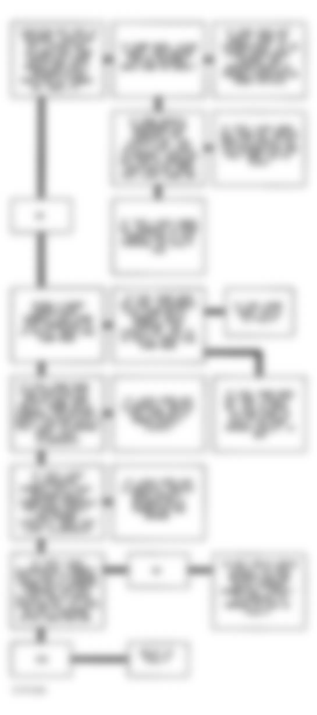
Chevrolet Lumina APV 1994 - CODE 32, EGR CIRCUIT ERROR
EGR vacuum is regulated by an ECM-controlled, normally closed solenoid. ECM will turn EGR on and off (duty cycle) by grounding and ungrounding solenoid drive circuit. Duty cycle is calculated by ECM based on coolant temperature, airflow and engine RPM. ECM will check EGR operation when vehicle speed is greater than 50 MPH, MAP is within calibrated range, throttle angle is 8-30 percent and throttle angle is constant. With ignition on and engine stopped, EGR solenoid is de-energized. Grounding ALDL test terminal should energize solenoid, allowing vacuum to pass through to EGR valve.
NOTE: Test numbers refer to numbers on diagnostic chart.
- To check for plugged intake passage, turn ignition off. Remove EGR valve from intake. Plug exhaust side passage with a suitable stopper. With intake side open, attempt to start engine. If engine runs at a very high idle (up to 3000 RPM is possible) or starts and stalls, EGR intake passage is not plugged. If engine starts and idles normally, intake passage is plugged. To check for plugged exhaust passage, with EGR valve still removed, plug intake passage with a suitable stopper. Start engine. If no exhaust gas is present, passage is plugged.
- By grounding ALDL test terminal "B", EGR solenoid should energize, allowing vacuum to pass through solenoid. Vacuum may slowly bleed off. What is important is that vacuum passes through solenoid.
- When the ALDL test terminal "B" is ungrounded, vacuum should bleed off through a vent in the solenoid valve. What is important is that vacuum no longer exists on EGR side of solenoid.
- This test will determine if the electrical control part of the system is at fault or if the connector or solenoid valve is at fault.
- The remaining test checks the ability of the EGR valve to interact with exhaust system. This is a negative backpressure EGR valve which should hold vacuum with engine off.
- When engine is started, vacuum should vent and EGR valve should seat.
Chevrolet Lumina APV 1994 - Diagnostic Aids
The EGR system may become inoperative if the park/neutral switch is out of adjustment.
Chevrolet Lumina APV 1994 - CODE 33, MAP SENSOR SIGNAL VOLTAGE HIGH
Manifold Absolute Pressure (MAP) sensor responds to changes in manifold pressure (vacuum). If MAP sensor fails, ECM will substitute a fixed MAP value and use TPS input to control fuel delivery.
NOTE: Test numbers refer to test numbers on diagnostic chart.
- This test confirms Code 33 and determines if it is a hard failure or an intermittent condition. Code 33 will set when voltage signal reading is too high and TPS voltage indicates throttle is closed.
- This step simulates conditions for a Code 34. If ECM recognizes and indicates low MAP signal, ECM and 5-volt reference and MAP signal circuits are not at fault.
Chevrolet Lumina APV 1994 - Diagnostic Aids
With ignition switch in ON position and engine off, manifold pressure is equal to atmospheric pressure and signal voltage is high. Comparing BARO readings from a known good vehicle using the same sensor is a good way to check accuracy of suspected sensor. Readings should be within .4 volt of each other. Code 33 will also result if ground circuit is open or MAP signal circuit is shorted to voltage or to 5-volt reference circuit.
Chevrolet Lumina APV 1994 CODE 33 TERMINAL & CIRCUIT WIRING IDENTIFICATION
Application PCM Terminal Wire Color MAP Sensor Signal C11 Light Green MAP Sensor Ground A11 Orange/Black MAP Sensor Reference C14 Gray

Chevrolet Lumina APV 1994 - CODE 34, MAP SENSOR SIGNAL VOLTAGE LOW
Manifold Absolute Pressure (MAP) sensor responds to changes in manifold pressure (vacuum). If MAP sensor fails, ECM will substitute a fixed MAP value and use TPS input to control fuel delivery.
NOTE: Test numbers refer to test numbers on diagnostic chart.
- This confirms Code 34 and determines if code was a hard failure or an intermittent condition. Code 34 will set when ignition is on and MAP signal voltage is low. On some systems, engine must be running to set code.
- Jumpering harness 5-volt reference circuit and MAP signal circuit terminals will determine if problem is sensor, ECM or wiring. If ECM recognizes and indicates high MAP signal, ECM and wiring are okay.
- Scan tester may not display 12 volts. The important thing is that the ECM recognizes voltage as greater than 4 volts (high MAP voltage signal), indicating ECM and MAP signal circuit are not at fault.
Chevrolet Lumina APV 1994 - Diagnostic Aids
With ignition switch in ON position and engine off, manifold pressure is equal to atmospheric pressure and signal voltage will be high. Comparing BARO readings with a known good vehicle using the same sensor is a good way to check accuracy of suspected sensor. Readings should be within .4 volt of each other. A Code 34 will also result if 5-volt reference and MAP signal circuits are open or shorted to ground. If 5-volt reference circuit is not shorted to ground and a Code 22 is stored, check MAP signal circuit for short to ground.
Chevrolet Lumina APV 1994 CODE 34 TERMINAL & CIRCUIT WIRING IDENTIFICATION
Application PCM Terminal Wire Color MAP Sensor Signal C11 Light Green MAP Sensor Ground A11 Orange/Black MAP Sensor Reference C14 Gray

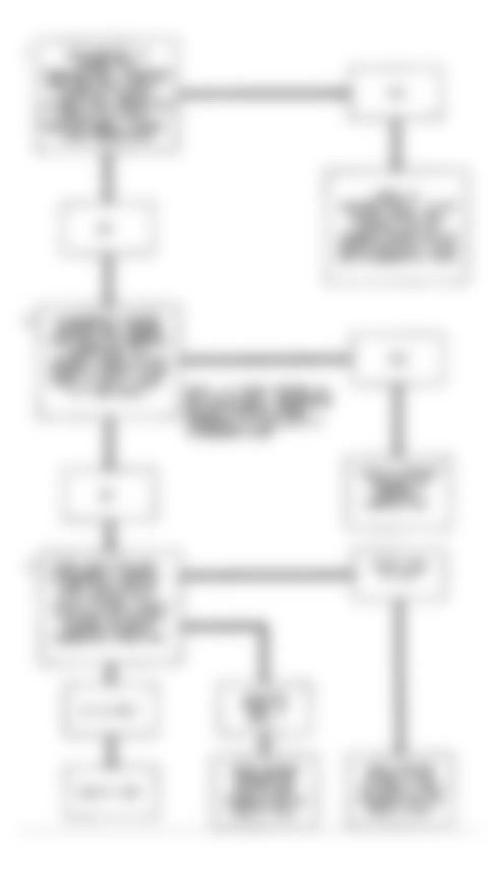
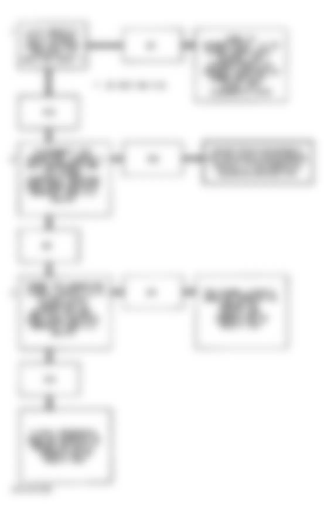
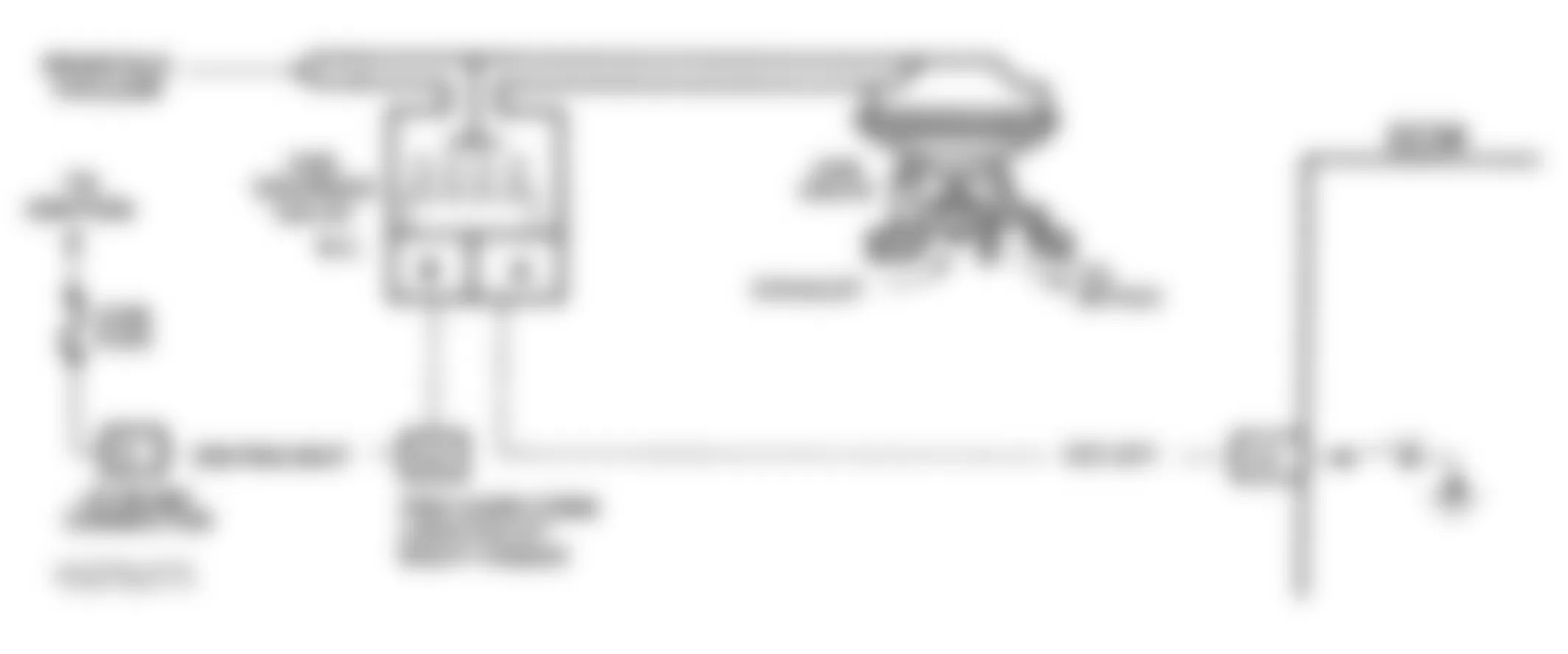
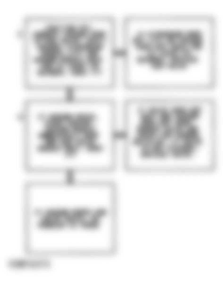
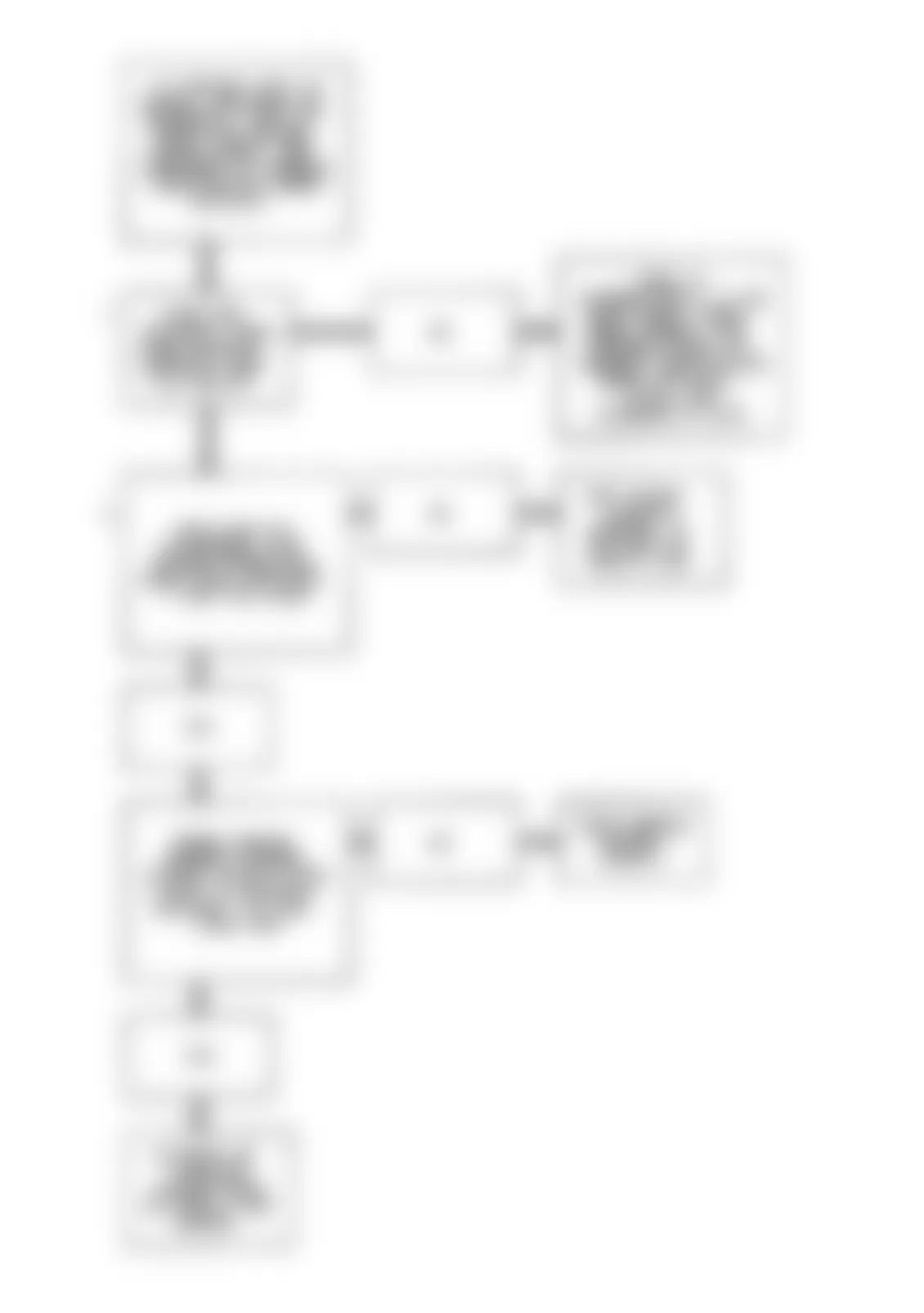
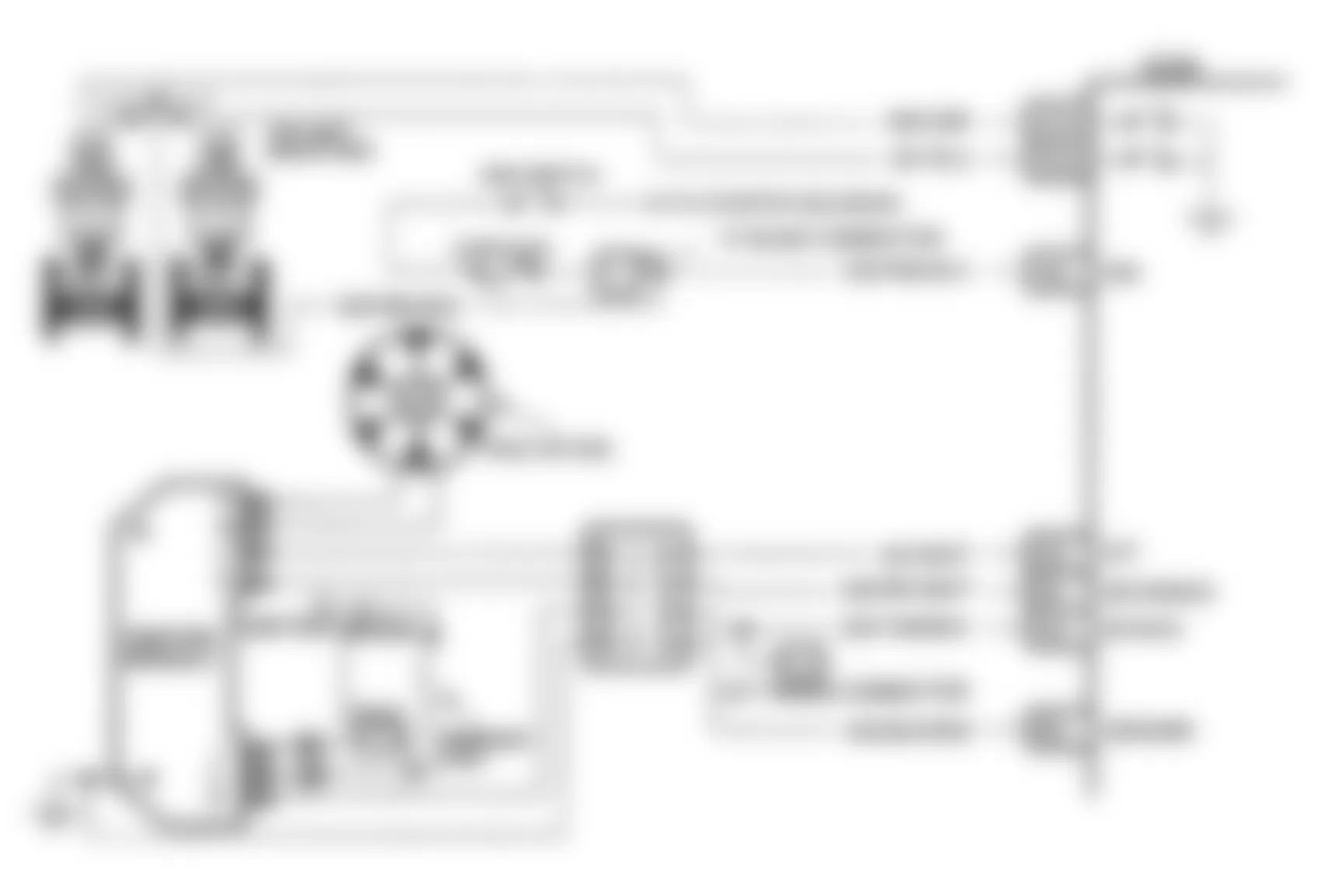
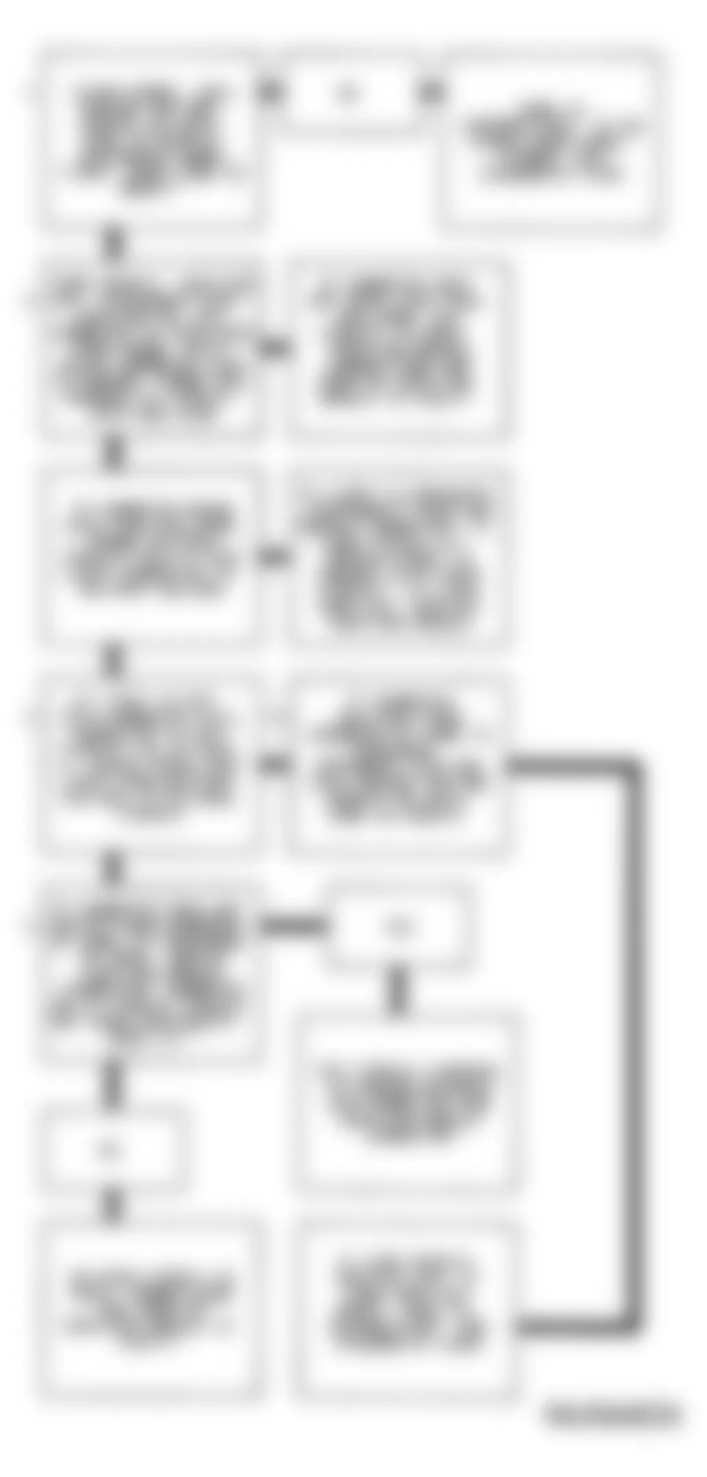
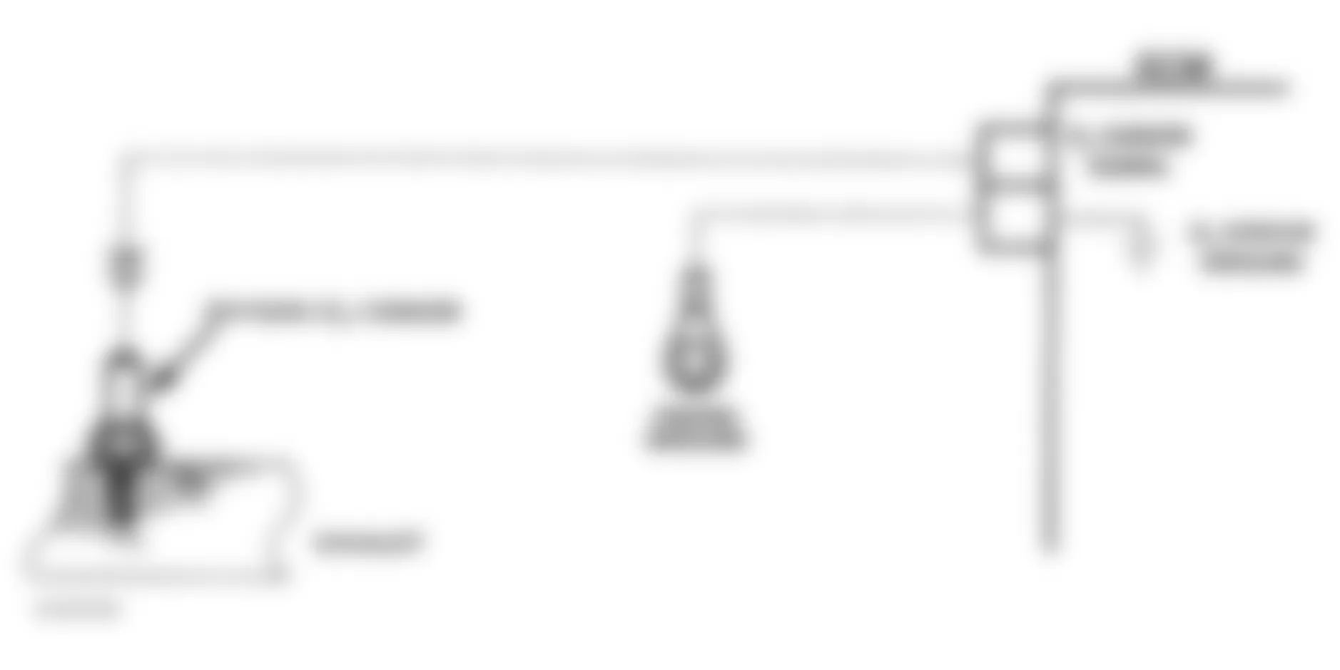
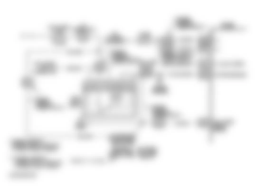
Chevrolet Lumina APV 1994 - CODE 42 - IGNITION CONTROL
Code 42 indicates ECM has seen an open or short to ground in the Ignition Control (IC) or by-pass circuits.
NOTE: Test numbers refer to test numbers on diagnostic chart.
- This test confirms Code 42 and determines if fault is a hard failure or intermittent condition.
- This tests for a normal IC ground path through ignition module. If circuit is shorted to ground, reading will be less than 500 ohms.
- As test light voltage touches by-pass circuit, module should switch. This causes ohmmeter to "over-range" with meter in 100-200 ohm range. A higher ohm range will indicate over 5000 ohms. This test assures module switched.
- If module did not switch, this step tests for a short in IC circuit, an open in by-pass circuit and a faulty ignition module connection or module.
- This step confirms Code 42 is a faulty ECM and not an intermittent problem in IC and by-pass circuits.
Chevrolet Lumina APV 1994 - Diagnostic Aids
The scan tester cannot help diagnose a Code 42 problem. See INTERMITTENTS in TESTS W/O CODES article in this section.
Fig. 21: Chevrolet Lumina APV 1994 - Component Locations - Code 42 Schematic (3.1L) Ignition Control
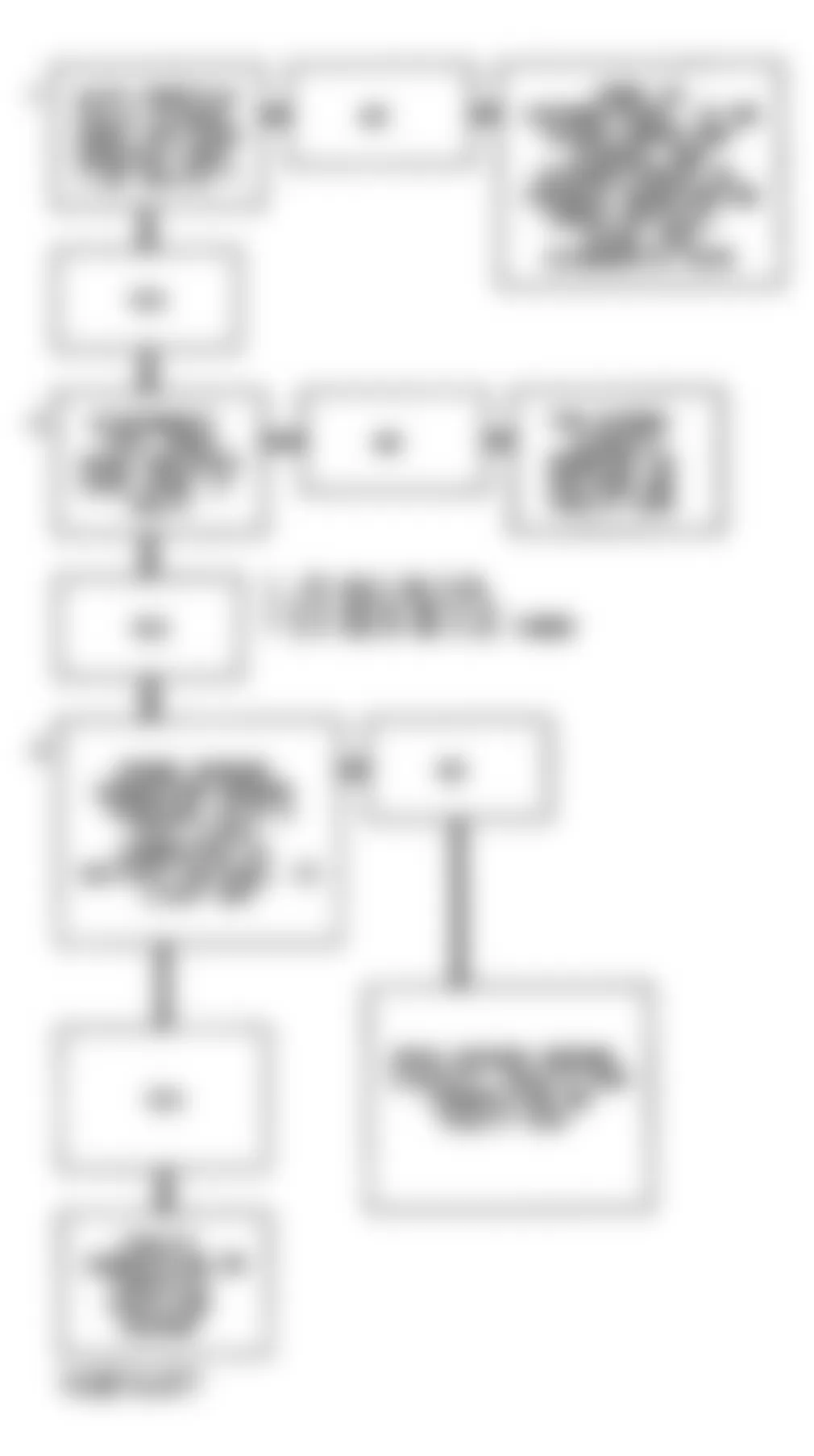
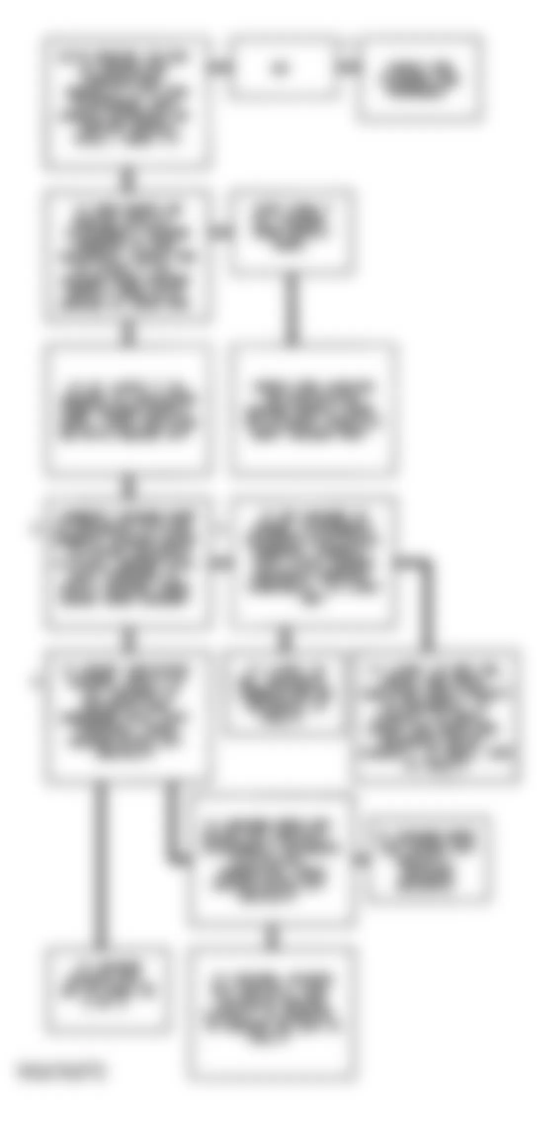
Chevrolet Lumina APV 1994 - CODE 43, KNOCK SENSOR WITH SPARK CONTROL MODULE
NOTE: Test numbers refer to test numbers on diagnostic chart.
- If conditions for a Code 43 exist, scan tester will display YES. A knock signal should exist at idle unless an internal or system problem exists.
- Determines if system is functioning. Usually, a knock signal can be made by tapping on exhaust manifold. If knock signal is not made, try tapping on engine block near sensor. On models with automatic transmission, it may be necessary to place gear selector lever in Drive.
- Because Code 43 sets when signal voltage on spark retard line remains low, this test should cause signal on that line to go high. The 12-volt signal should be seen by ECM as a "no knock" signal if ECM and wiring are okay.
- This test determines if knock signal is detected on sensor-to-controller line or if ESC module is at fault.
- If sensor line is routed too close to secondary ignition wires, ESC module may see interference as a knock signal.
- This checks ground circuit to module. An open ground will cause voltage on monitored line to remain constant at about 12 volts. This would cause Code 43 functional test to fail.
- This should generate a knock signal to controller. This determines if ESC controller is operating correctly.
Chevrolet Lumina APV 1994 - Diagnostic Aids
Code 43 can be caused by a faulty knock sensor connection at ESC module or ECM. Also, check controller-to-ECM signal line for an open or short to ground.

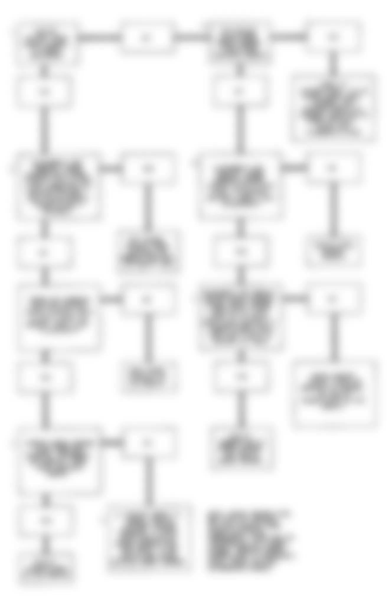
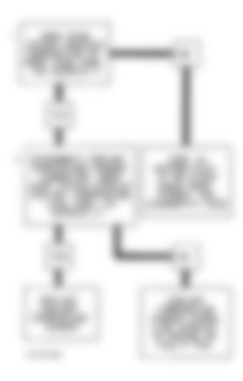
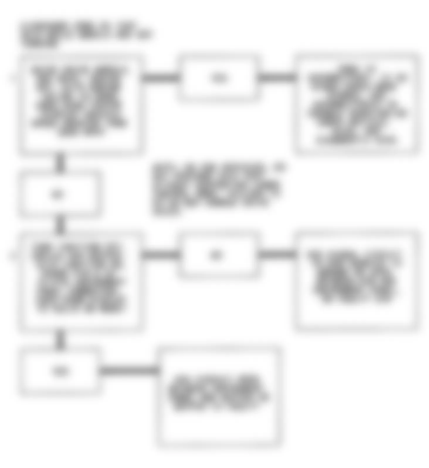
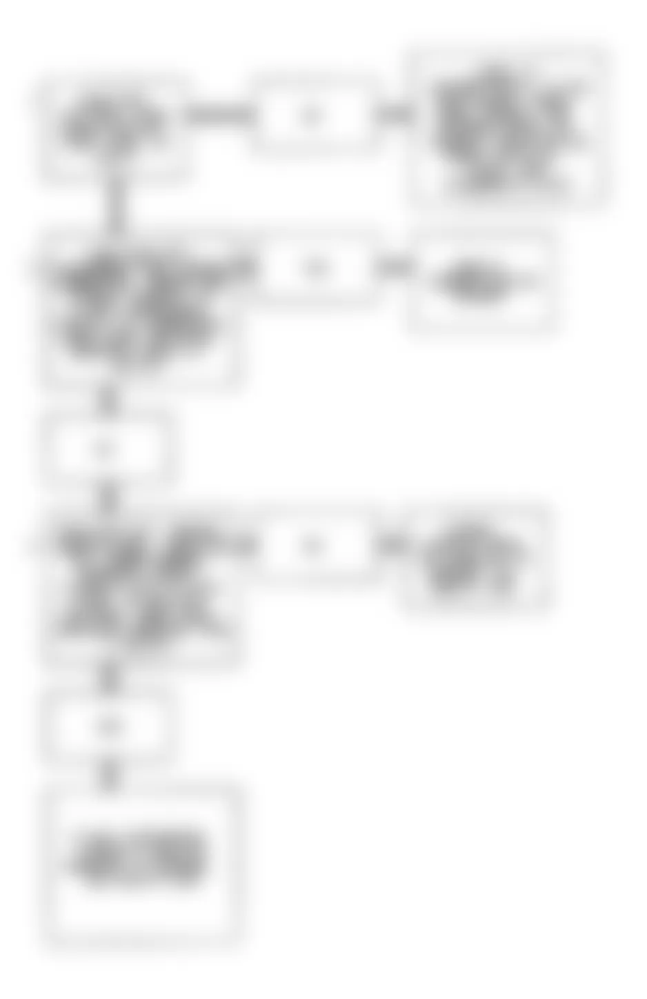
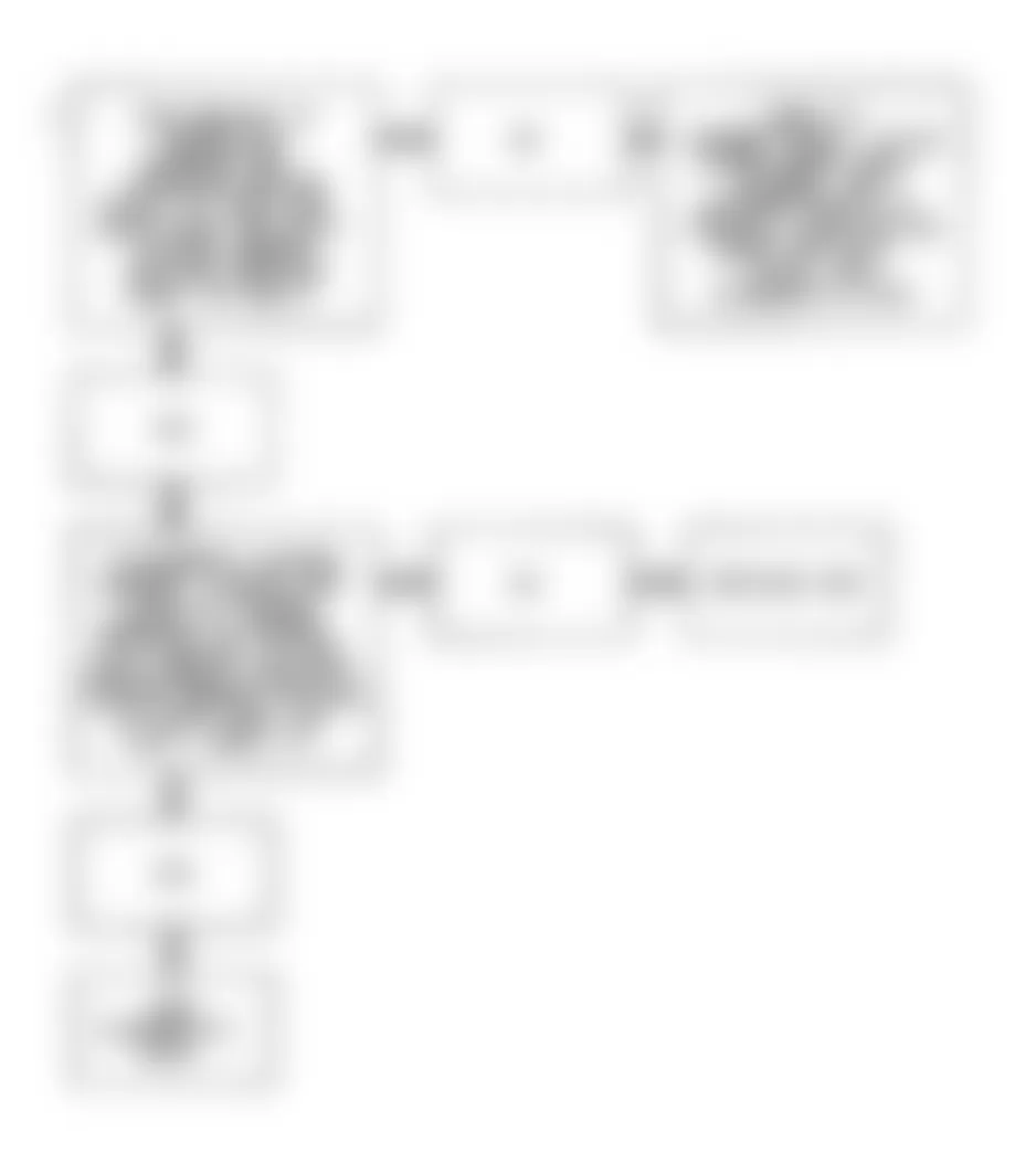
Chevrolet Lumina APV 1994 - CODE 44, LEAN EXHAUST INDICATION
Sensor acts like an open sensor circuit and produces no voltage when exhaust temperature is less than 600?F (316?C). An open sensor circuit or cold sensor causes "open loop" operation.
NOTE: Test numbers refer to test numbers on diagnostic chart.
- Code 44 sets when O2 sensor signal remains low for a precalibrated period and system is operating in "closed loop".
Chevrolet Lumina APV 1994 - Diagnostic Aids
Using scan tester, observe Block Learn Memory (BLM) value at different RPMs. If Code 44 conditions exist, block learn value will be around 150-172.
Chevrolet Lumina APV 1994 - O2 Sensor Wire
Wire may be mispositioned and touching exhaust manifold. Check for ground between sensor and wire connector.
Chevrolet Lumina APV 1994 - Fuel Contamination
Water, even small amounts, near in-tank fuel pump inlet can reach fuel injector, causing a lean exhaust and setting Code 44.
Chevrolet Lumina APV 1994 - Fuel Pressure
System will be lean if fuel pressure is low. It may be necessary to monitor fuel pressure while driving vehicle. For fuel pressure checking procedure, see BASIC TESTING article in this section.
Chevrolet Lumina APV 1994 - Exhaust Leaks
If exhaust system has large leaks, exhaust system negative pressure pulses can cause outside air to be drawn into system and past O2 sensor. Vacuum or crankcase leaks can also cause a lean condition.
If Code 44 is intermittent, see INTERMITTENTS in TESTS W/O CODES article in this section.
Chevrolet Lumina APV 1994 CODE 44 TERMINAL & CIRCUIT WIRING IDENTIFICATION
Application PCM Terminal Wire Color Oxygen Sensor Signal D7 Purple Oxygen Sensor Ground D6 Tan

Fig. 27: Chevrolet Lumina APV 1994 - Component Locations - Code 44 Flow Chart

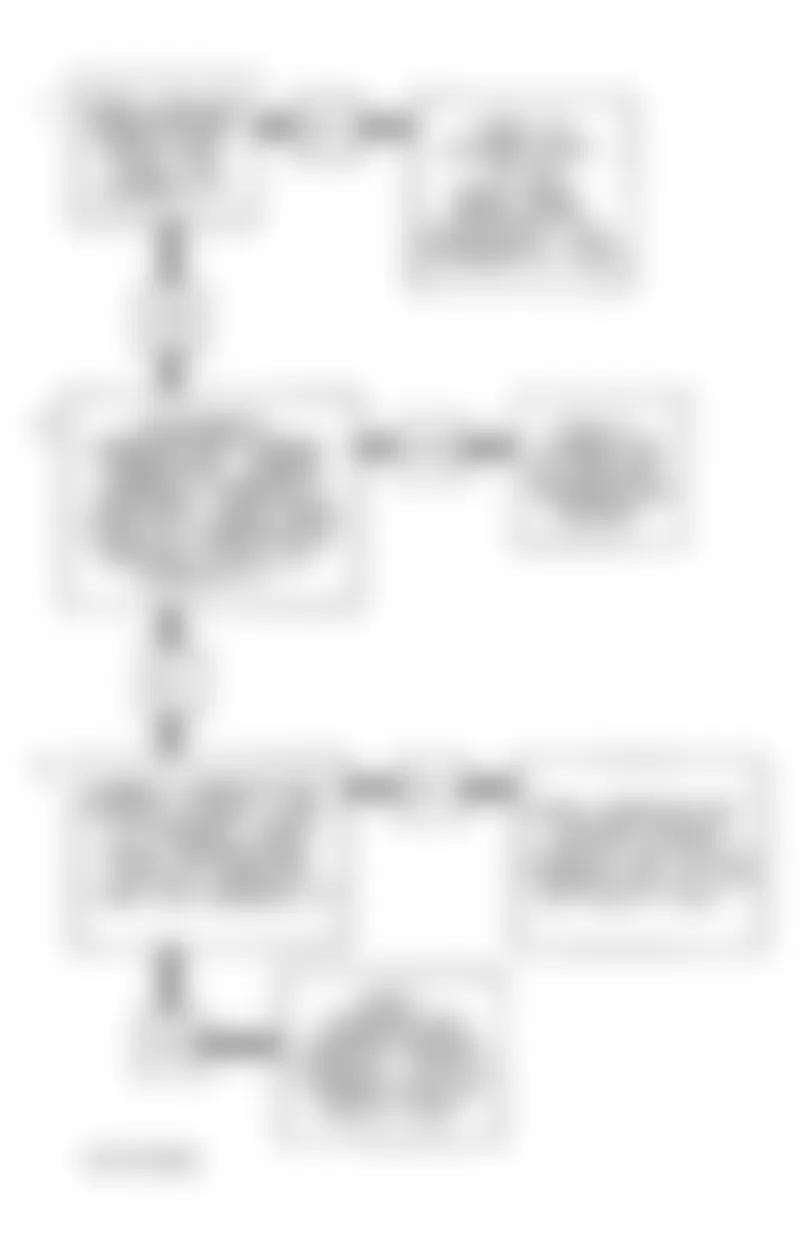
Chevrolet Lumina APV 1994 - CODE 45, RICH EXHAUST INDICATION
Sensor acts like an open sensor circuit and produces no voltage when exhaust temperature is less than 600?F (316?C). An open sensor circuit or cold sensor causes "open loop" operation. Code 45 indicates a rich exhaust and diagnosis should begin with: fuel pressure, leaking injector, HEI shielding, canister purge saturation, coolant sensor, MAP sensor, O2 sensor contamination and TPS intermittent output.
NOTE: Test numbers refer to test numbers on diagnostic chart.
- Tests if O2 sensor is registering a rich condition. Code 45 is set when vehicle is at operating temperature (in "closed loop"), throttle angle is greater than 5 percent, O2 sensor signal at ECM is greater than .75 volt for 60 seconds or more.
Chevrolet Lumina APV 1994 - Diagnostic Aids
Code 45, rich exhaust, is most likely caused by one of the following:
Chevrolet Lumina APV 1994 - Fuel Pressure High
If fuel pressure is too high, air/fuel ratio will be rich. For fuel pressure checking procedure, see BASIC TESTING article in this section. The ECM can compensate for slight increases but if air/fuel ratio becomes too rich a Code 45 will be set.
Chevrolet Lumina APV 1994 - Ignition Ground
If an open occurs at circuit No. 453, HEI induced electrical "noise" may result, causing simulated reference pulses picked up by ECM on EST harness reference line. Additional pulses result in a higher than actual engine speed signal. The ECM will increase injector pulse width ("on" time) to match increased RPM signal. Scan tester will show higher than actual RPM, which can help diagnose problem.
Chevrolet Lumina APV 1994 - Fuel Canister
Charcoal canister fuel saturation will cause a rich air/fuel ratio. If full of fuel, check canister control and hoses.
Chevrolet Lumina APV 1994 - MAP Sensor
If ECM senses higher than normal manifold pressure (low vacuum) system can go rich. Disconnecting MAP sensor allows ECM to substitute a fixed value for the MAP sensor. If rich condition disappears, replace MAP sensor and continue testing.
Chevrolet Lumina APV 1994 - TPS
An intermittent TPS output will cause system to operate rich due to a false indication of engine acceleration.
Chevrolet Lumina APV 1994 - O2 Sensor Contamination
O2 sensor contamination, caused by silicone in certain fuels or use of improper RTV sealant, may cause a White-powdery coating to cover O2 sensor. The false high signal voltage produced (or low oxygen content sensed) is interpreted by ECM as a rich mixture, causing ECM to set Code 45.
Chevrolet Lumina APV 1994 - EGR Problem
EGR valve sticking open at idle is usually accompanied by a rough idle and/or stalling. If Code 45 is intermittent, see INTERMITTENTS in TESTS W/O CODES article in this section.
Chevrolet Lumina APV 1994 CODE 45 TERMINAL & CIRCUIT WIRING IDENTIFICATION
Application PCM Terminal Wire Color Oxygen Sensor Signal D7 Purple Oxygen Sensor Ground D6 Tan
Chevrolet Lumina APV 1994 - CODE 51, PROM ERROR (FAULTY OR INCORRECT PROM)
Ensure all pins are fully inserted in socket. If okay, replace PROM/MEM-CAL, clear memory and recheck. If Code 51 reappears, replace ECM.
Chevrolet Lumina APV 1994 - CODE 52, FAULTY CALPAK
Ensure all pins are fully inserted in socket. If okay, replace CALPAK, clear memory and recheck. If Code 51 reappears, replace ECM.
Chevrolet Lumina APV 1994 - CODE 53, SYSTEM OVERVOLTAGE
This code indicates a basic charging system problem. Code 53 will set when voltage at ECM terminal is greater than 17.1 volts for 2 seconds. Check and repair charging system.
Chevrolet Lumina APV 1994 - CODE 55, ECM/PCM ERROR
Ensure ECM grounds are good and MEM-CAL is properly latched. If okay, replace ECM/PCM. Clear codes and confirm closed loop operation. Check operation of SERVICE ENGINE SOON light.
Chevrolet Lumina APV 1994 - CODE 54, FUEL PUMP CIRCUIT
The status of fuel pump signal is monitored by the control module and is used to compensate fuel delivery based on system voltage. Signal is also used to store Code 54 if fuel pump relay is defective or if relay voltage is lost after engine is running. Voltage should be present at fuel pump signal terminal of control module the first 2 seconds after ignition is turned on and anytime reference (RPM) pulses are being received by control module.
Chevrolet Lumina APV 1994 - SUMMARY
If hard fault codes are not present and driveability symptoms or intermittent codes exist, proceed to TESTS W/O CODES article in this section for diagnosis by symptom (i.e., ROUGH IDLE, NO START, etc.), or intermittent diagnostic procedures.