Chevrolet Monte Carlo SS 2006 - 2006 GENERAL MOTORS Impala & Monte Carlo
Chevrolet Monte Carlo SS 2006 - BUZZERS, RELAYS & TIMERS
Chevrolet Monte Carlo SS 2006 BUZZERS, RELAYS & TIMERS LOCATION
Component Location A/C CMPRSR Relay In underhood fuse block. See Fig. 69. FAN 1 Relay In underhood fuse block. See Fig. 69. FAN 2 Relay In underhood fuse block. See Fig. 69. FAN 3 Relay In underhood fuse block. See Fig. 69. FUEL/PUMP Relay In underhood fuse block. See Fig. 69. PWR/TRN Relay In underhood fuse block. See Fig. 69. REAR DEFOG Relay In underhood fuse block. See Fig. 69. STRTR Relay In underhood fuse block. See Fig. 69.
Chevrolet Monte Carlo SS 2006 - CIRCUIT PROTECTION DEVICES
Chevrolet Monte Carlo SS 2006 CIRCUIT PROTECTION DEVICES LOCATION
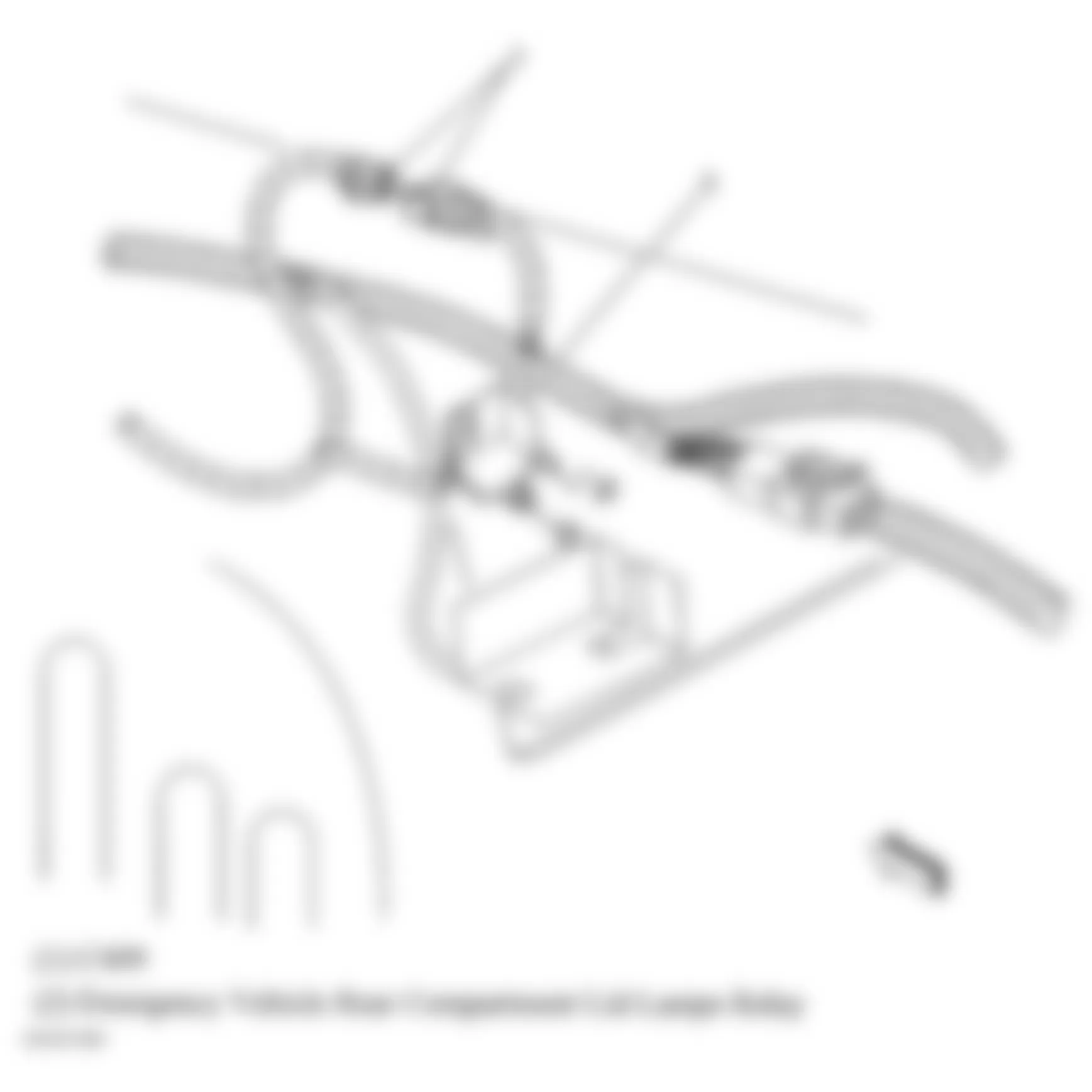
Component Location Emergency Vehicle Rear Compartment Lid Lamps Relay Right front of rear compartment. See Fig. 86. Fusible Link (Except Police) Near starter. Fusible Links (Police) At underhood battery stud. See Fig. 63. I/P Fuse Block In right front kick panel. See Fig. 66. Rear Junction Block In rear compartment, behind right rear wheelhouse. See Fig. 39. SEO Fuse Block Above accelerator pedal. See Fig. 64. Terminator Resistor (W/ GPS) In body harness, left side of rear compartment. See Fig. 8. Terminator Resistor (W/O GPS) In body harness, near connector C203. See Fig. 11. Underhood Fuse Block Mounted to right strut tower. See Fig. 34.
Chevrolet Monte Carlo SS 2006 - CONTROL UNITS
Chevrolet Monte Carlo SS 2006 CONTROL UNITS LOCATION
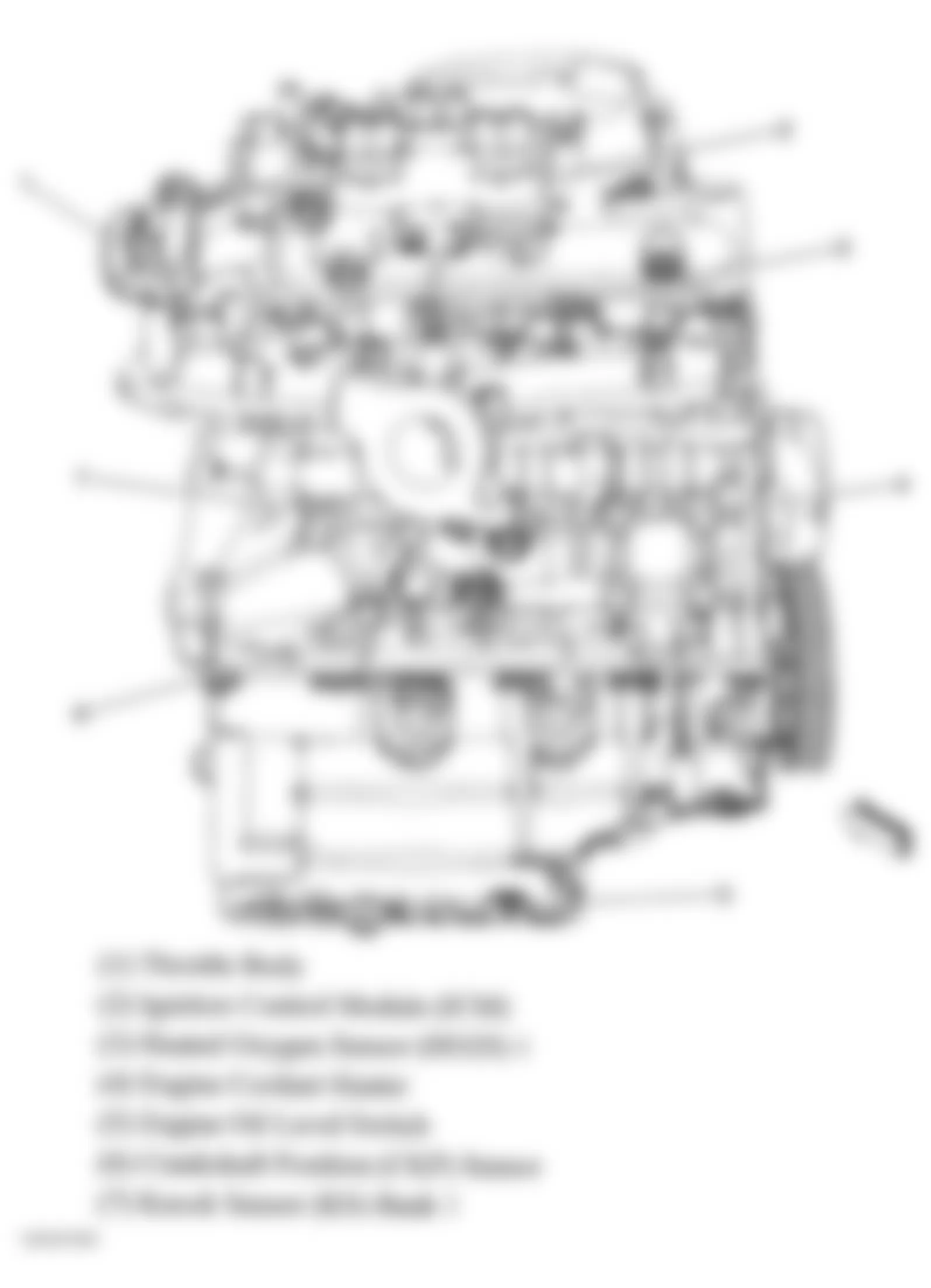
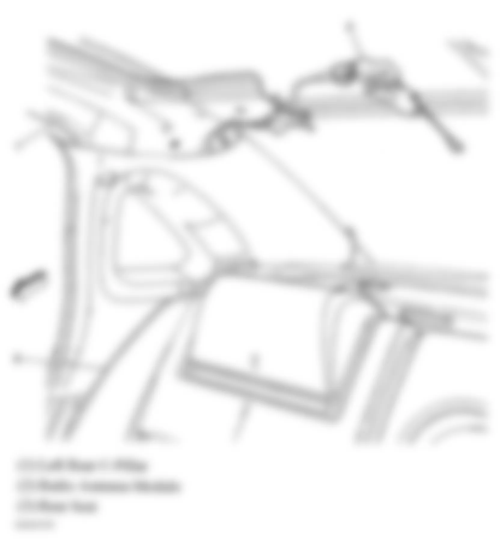
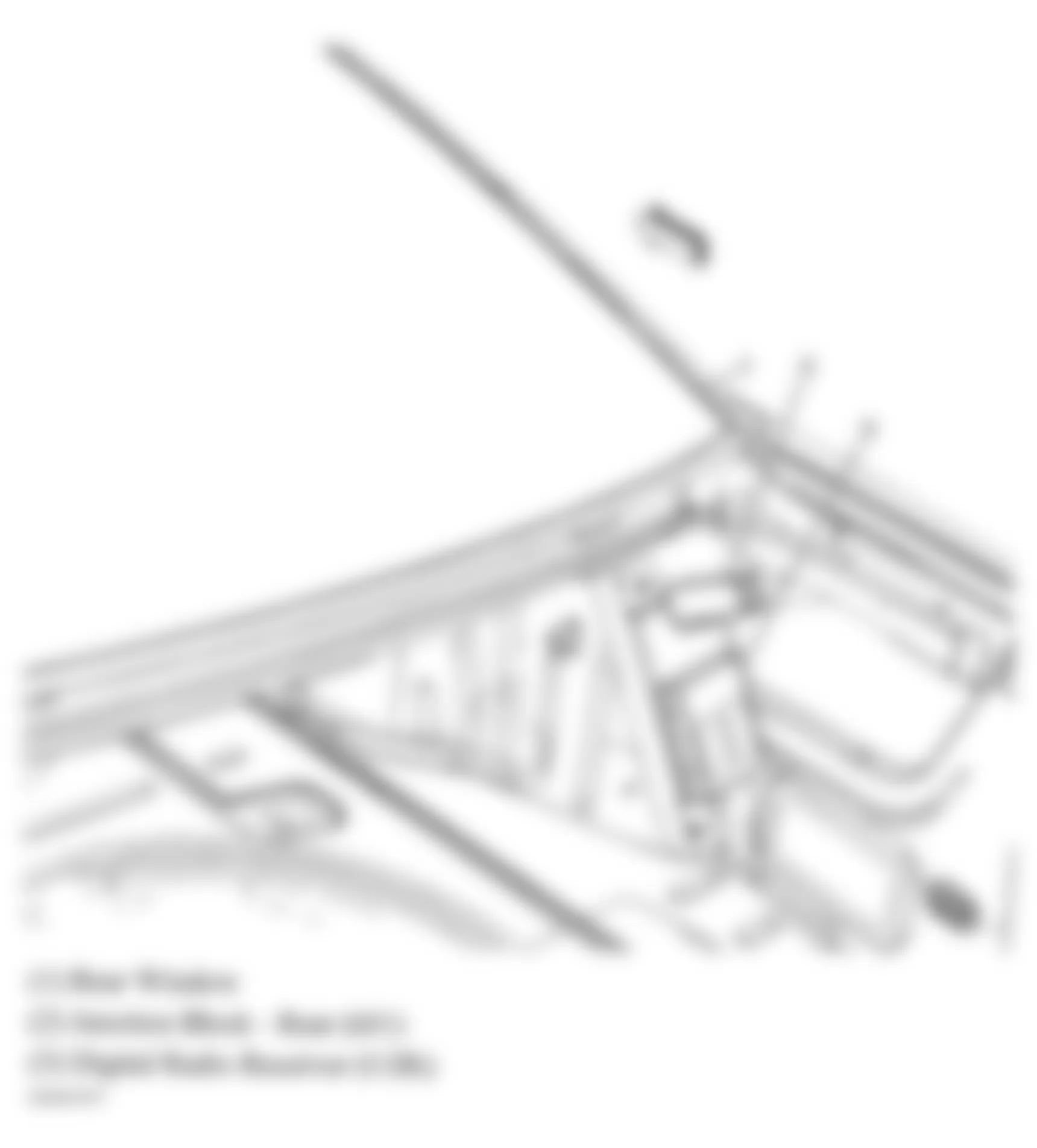
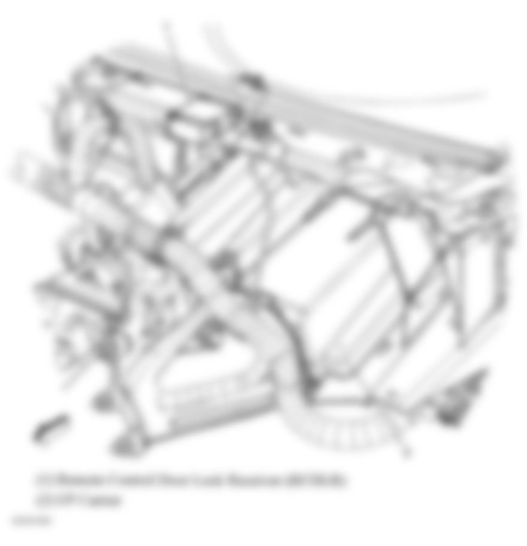
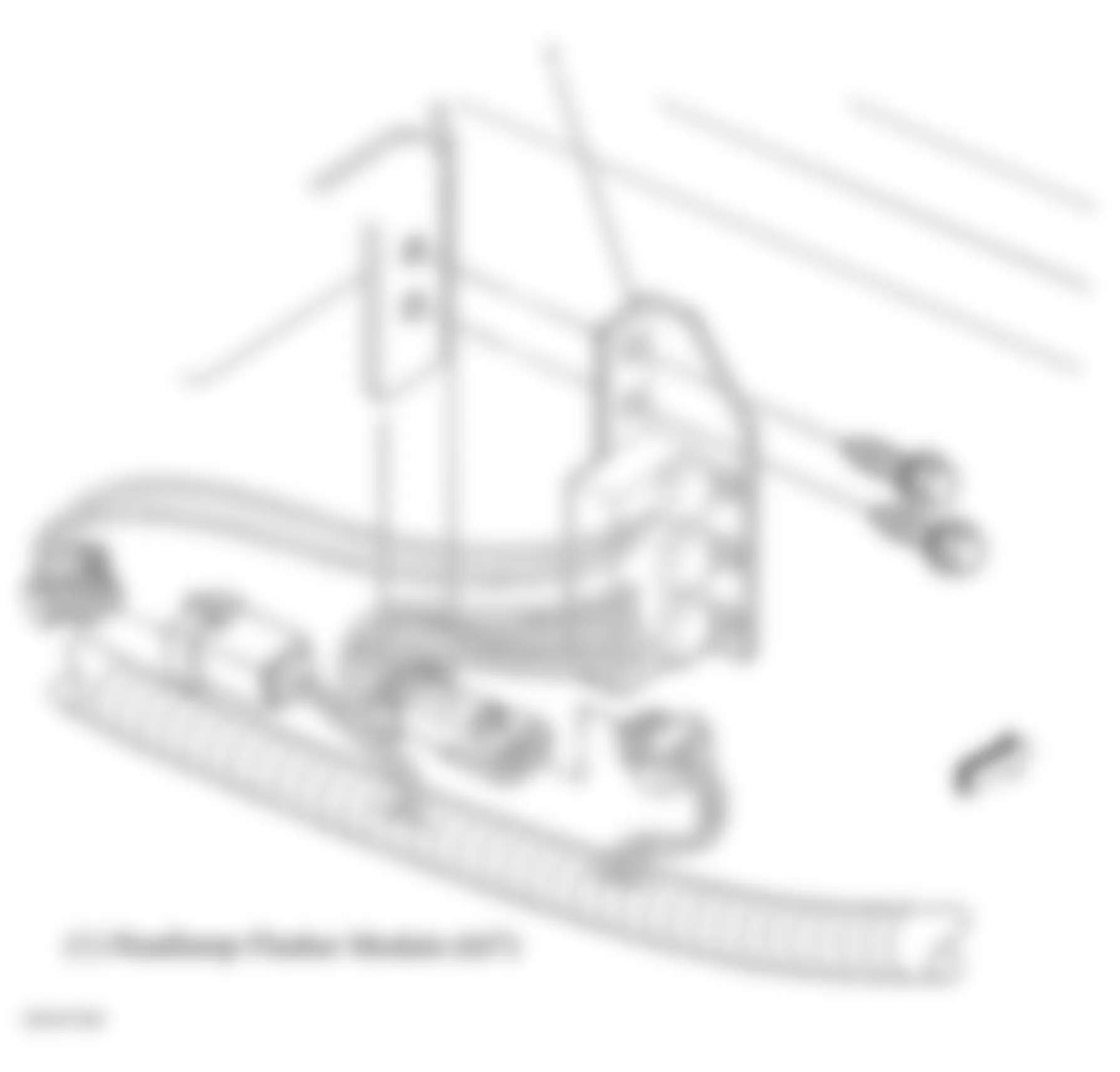
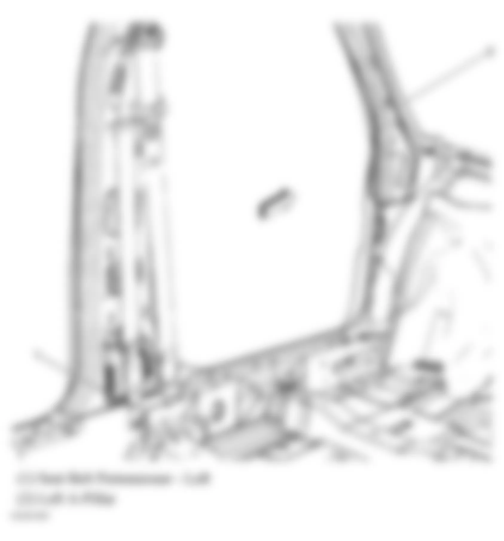
Component Location Blower Motor Control Processor Lower right side of dash. See Fig. 41. Body Control Module (BCM) Left of steering column. See Fig. 9. Electronic Brake Control Module (EBCM) Part of brake pressure modulator valve. See Fig. 1. Engine Control Module (ECM) Inside air cleaner assembly. See Fig. 1. Headlamp Flasher Module At left side of right headlamp assembly. See Fig. 46. Heated Seat Control Module Under driver seat. See Fig. 56. HVAC Control Module Center of dash. See Fig. 41. Ignition Control Module (ICM) Top rear center of engine. See Fig. 20. Inflatable Restraint Front Passenger Presence System (PPS) Module Under front passenger seat. See Fig. 50. Inflatable Restraint I/P Module Right side of instrument panel, above I/P compartment. See Fig. 37. Inflatable Restraint Sensing & Diagnostic Module (SDM) Under front passenger seat, under carpet. See Fig. 51. Inflatable Restraint Side Impact Module - Left On left side of driver seat back. See Fig. 53. Inflatable Restraint Side Impact Module - Right On right side of front passenger seat back. See Fig. 53. Inflatable Restraint Steering Wheel Module Center of steering wheel. See Fig. 9. Radio Antenna Module Left of back window. See Fig. 38. Remote Control Door Lock Receiver (RCDLR) Under defroster grill panel. See Fig. 45. Roof Rail Module - Left Mounted on left "C" pillar. See Fig. 54. Roof Rail Module - Right Mounted on right "C" pillar. See Fig. 54. Theft Deterrent Exciter Module Around ignition key cylinder housing. See Fig. 59. Transmission Control Module (TCM) Left side of engine compartment in with air cleaner. See Fig. 5. Vehicle Communication Interface Module (VCIM) Mounted to rear of left rear wheelhouse. See Fig. 8.
Chevrolet Monte Carlo SS 2006 - MOTORS
Chevrolet Monte Carlo SS 2006 MOTORS LOCATION
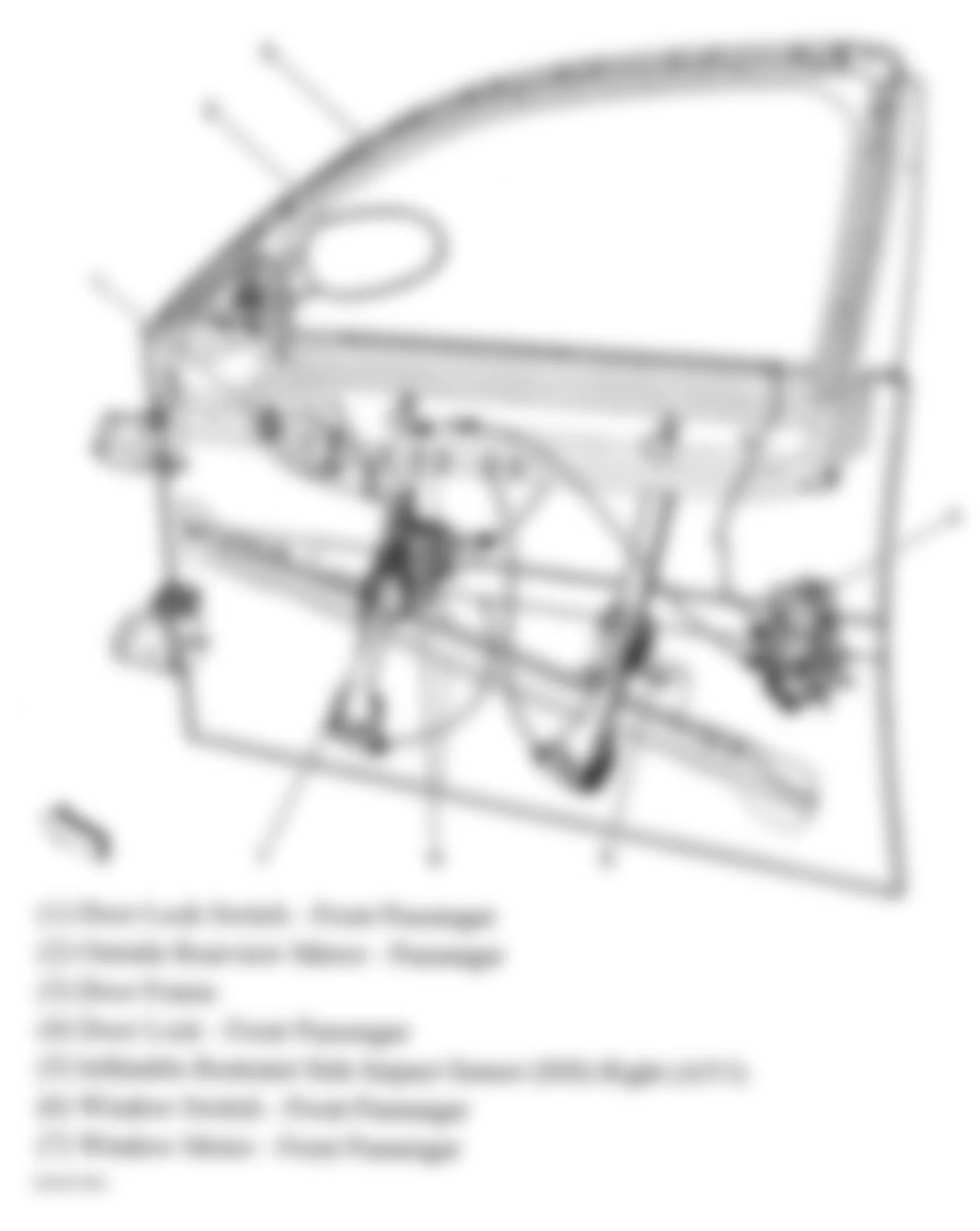
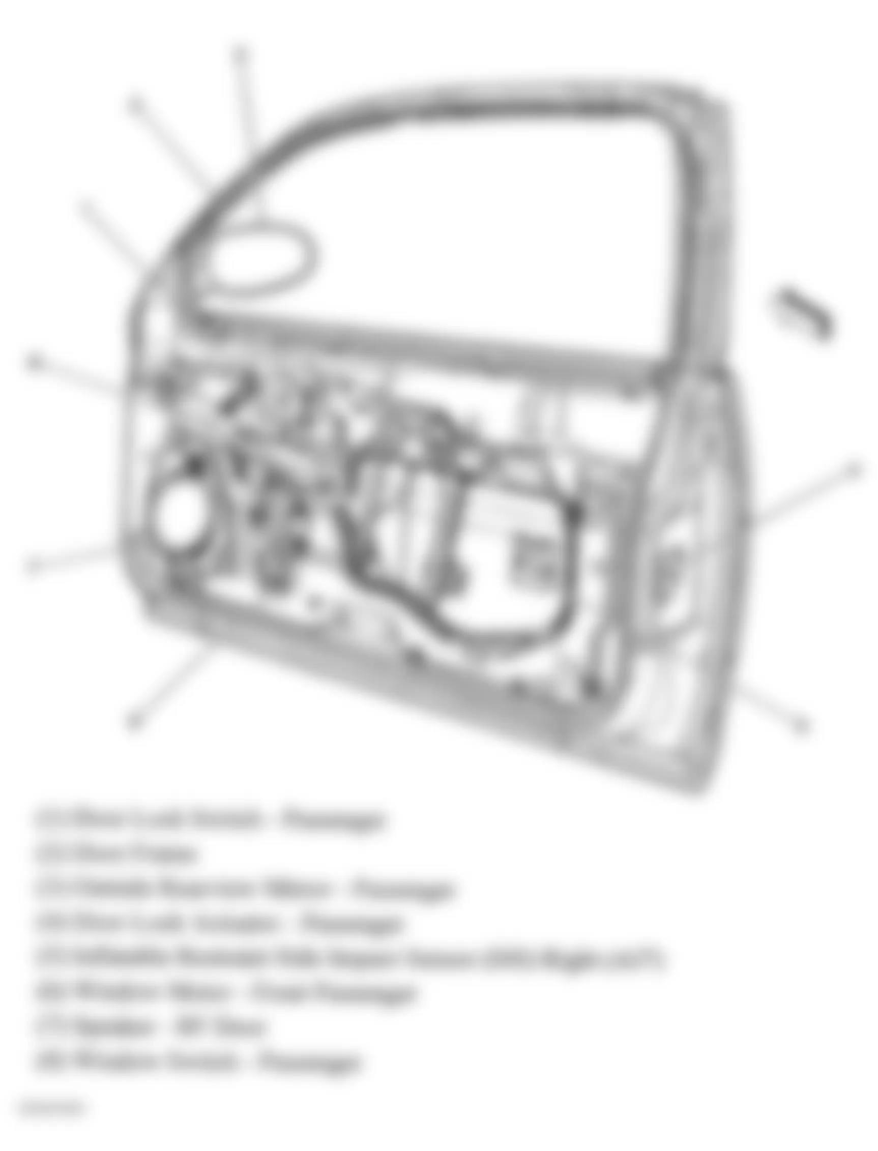
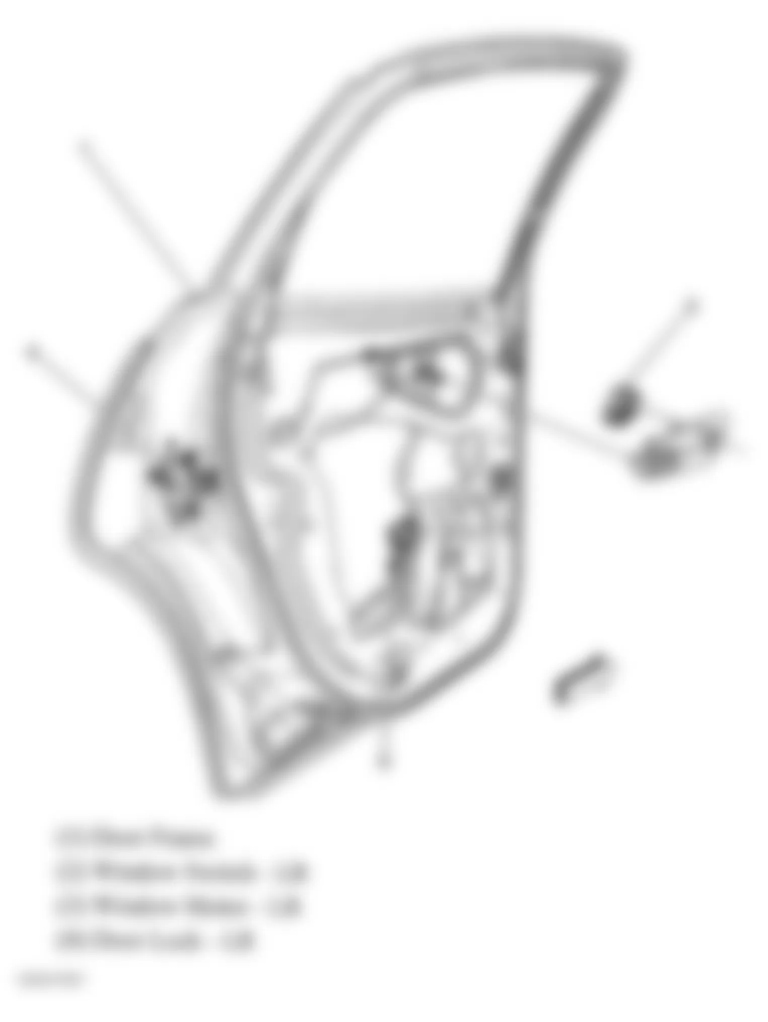
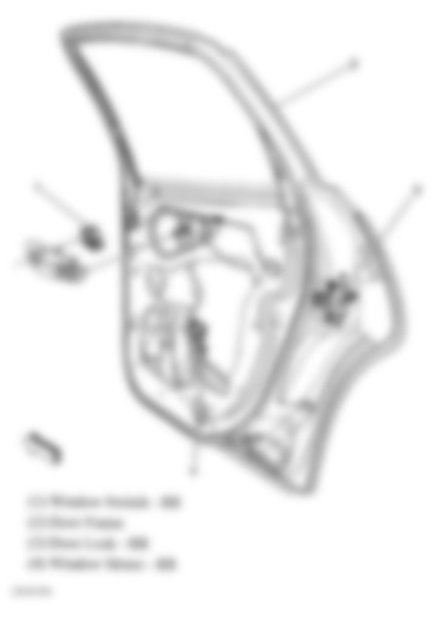
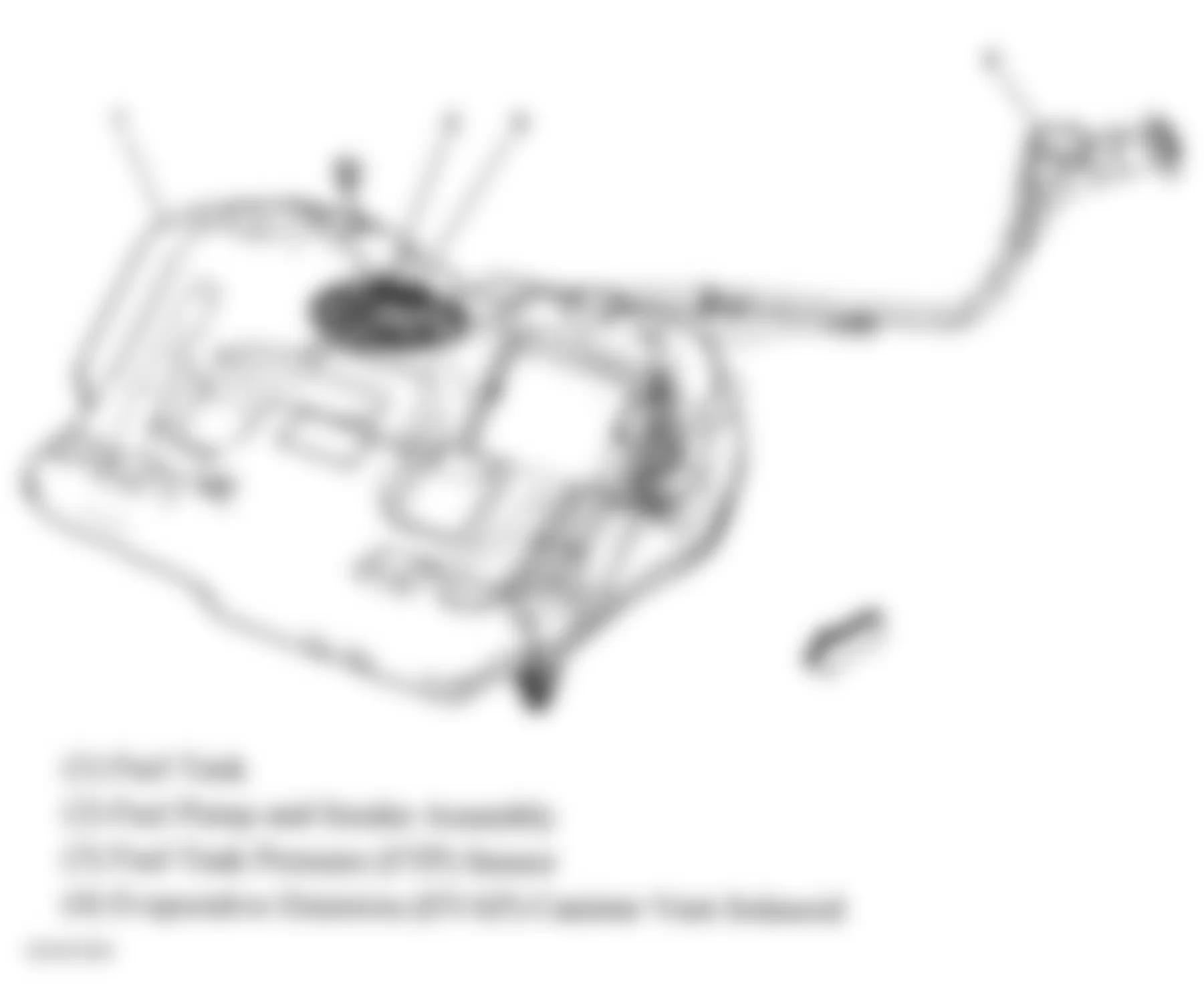
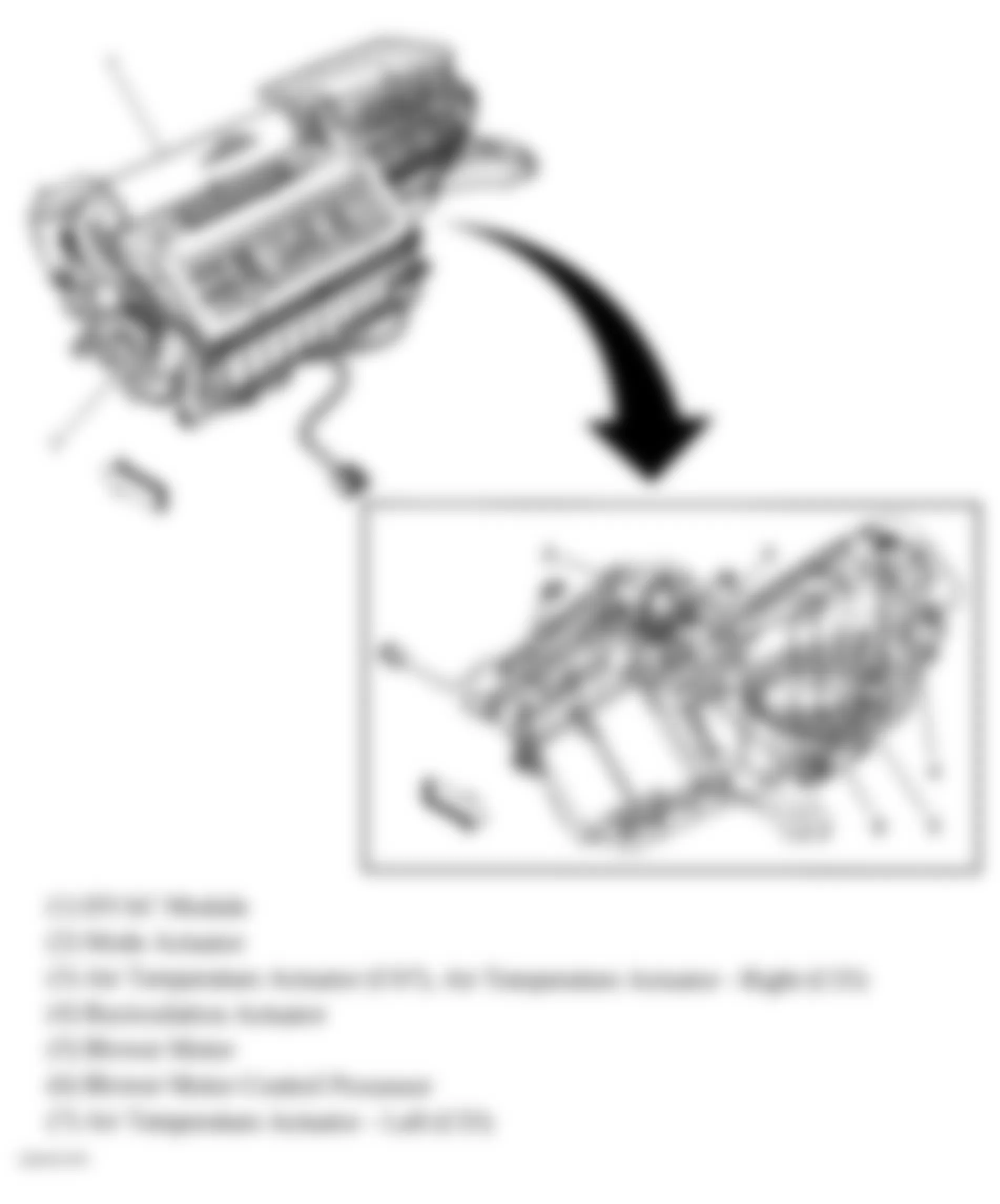
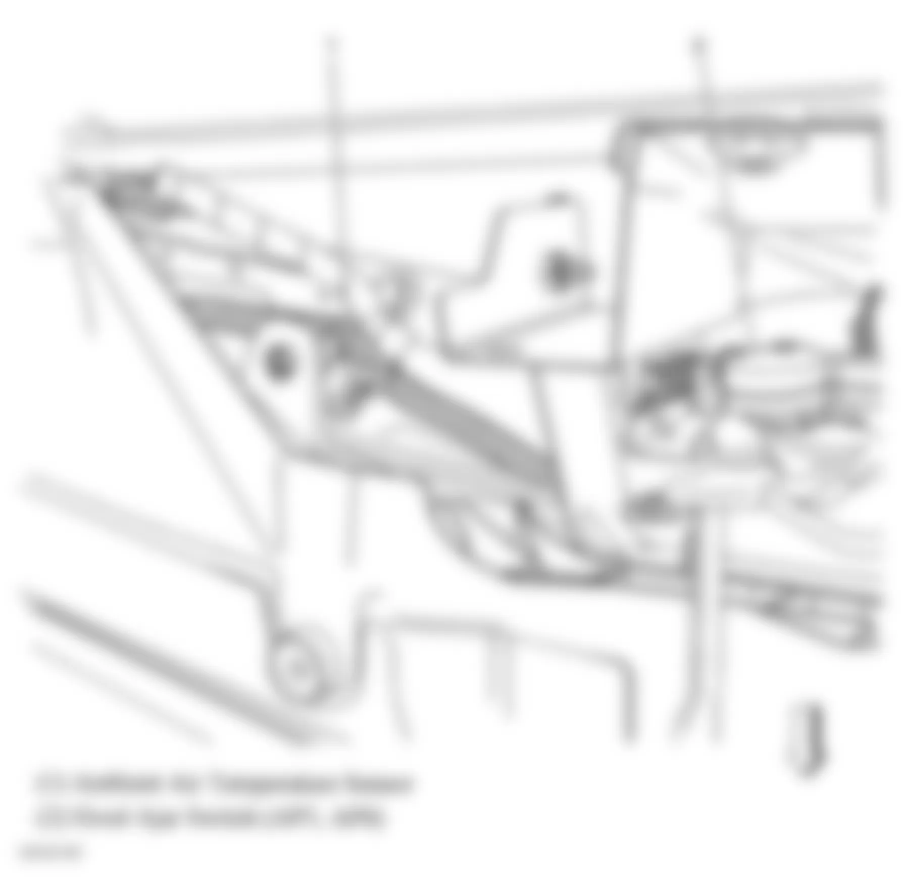
Component Location Air Temperature Actuator Behind center of I/P on HVAC case. See Fig. 41. Air Temperature Actuator - Left Right of accelerator pedal. See Fig. 41. Air Temperature Actuator - Right Behind center of dash, on HVAC case. See Fig. 41. Blower Motor Above foot area of passenger floor. See Fig. 41. Cooling Fan - Left Front of engine compartment, mounted to left side of radiator. See Fig. 31. Cooling Fan - Right Mounted to right side of radiator. See Fig. 31. Door Lock Actuator - Driver Rear of driver door. See Fig. 13. Door Lock Actuator - Passenger Rear of passenger door. See Fig. 15. Fuel Pump In fuel tank assembly. See Fig. 30. Fuel Pump & Sender Assembly Top of fuel tank. See Fig. 25. Horizontal Motor In seat back. See Fig. 50. Ignition Lock Cylinder Control Actuator In steering column. See Fig. 59. Mode Actuator On HVAC assembly. See Fig. 41. Rear Compartment Lid Release Actuator Center of deck lid. See Fig. 6. Recirculation Actuator On right side of HVAC case. See Fig. 41. Seat Adjuster Motor Assembly - Driver Below driver seat. Seat Adjuster Motor Assembly - Passenger Below front passenger seat. Seat Recline Motor - Driver Attached to right side of driver seat back. See Fig. 56. Starter Lower front of engine, at transaxle. See Fig. 32. Sunroof Motor Front center of sunroof module. See Fig. 7. Vertical Motor (Front) In seat back. See Fig. 50. Vertical Motor (Rear) In seat back. See Fig. 50. Window Motor-Driver (Coupe) Center of door. See Fig. 13. Window Motor - Driver (Sedan) Center of driver door. See Fig. 12. Window Motor-Front Passenger (Coupe) Center of front passenger door. See Fig. 15. Window Motor - Front Passenger (Sedan) Center of front passenger door. See Fig. 14. Window Motor - LR Center of left rear door. See Fig. 16. Window Motor - RR Center of right rear door. See Fig. 17. Windshield Washer Fluid Pump In lower portion of washer fluid container. See Fig. 34. Windshield Wiper Motor In left side cowl panel, below air inlet screen. See Fig. 1.
Chevrolet Monte Carlo SS 2006 - SENDING UNITS & SENSORS
Chevrolet Monte Carlo SS 2006 SENDING UNITS & SENSORS LOCATION
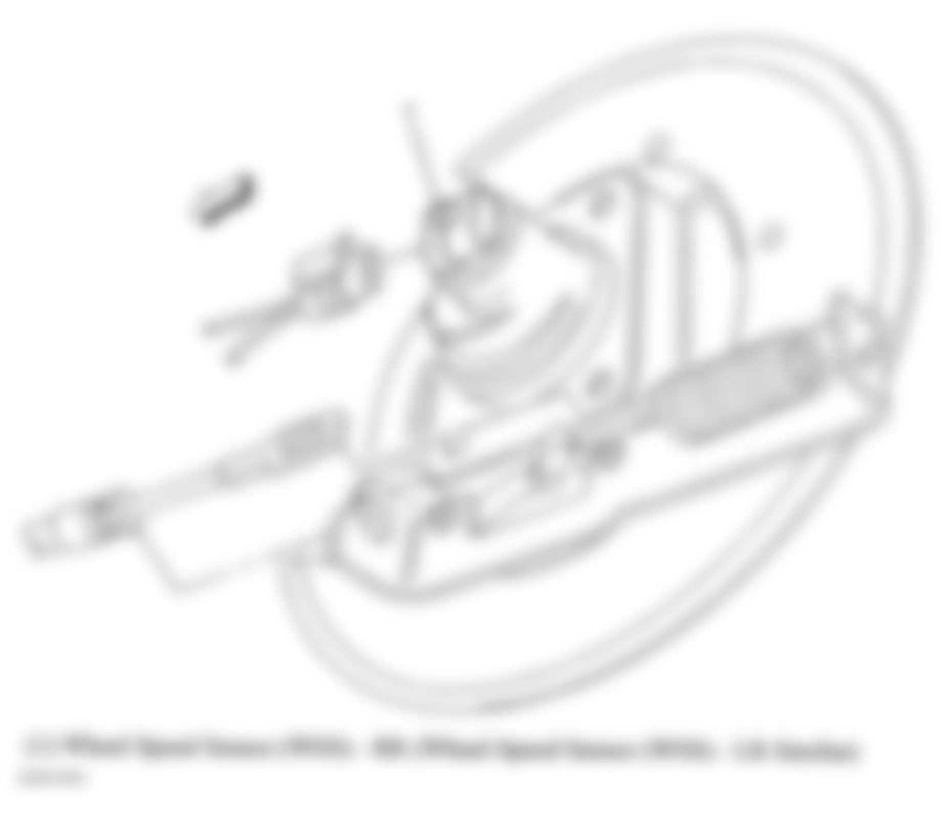
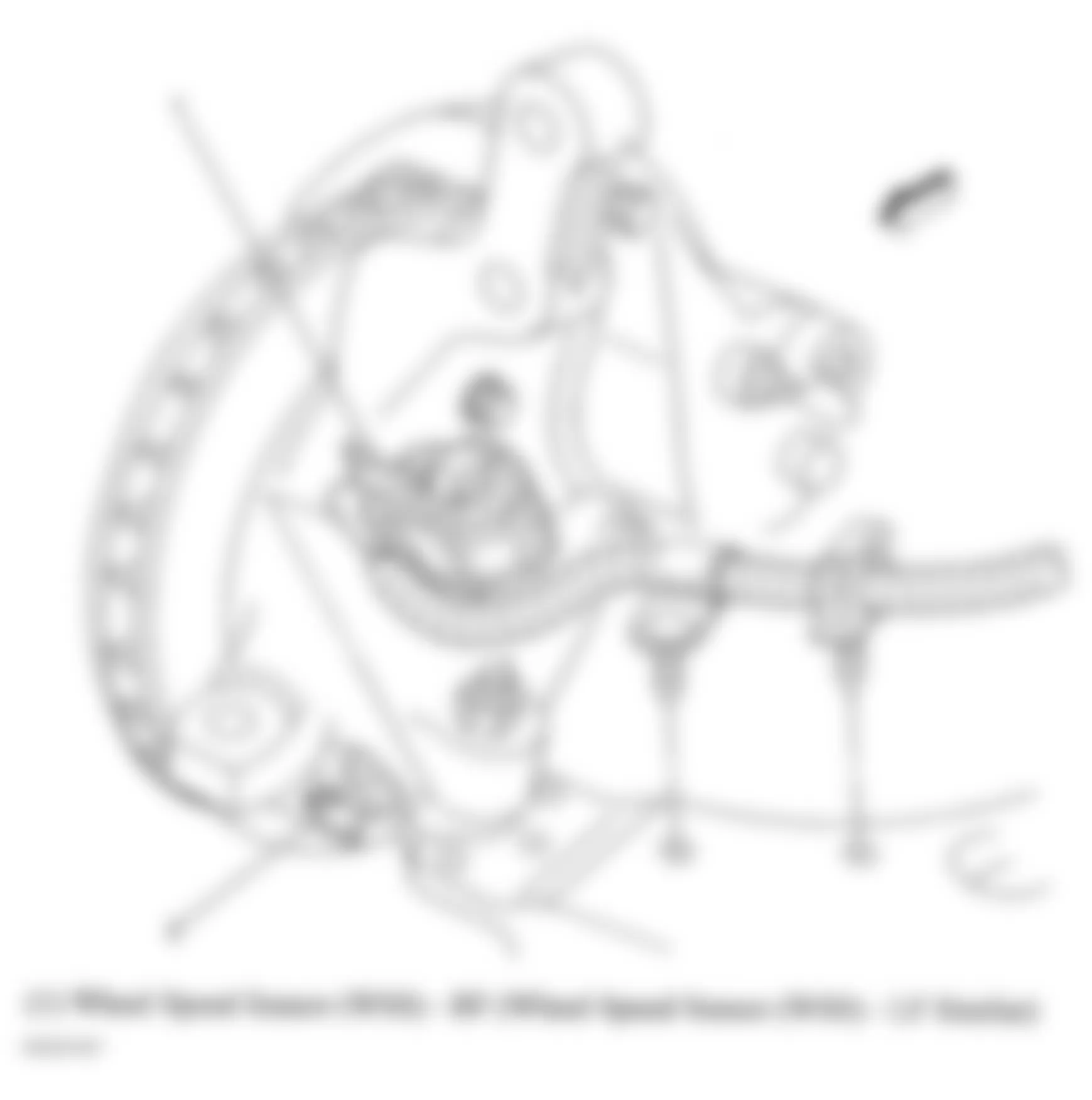
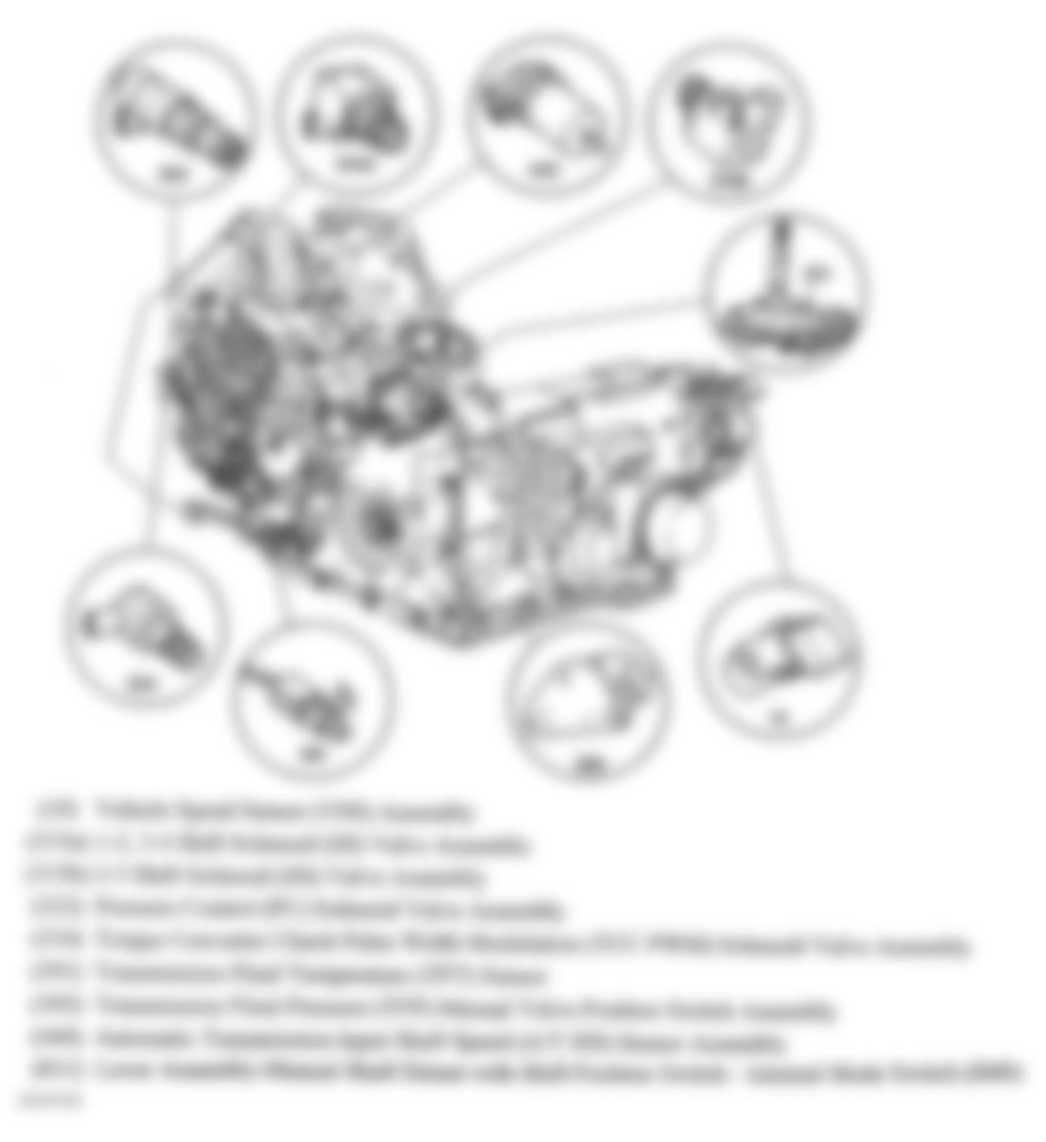
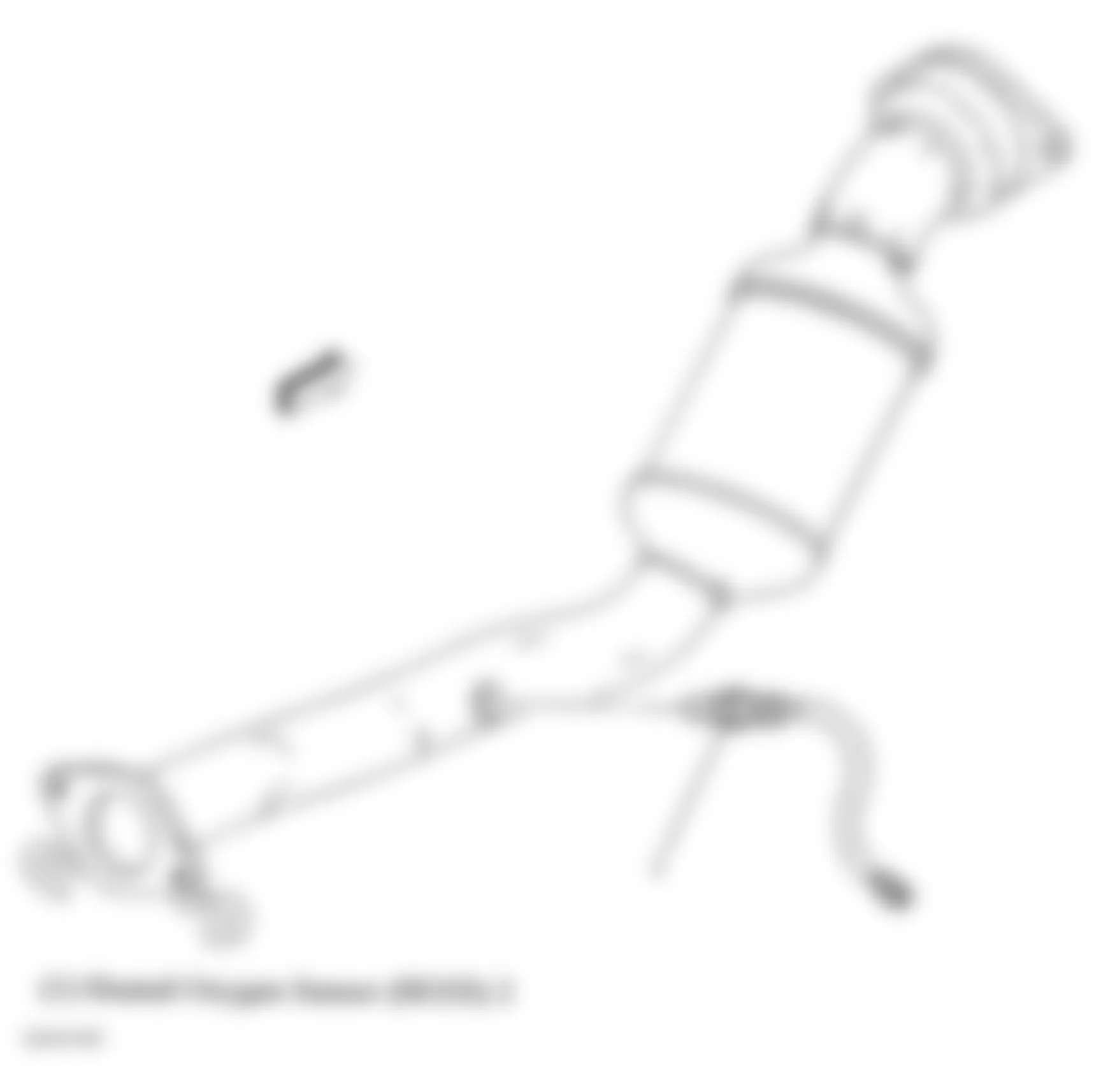
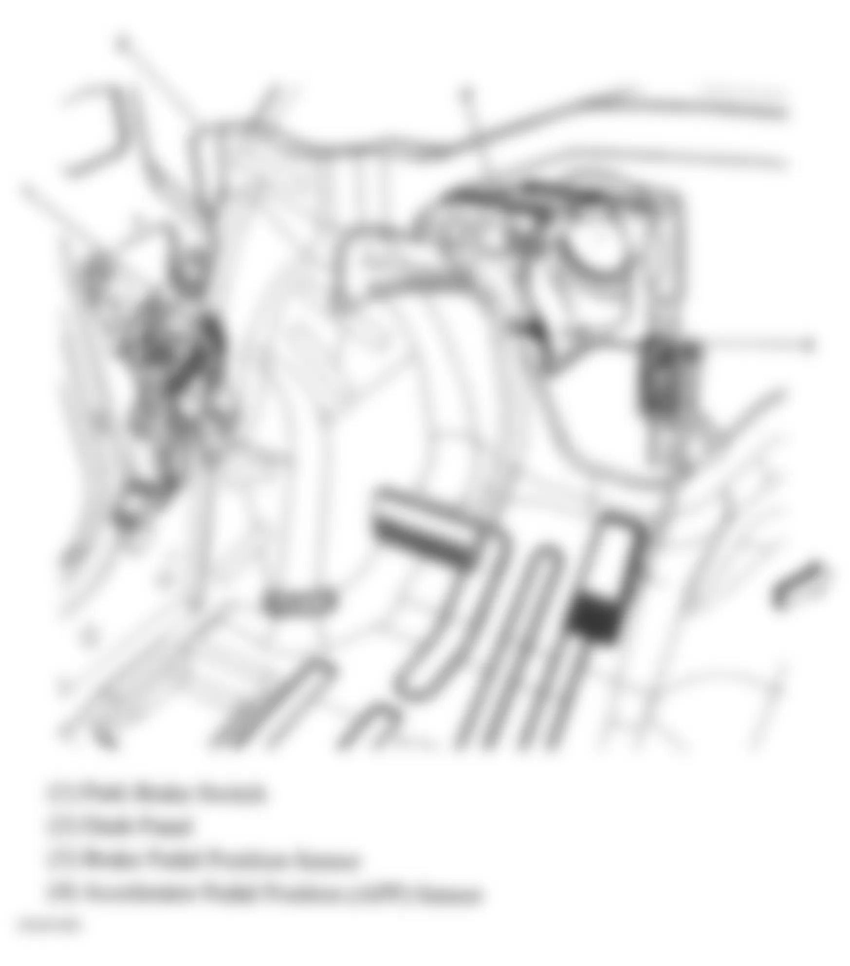
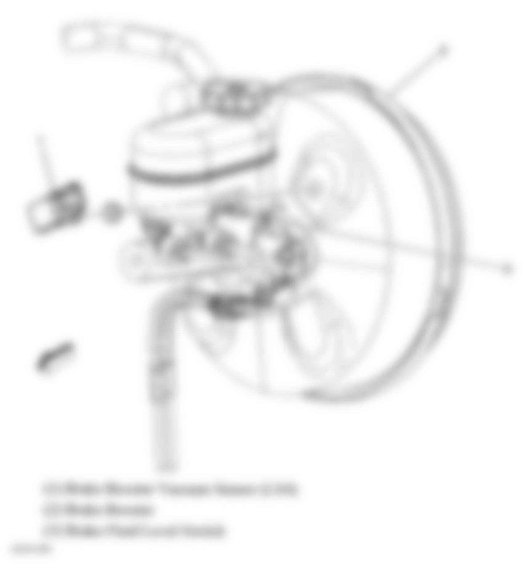
Component Location Accelerator Pedal Position (APP) Sensor Above accelerator pedal. See Fig. 24. A/C Refrigerant Pressure Sensor Under air cleaner. See Fig. 1. Ambient Air Temperature Sensor In front of radiator. See Fig. 43. Ambient Light Sensor Top center of dash. See Fig. 37. Automatic Transmission Fluid Temperature (TFT) Sensor Inside automatic transaxle. Automatic Transmission Input Shaft Speed (A/T ISS) Sensor Inside automatic transaxle. See Fig. 4. Battery Current Sensor On positive battery cable. See Fig. 35. Brake Booster Vacuum Sensor At brake booster. See Fig. 42. Brake Pedal Position Sensor Right side of brake pedal bracket. See Fig. 24. Camshaft Position (CMP) Sensor (3.5L & 3.9L) Center of engine block above timing cover. See Fig. 22. Camshaft Position (CMP) Sensor (5.3L) In timing cover, to left of water pump pulley. See Fig. 27. Crankshaft Position (CKP) Sensor (3.5L & 3.9L) Above transaxle. Crankshaft Position (CKP) Sensor (5.3L) At end of crankshaft, behind harmonic balancer. See Fig. 29. Engine Coolant Temperature (ECT) Sensor (3.5L & 3.9L) Left side of front cylinder head. See Fig. 21. Engine Coolant Temperature (ECT) Sensor (5.3L) Left front of engine at cylinder No. 1. See Fig. 27. Engine Oil Pressure (EOP) Sensor (3.5L, 3.9L) Right of starter. See Fig. 19. Engine Oil Pressure (EOP) Sensor (5.3L) Below throttle body. See Fig. 28. Fuel Level Sensor In fuel pump & sender assembly. See Fig. 30. Fuel Tank Pressure (FTP) Sensor Inside fuel tank, part of fuel pump/sender assembly. See Fig. 30. Heated Oxygen Sensor (HO2S) 1 Rear of engine, mounted in exhaust manifold. See Fig. 20. Heated Oxygen Sensor (HO2S) 1 (5.3L) Rear of engine, mounted in exhaust manifold. See Fig. 29. Heated Oxygen Sensor (HO2S) 2 In exhaust system, behind catalytic converter. See Fig. 23. Inflatable Restraint Front End Sensor - Left Front left of car, rear of front fascia, left of hood latch. See Fig. 1. Inflatable Restraint Front End Sensor - Right Front right of car, rear of front fascia, right of hood latch. See Fig. 34. Inflatable Restraint Front Passenger Presence System (PPS) Sensor In front passenger seat cushion. See Fig. 50. Inflatable Restraint Side Impact Sensor (SIS) (Left) In driver door. See Fig. 12. Inflatable Restraint Side Impact Sensor (SIS) (Right) In front passenger door. See Fig. 14. Knock Sensor (KS) Bank 1 (3.5L & 3.9L) Rear of engine, below exhaust manifold. See Fig. 22. Knock Sensor (KS) Bank 1 (5.3L) Lower left rear of engine block. See Fig. 27. Knock Sensor (KS) Bank 2 (3.5L & 3.9L) Rear of engine, below exhaust manifold. See Fig. 19. Knock Sensor (KS) Bank 2 (5.3L) Rear of engine, below exhaust manifold. See Fig. 29. Manifold Absolute Pressure (MAP) Sensor (3.5L & 3.9L) Behind throttle body. See Fig. 20. Manifold Absolute Pressure (MAP) Sensor (5.3L) On throttle body. See Fig. 27. Mass Air Flow (MAF)/Intake Air Temperature (IAT) Sensor In air cleaner duct. See Fig. 26. Seat Belt Tension Sensor - Passenger Part of buckle assembly. See Fig. 50. Tire Pressure Monitor Sensor - LF Inside left front tire at valve stem. See Fig. 60. Tire Pressure Monitor Sensor - LR Inside left rear tire at valve stem. See Fig. 60. Tire Pressure Monitor Sensor - RF Inside right front tire at valve stem. See Fig. 60. Tire Pressure Monitor Sensor - RR Inside right rear tire at valve stem. See Fig. 60. Transmission Fluid Temperature (TFT) Sensor On transmission assembly. See Fig. 4. Vehicle Speed Sensor (VSS) Right side of transaxle, near right axle shaft. See Fig. 4. Wheel Speed Sensor (WSS) - LF Inside left front wheel hub. Wheel Speed Sensor (WSS) - LR Inside left rear wheel hub. Wheel Speed Sensor (WSS) - RF Inside right front wheel hub. See Fig. 3. Wheel Speed Sensor (WSS) - RR Inside right rear wheel hub. See Fig. 2.
Chevrolet Monte Carlo SS 2006 - SOLENOIDS & SOLENOID VALVES
Chevrolet Monte Carlo SS 2006 SOLENOIDS & SOLENOID VALVES LOCATION
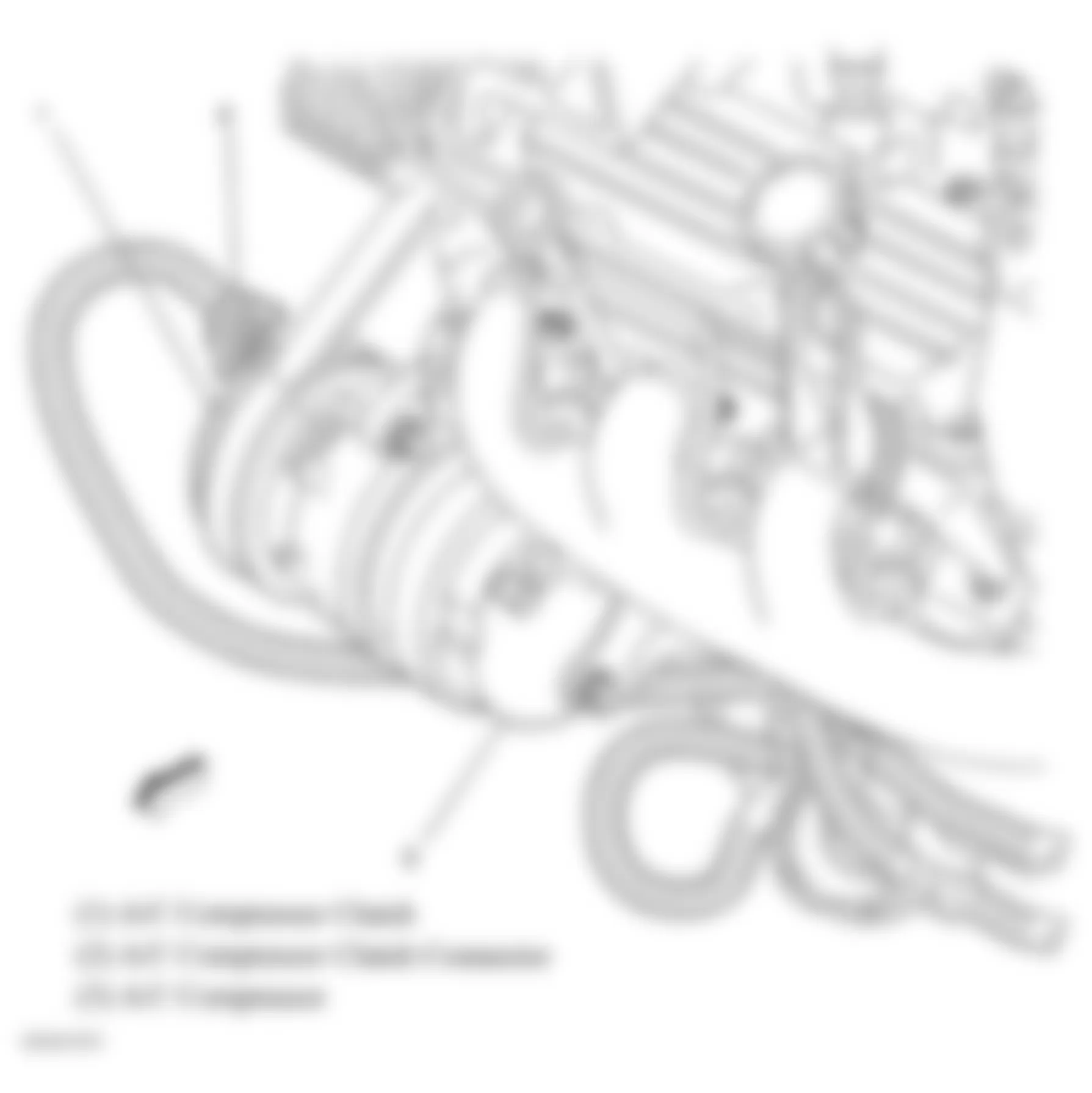
Component Location A/C Compressor Clutch Part of A/C compressor, on lower right front of engine. See Fig. 40. A/T Shift Lock Control Solenoid (W/ Floor Shifter) Under center console. See Fig. 58. A/T Shift Lock Control Solenoid (W/O Floor Shifter) Attached to right side of steering column. See Fig. 57. Camshaft Position Actuator Solenoid Top front of engine. See Fig. 19Fig. 20 . Evaporative Emission (EVAP) Canister Purge Solenoid Valve (3.5L & 3.9L) Left front of engine, in front of throttle body. See Fig. 18. Evaporative Emission (EVAP) Canister Purge Solenoid Valve (5.3L) On intake manifold, near fuel injectors. See Fig. 28. Evaporative Emission (EVAP) Canister Vent Solenoid Behind left rear wheelhouse. See Fig. 25. Fuel Injector 1 (3.5L & 3.9L) Top of engine, at number 1 cylinder intake port. See Fig. 21. Fuel Injector 1 (5.3L) Top of engine, at number 1 cylinder intake port. See Fig. 21. Fuel Injector 2 (3.5L & 3.9L) Top of engine, at number 2 cylinder intake port. See Fig. 21. Fuel Injector 2 (5.3L) Top of engine, at number 2 cylinder intake port. See Fig. 28. Fuel Injector 3 (3.5L & 3.9L) Top of engine, at number 3 cylinder intake port. See Fig. 21. Fuel Injector 3 (5.3L) Top of engine, at number 3 cylinder intake port. See Fig. 28. Fuel Injector 4 (3.5L & 3.9L) Top of engine, at number 4 cylinder intake port. See Fig. 21. Fuel Injector 4 (5.3L) Top of engine, at number 4 cylinder intake port. See Fig. 28. Fuel Injector 5 (3.5L & 3.9L) Top of engine, at number 5 cylinder intake port. See Fig. 21. Fuel Injector 5 (5.3L) Top of engine, at number 5 cylinder intake port. See Fig. 28. Fuel Injector 6 (3.5L & 3.9L) Top of engine, at number 6 cylinder intake port. See Fig. 21. Fuel Injector 6 (5.3L) Top of engine, at number 6 cylinder intake port. See Fig. 28. Fuel Injector 7 (5.3L) Top of engine, at number 7 cylinder intake port. See Fig. 28. Fuel Injector 8 (5.3L) Top of engine, at number 8 cylinder intake port. See Fig. 28. Intake Manifold Tuning (IMT) Valve Solenoid Right side of engine in intake manifold. See Fig. 20. Pressure Control (PC) Solenoid Valve Inside automatic transaxle. See Fig. 4. Starter Solenoid Left rear of engine. See Fig. 33. Torque Converter Clutch Pulse Width Modulation (TCC PWM) Solenoid Valve Assembly Inside automatic transaxle. See Fig. 4. 1-2, 3-4 Shift Solenoid (1-2) (SS) Valve Inside automatic transaxle. See Fig. 4. 2-3 Shift Solenoid (2-3) (SS) Valve Inside automatic transaxle. See Fig. 4.
Chevrolet Monte Carlo SS 2006 - SWITCHES
Chevrolet Monte Carlo SS 2006 SWITCHES LOCATION
Component Location A/C Pressure Switch On A/C line, lower left front of engine compartment. See Fig. 1. Automatic Transmission Fluid Pressure (TFP) Manual Valve Position Switch Inside automatic transaxle. Brake Fluid Level Switch Mounted under center of brake fluid reservoir. See Fig. 42. Engine Oil Level Switch (3.5L & 3.9L) Front lower center of engine oil pan. See Fig. 22. Engine Oil Level Switch (5.3L) Bottom of oil pan. See Fig. 29. Hood Ajar Switch Part of hood latch. See Fig. 43. Park Brake Switch Part of park brake assembly. See Fig. 24. Rear Compartment Lid Ajar Switch On deck lid. See Fig. 6. Seat Belt Switch - Driver Inside driver seat belt buckle. See Fig. 55. Seat Belt Switch - Passenger Inside front passenger seat belt buckle. See Fig. 50. Transmission Fluid Pressure (TFT) Manual Valve Position Switch Assembly On transmission assembly. See Fig. 4. Transmission Internal Mode Switch (IMS) Inside automatic transaxle. Turn Signal/Multifunction Switch Inside steering column, below inflatable restraint steering wheel module coil. See Fig. 37. Windshield Washer Fluid Level Switch In lower portion of washer fluid container. See Fig. 34.
Chevrolet Monte Carlo SS 2006 - MISCELLANEOUS
Chevrolet Monte Carlo SS 2006 MISCELLANEOUS LOCATION
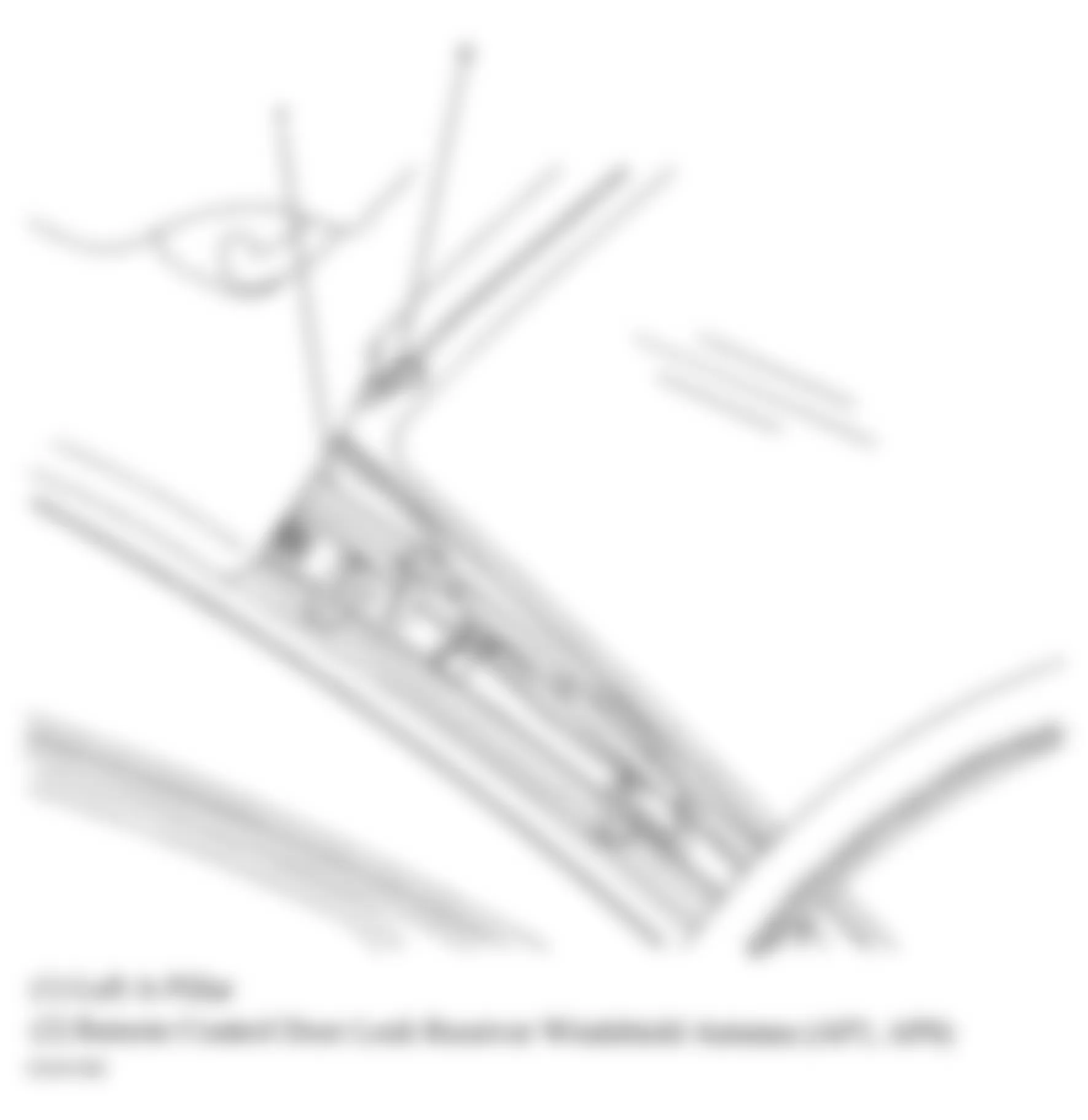
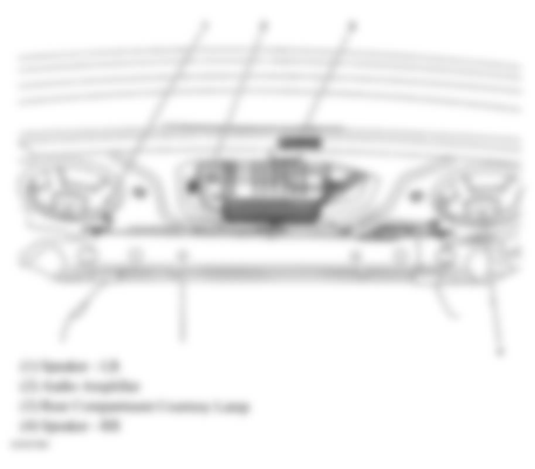
Component Location A/C Compressor Clutch Diode In wiring harness, 10 cm from A/C compressor clutch. Audio Amplifier Center of rear compartment. See Fig. 47. Cellular Navigation & Digital Radio Antenna Top rear center of roof. See Fig. 7. Data Link Connector (DLC) Left of steering column. See Fig. 10. Digital Radio Receiver Mounted to rear of right rear wheelwell. See Fig. 39. Door Lock - Driver (Sedan) Rear of driver door. Door Lock - Front Passenger (Sedan) Rear of passenger door. Door Lock - LR (Sedan) Rear of left rear door. Door Lock - RR (Sedan) Rear of right rear door. Generator Top right rear side of engine. See Fig. 34. Heated Seat Element - Driver (Seat Back) Under upholstery of driver seat back. See Fig. 56. Heated Seat Element - Driver (Seat Bottom) Under upholstery of driver seat bottom. See Fig. 56. Heated Seat Element - Passenger (Seat Back) Under upholstery of passenger seat back. Heated Seat Element - Passenger (Seat Bottom) Under upholstery of passenger seat bottom. See Fig. 50. Horn Assembly Below right headlamp. See Fig. 34. Ignition Coil 1 (3.5L & 3.9L) Top of engine, at number 1 cylinder. See Fig. 27. Ignition Coil 1 (5.3L) Top of engine, at number 1 cylinder. See Fig. 28. Ignition Coil 2 (3.5L & 3.9L) Top of engine, at number 2 cylinder. See Fig. 27. Ignition Coil 2 (5.3L) Top of engine, at number 2 cylinder. See Fig. 28. Ignition Coil 3 (3.5L & 3.9L) Top of engine, at number 3 cylinder. See Fig. 27. Ignition Coil 3 (5.3L) Top of engine, at number 3 cylinder. See Fig. 28. Ignition Coil 4 (3.5L & 3.9L) Top of engine, at number 4 cylinder. See Fig. 27. Ignition Coil 4 (5.3L) Top of engine, at number 4 cylinder. See Fig. 28. Ignition Coil 5 (3.5L & 3.9L) Top of engine, at number 5 cylinder. See Fig. 27. Ignition Coil 5 (5.3L) Top of engine, at number 5 cylinder. See Fig. 28. Ignition Coil 6 (3.5L & 3.9L) Top of engine, at number 6 cylinder. See Fig. 27. Ignition Coil 6 (5.3L) Top of engine, at number 6 cylinder. See Fig. 28. Ignition Coil 7 (5.3L) Top of engine, at number 7 cylinder. See Fig. 28. Ignition Coil 8 (5.3L) Top of engine, at number 8 cylinder. See Fig. 28. Inflatable Restraint Steering Wheel Module Coil In steering column behind steering wheel. Radio Center of dash. See Fig. 36. Remote Control Door Lock Receiver Windshield Antenna Left "A" pillar. See Fig. 44. Seat Belt Pretensioner - Left At base of "B" pillar. See Fig. 49. Seat Belt Pretensioner - Right At base of "B" pillar. See Fig. 52. Valve Lifter Oil Manifold Assembly Under throttle actuator control (TAC) module.
Chevrolet Monte Carlo SS 2006 - CONNECTORS
Chevrolet Monte Carlo SS 2006 CONNECTORS LOCATION
Component Location C100 (20 Pin) In engine wiring harness to automatic transaxle wiring harness, on top of transmission. See Fig. 33. C101 (Black, 10 Pin) In I/P wiring harness to engine wiring harness, bolted to left strut tower next to C111. See Fig. 62. C102 (Black, 16 Pin) In engine wiring harness to fuel injector wiring harness, top right side of engine. See Fig. 75. C105 (Black, 2 Pin) In I/P wiring harness to battery cable harness, forward of right front strut tower. See Fig. 71. C107 (Blue/Gray, 8 Pin) In engine wiring harness to ignition control module wiring harness, on top of engine between fuel injectors 3 / 5. See Fig. 73. C108 (Blue/Gray, 8 Pin) In engine wiring harness to ignition control module wiring harness, on top of engine between fuel injectors 4 & 6. See Fig. 62. C111 (Black, 14 Pin) In I/P wiring harness to engine wiring harness, bolted to left strut tower next to C101. See Fig. 62. C116 (Black, 5 Pin) In engine wiring harness to crank sensor jumper harness, on transmission. See Fig. 73. C120 (Black, 10 Pin) In I/P wiring harness to forward lamp wiring harness, behind left headlamp assembly on frame. See Fig. 70. C122 (Black, 6 Pin) In forward lamp wiring harness to forward lamp wiring harness, at left side of right headlamp assembly. See Fig. 70. C123 (Black, 4 Pin) In I/P wiring harness to grill lamp jumper harness, forward of RF strut tower. See Fig. 63. C141 (Black, 5 Pin) In forward lamp wiring harness to left headlamp harness, behind left headlamp assembly. See Fig. 70. C142 (Black, 5 Pin) In forward lamp wiring harness to right headlamp harness, behind right headlamp assembly. See Fig. 70. C200 (Blue/Gray, 40 Pin) In body wiring harness to I/P wiring harness, below I/P fuse panel. See Fig. 10. C201 (Black, 10 Pin) In steering column harness to I/P wiring harness, behind knee bolster to right of steering column. See Fig. 10. C203 (Blue/Gray, 22 Pin) In body wiring harness to I/P wiring harness, near C250. See Fig. 11. C208 (Black, 2 Pin) In SEO auxiliary wiring harness to body harness, at right front footwell. C210 (Black, 2 Pin) In I/P wiring harness to HVAC harness, on right side of HVAC module assembly. See Fig. 10. C223 (Black, 2 Pin) In body wiring harness, near G301. C250 (Yellow, 4 Pin) In inflatable restraint steering wheel module coil wiring harness to body wiring harness, near C203,. See Fig. 11. C266A (Black, 1 Pin) In I/P wiring harness to C266B, above right front footwell. See Fig. 10. C266B (Black, 1 Pin) In I/P wiring harness to C266A, above right front footwell. See Fig. 10. C267A (Blue, 8 Pin) In I/P wiring harness to C267B, above right front footwell. See Fig. 10. C267B (Blue, 8 Pin) In I/P wiring harness to C267A, above right front footwell. See Fig. 10. C275 (Black, 8 Pin) In Inflatable restraint steering wheel module coil wiring harness to steering column wiring harness, taped to steering column harness. C277 (Black, 8 Pin) In inflatable restraint steering wheel module coil wiring harness to steering wheel wiring harness, behind inflatable restraint steering wheel module. See Fig. 76. C278 (Yellow, 4 Pin) In inflatable restraint I/P module jumper harness to body harness, behind right I/P access panel. C297 (Blue/Gray, 6 Pin) In I/P wiring harness to emergency vehicle front lamps flasher harness, above right front footwell. See Fig. 10. C301 (Gray, 40 Pin) In body wiring harness to left front door wiring harness, between door hinges. See Fig. 77. C302 (Gray, 40 Pin) In body wiring harness to right front door wiring harness, between door hinges. See Fig. 77. C303 (1 Pin) In I/P wiring harness to body wiring harness COAX connector, next to G302. See Fig. 66. C311 (Black, 12 Pin) In body wiring harness to driver seat wiring harness, below driver seat. See Fig. 77. C312 (Yellow, 2 Pin) In left inflatable restraint side impact module jumper harness to body harness, below drivers seat. See Fig. 53. C313 (Black, 12 Pin) In body wiring harness to front passenger seat wiring harness, below front passenger seat. See Fig. 77. C314 (Yellow, 2 Pin) In right inflatable restraint side impact module jumper harness to body harness, below passenger seat. See Fig. 53. C322 (Black, 2 Pin) In body wiring harness to roof wiring provisions harness, near right "C" pillar. See Fig. 80. C340 (Coupe) (Black, 2 Pin) In body wiring harness to floor console wiring harness, below center floor console. C340 (Sedan) (Black, 2 Pin) In body wiring harness to auxiliary power outlet seat jumper harness, under center of front seat. See Fig. 77. C355 (Black/Gray, 9 Pin) In body wiring harness to left rear door wiring harness, center of left rear door jamb. See Fig. 84. C356 (Black/Gray, 9 Pin) In body wiring harness to right rear door wiring harness, center of right rear door jamb. See Fig. 85. C360 (Black, 1 Pin) In body harness to I/P harness, near C200. See Fig. 10. C362 (Black, 1 Pin) In body harness to I/P harness, near C200. See Fig. 10. C398 (Black, 6 Pin) In sunroof wiring harness to roof wiring harness, above sunshade. See Fig. 67. C401 (Gray, 4 Pin) In rear body harness to left tail lamp harness, near left tail lamp assembly. See Fig. 88. C402 (Gray, 4 Pin) In rear body harness to right tail lamp harness, near right tail lamp assembly. See Fig. 88. C405 (Gray, 12 Pin) In rear chassis harness to body harness, forward of right of spare tire well. See Fig. 81. C406 (Black, 8 Pin) In body harness to rear body harness, clipped on bumper fascia. See Fig. 81. C409 (Black, 2 Pin) In emergency vehicle rear compartment lid lamps wiring harness to body wiring harness, between center high mounted stop lamp (CHMSL) & rear junction block. See Fig. 48. C412 (Yellow, 2 Pin) In left roof rail module left jumper harness to body harness, behind left "C" pillar trim. See Fig. 79. C414 (Yellow, 2 Pin) In right roof rail module jumper harness to body harness, behind right "C" pillar trim. See Fig. 79. C430 (Coupe) (Black, 4 Pin) In rear compartment lid harness to body harness, above right rear wheelhouse. See Fig. 87. C490 (Coupe) (Gray, 18 Pin) In body wiring harness to roof wiring harness, behind left "C" pillar trim. See Fig. 67. C490 (Sedan) (Black, 18 Pin) In body wiring harness to roof wiring harness, under left side of rear package shelf trim panel. See Fig. 81. C503 (Sedan) (Gray, 40 Pin) In driver door wiring harness to driver door trim wiring harness, near left front door speaker. See Fig. 82. C604 (Sedan) (Black, 10 Pin) In front passenger door trim wiring harness to front passenger door harness, near right front door speaker. See Fig. 83.
Chevrolet Monte Carlo SS 2006 - GROUNDS
Chevrolet Monte Carlo SS 2006 GROUNDS LOCATION
Component Location G100 Behind right headlamp, on frame. See Fig. 70. G101 Behind left headlamp, on frame. See Fig. 70. G102 Near battery. See Fig. 34. G111 (3.5L & 3.9L) On transmission to engine bolt, above starter. See Fig. 61. G111 (5.3L) On transmission to engine bolt, below starter. See Fig. 62. G113 On front of automatic transaxle, left of G111. See Fig. 62. G115 (3.5L & 3.9L) On transmission case, below brake booster. See Fig. 75. G115 (5.3L) Lower front of engine, under cylinder #5 exhaust port. See Fig. 62. G200 Front of dash, left of G204. See Fig. 10. G201 Front of dash, above G202. See Fig. 10. G202 On right side of steering column below C201. See Fig. 10. G204 Right side of dash, next to G200. See Fig. 10. G301 Below driver door opening, rear of left A-pillar. See Fig. 65. G302 Below passenger front door opening, rear of right A-pillar. See Fig. 66. G403 (Coupe) In rear compartment, near left "C" pillar. See Fig. 67. G403 (Sedan) On left side of package shelf, near "C pillar. See Fig. 78. G404 (Coupe) On right "C" pillar, near connector C430. See Fig. 68. G404 (Sedan) On right side of package shelf, near "C" pillar. See Fig. 78.
Chevrolet Monte Carlo SS 2006 - SPLICES
Chevrolet Monte Carlo SS 2006 SPLICES LOCATION
Component Location Splice Pack SP205 Clipped to inner I/P structure, to right of steering column. See Fig. 10. Splice Pack SP206 On I/P harness, near steering column. Splice Pack SP207 On I/P harness, near steering column. S101 (3.5L & 3.9L) In engine wiring harness, approximately 7 cm (2.75 in) from breakout to G113. S101 (5.3L) In engine wiring harness, approximately 5 cm (2 in) from breakout to G112. See Fig. 62. S105 In engine wiring harness, approximately 5.5 cm (2.25 in) from breakout to starter. See Fig. 75. S105 (3.5L & 3.9L) In engine wiring harness, approximately 5 cm (2.0 in) from breakout towards starter. See Fig. 74. S106 On ignition control module wiring harness. S107 On ignition control module wiring harness. S108 In engine wiring harness, approximately 5 cm (2 in) from breakout to fuel injector 3. See Fig. 73. S109 (3.5L & 3.9L) On fuel injector wiring harness. S109 (5.3L) In engine wiring harness, approximately 5 cm (2 in) from breakout to fuel injector 4. See Fig. 72. S115 In automatic transaxle wiring harness, approximately 9.5 cm (3.8 in) from connector C100. S124 On forward lamp wiring harness, approximately 8 cm (3.2 in) from breakout to G100. See Fig. 70. S126 On right head lamp assembly wiring harness. S127 On left head lamp assembly wiring harness. S128 On right headlamp harness. S129 On left headlamp harness. S130 On ignition control module wiring harness. S131 On ignition control module wiring harness. S132 On ignition control module wiring harness. S133 On ignition control module wiring harness. S203 (Except Police) On I/P wiring harness, approximately 11.5 cm (4.5 in) from second breakout to brake pedal position sensor. See Fig. 64. S203 (Police) On I/P wiring harness, approximately 30.5 cm (12.5 in) from third breakout to brake pedal position sensor. See Fig. 64. S204 On steering column harness, between BCM connector C1 & ignition switch. S212 On steering wheel harness. S213 On steering wheel harness, behind inflatable restraint steering wheel module. S214 On steering column harness, between C201 & turn signal/multifunction switch. S215 In steering wheel harness, behind inflatable restraint steering wheel module. S218 On I/P wiring harness approximately 20 cm (8 in) from breakout to remote control door lock receiver. See Fig. 64. S228 (Except Police) On I/P wiring harness approximately 7.5 cm (3 in) from breakout to brake pedal position sensor. S228 (Police) On I/P wiring harness, approximately 12.5 cm (5 in) from brake pedal position sensor towards C201. S231 (Sedan) On floor console wiring harness, approximately 12 cm (4.75 in) from breakout to auxiliary power outlet. S238 (Sedan) On floor console wiring harness, approximately 5 cm (2 in) from breakout to C340. S239 On I/P wiring harness, approximately 5 cm (2 in) from second breakout to brake pedal position sensor. See Fig. 64. S250 In I/P wiring harness, approximately 15.5 cm (6.25 in) from 3rd breakout to brake pedal position sensor. See Fig. 64. S259 (Coupe) On I/P wiring harness, approximately 5 cm (2 in) from breakout to data link connector (DLC). See Fig. 64. S259 (Sedan) On I/P wiring harness approximately 4 cm (1.5 in) from breakout to remote control door lock receiver (RCDLR) towards data link connector (DLC). See Fig. 64. S269 On I/P wiring harness, approximately 6.5 cm (2.5 in) from breakout to data link connector. See Fig. 64. S282 In I/P wiring harness, approximately 37.5 cm (15 in) from 3rd breakout to brake pedal position sensor. See Fig. 64. S303 (Coupe) In body wiring harness, approximately 8.5 cm (3.5 in) from second breakout to C311. S303 (Sedan) In body wiring harness, approximately 8.5 cm (3.5 in) from breakout to C311. See Fig. 77. S307 (Sedan) In body harness, approximately 16.5 cm (6.5 in) from breakout to C301. See Fig. 77. S308 (Coupe) In Body wiring harness, approximately 24 cm (9.5 in) from second breakout to C311. S308 (Sedan) In body wiring harness, approximately 14 cm (5.5 in) from breakout to G301. See Fig. 77. S311 (Coupe) In body wiring harness, approximately 7 cm (2.75 in) from second breakout to C302. S311 (Sedan) In body wiring harness, approximately 10 cm (4 in) from second breakout to C302. S314 (Sedan) On body wiring harness, approximately 16 cm (6.5 in) from breakout to C313. See Fig. 77. S315 (Sedan) On body wiring harness, approximately 5 cm (2 in) from breakout to C313. See Fig. 77. S324 (Coupe) On body harness, approximately 7 cm (2.75 in) from breakout to C405. See Fig. 81. S324 (Sedan) On body harness, approximately 24 cm (9.5 in) from breakout to C405. See Fig. 81. S332 (Sedan) On body harness, approximately 12 cm (4.75 in) from breakout to left seat belt pretensioner. See Fig. 77. S350 (Coupe) On body harness, approximately 18 cm (7.2 in) from second breakout to C311. S350 (Sedan) On body harness, approximately 14.5 cm (5.75 in) from breakout to G302. See Fig. 77. S359 (Sedan) On body harness, approximately 24 cm (9.5 in) from breakout to C311. See Fig. 77. S364 (Coupe) On roof harness, approximately 16.5 cm (6.5 in) from second breakout to C398. See Fig. 67. S364 (Sedan) On roof harness, approximately 10 cm (4 in) from breakout to C398. S375 (Sedan) On body harness, approximately 15 cm (6 in) from breakout to inflatable restraint sensing & diagnostic module. See Fig. 77. S376 (Sedan) On body harness, approximately 22 cm (8.75 in) from breakout to center high mounted stop lamp. S390 (Coupe) On roof wiring harness, approximately 34 cm (13.5 in) from breakout to dome lamp. See Fig. 67. S390 (Sedan) On roof wiring harness, approximately 53 cm (21 in) from breakout to dome lamp. S393 (Coupe) On roof wiring harness, approximately 19 cm (7.5 in) from breakout to dome lamp. See Fig. 67. S393 (Sedan) On roof wiring harness, approximately 38 cm (15.25 in) from breakout to dome lamp. S394 On body harness, approximately 15 cm (6 in) from breakout to inflatable restraint sensing & diagnostic module. S417 On body harness, approximately 32 cm (12.75 in) from breakout to left seat belt pretensioner. S430 (Coupe) On rear body harness, approximately 10 cm (4 in) from breakout to right backup lamp. See Fig. 89. S430 (Sedan) On rear body harness, approximately 14 cm (5.5 in) from breakout to right license lamp. S431 On right tail lamp harness. S470 On left tail lamp harness. S474 (Except Police) On body harness, approximately 17 cm (6.5 in) from breakout to C430. S474 (Police) On body harness, approximately 45.5 cm (18 in) from breakout to C409. S485 (Coupe) On rear body harness, approximately 10 cm (4 in) from breakout to license lamp. See Fig. 89. S485 (Sedan) On rear body harness, approximately 24 cm (9.5 in) from breakout to license lamp. S487 On left tail lamp harness. S488 On right tail lamp harness. S504 (Sedan) On driver door trim wiring harness, approximately 4.5 cm (1.75 in) from breakout to window switch. See Fig. 82. S505 (Coupe) On driver door wiring harness, approximately 20 cm (8 in) from breakout to driver's door lock switch. S505 (Sedan) On driver door wiring harness, approximately 18.5 cm (7.25 in) from breakout to left front door speaker. See Fig. 82. S506 (Coupe) On driver door wiring harness, approximately 3.5 cm (1.5 in) from breakout to driver's outside rearview mirror. S506 (Sedan) On driver door trim wiring harness, approximately 11 cm (4.25 in) from breakout to driver's window switch. See Fig. 82. S604 (Coupe) On front passenger door wiring harness, approximately 20 cm (8 in) from breakout to passenger's door lock switch. S604 (Sedan) On front passenger door wiring harness, approximately 6 cm (2.5 in) from breakout to right front speaker. See Fig. 83. S608 (Coupe) On front passenger door wiring harness, approximately 3.5 cm (1.5 in) from breakout to passengers outside rearview mirror. See Fig. 83. S608 (Sedan) On front passenger door trim wiring harness, approximately 6.5 cm (2.5 in) from front window switch. S901 (Coupe) On rear compartment lid wiring harness, approximately 11 cm (4.25 in) from breakout to center high mounted stop lamp. See Fig. 87. S902 In rear body harness, at decklid. See Fig. 87.
Chevrolet Monte Carlo SS 2006 - COMPONENT LOCATION GRAPHICS
NOTE:
Fig.res may show multiple component locations. - appropriate table for proper figure references.

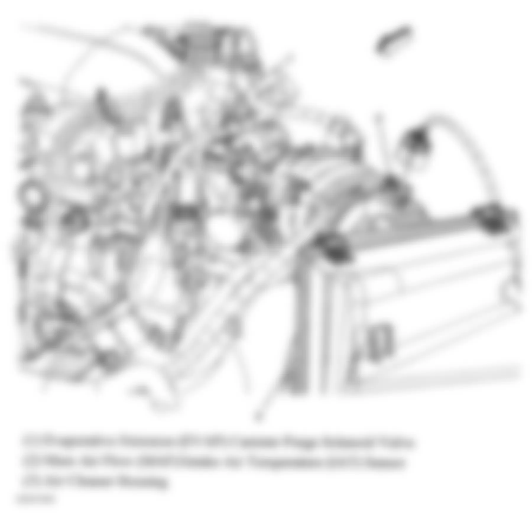
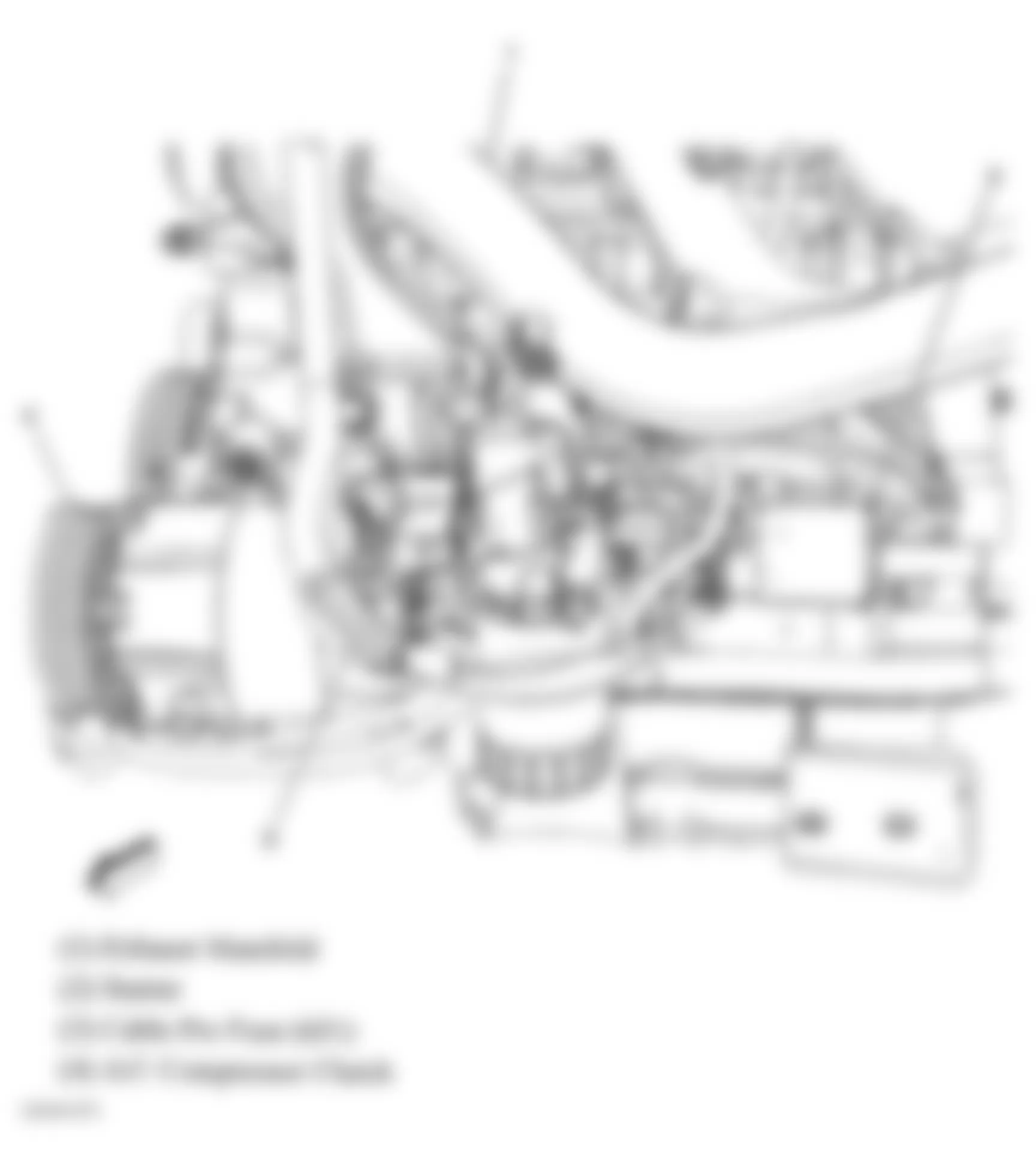
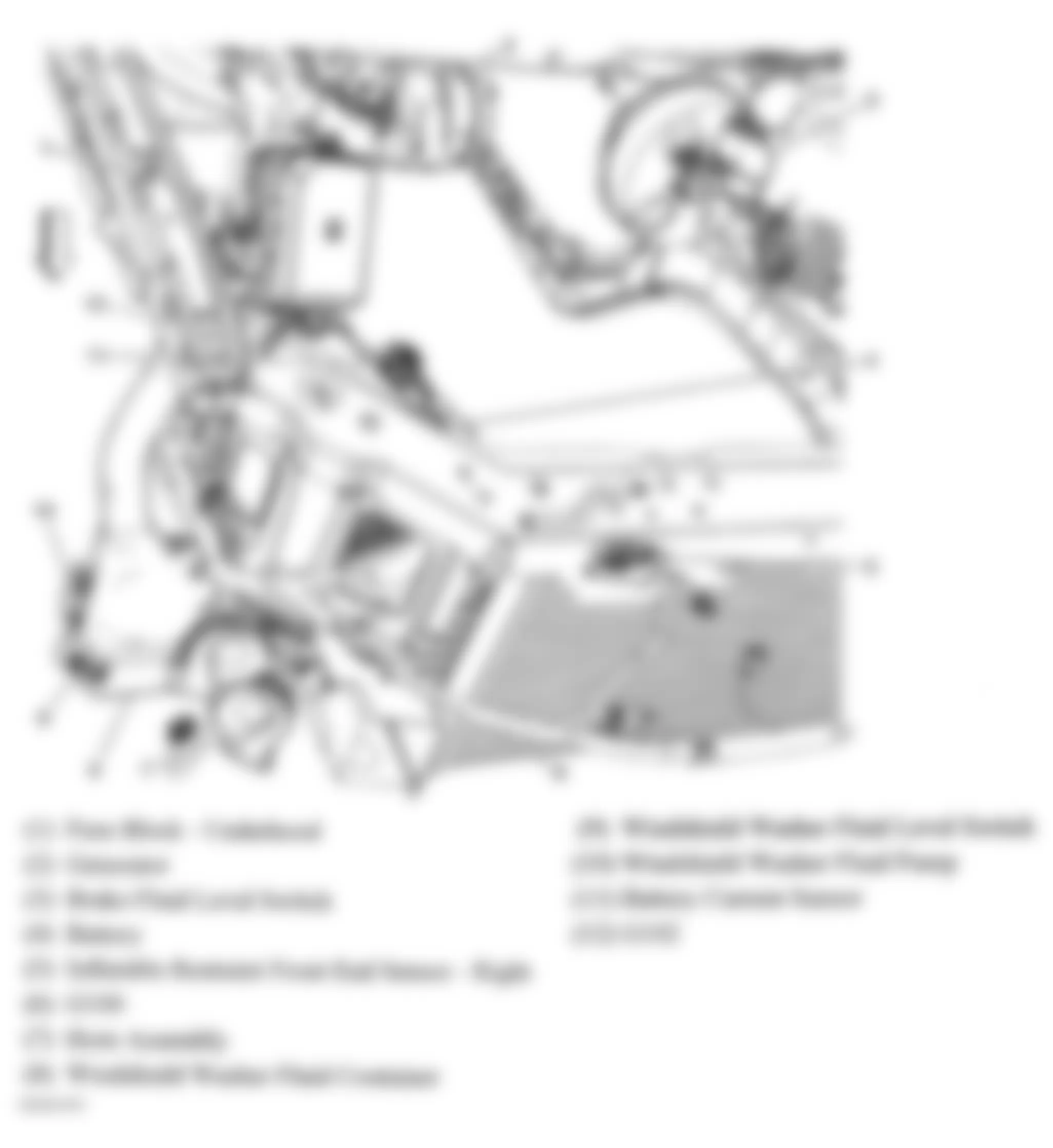
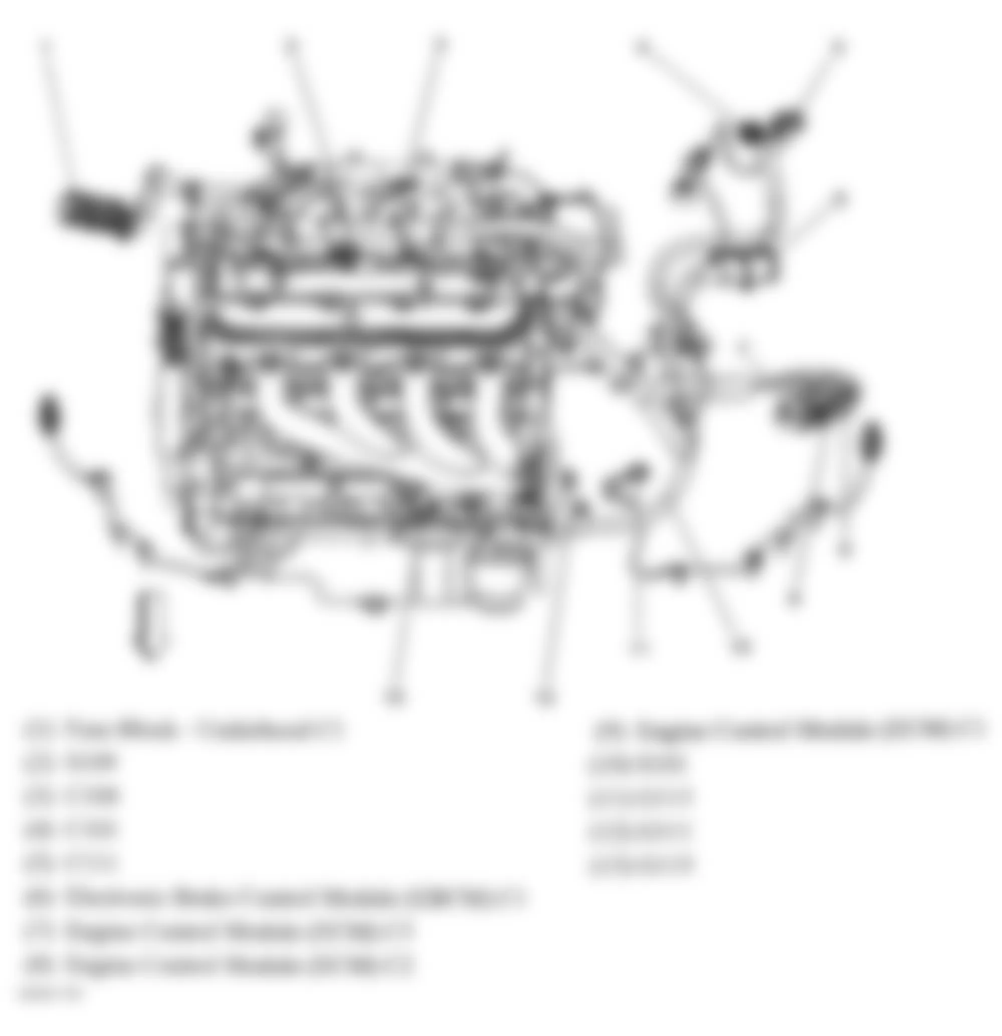
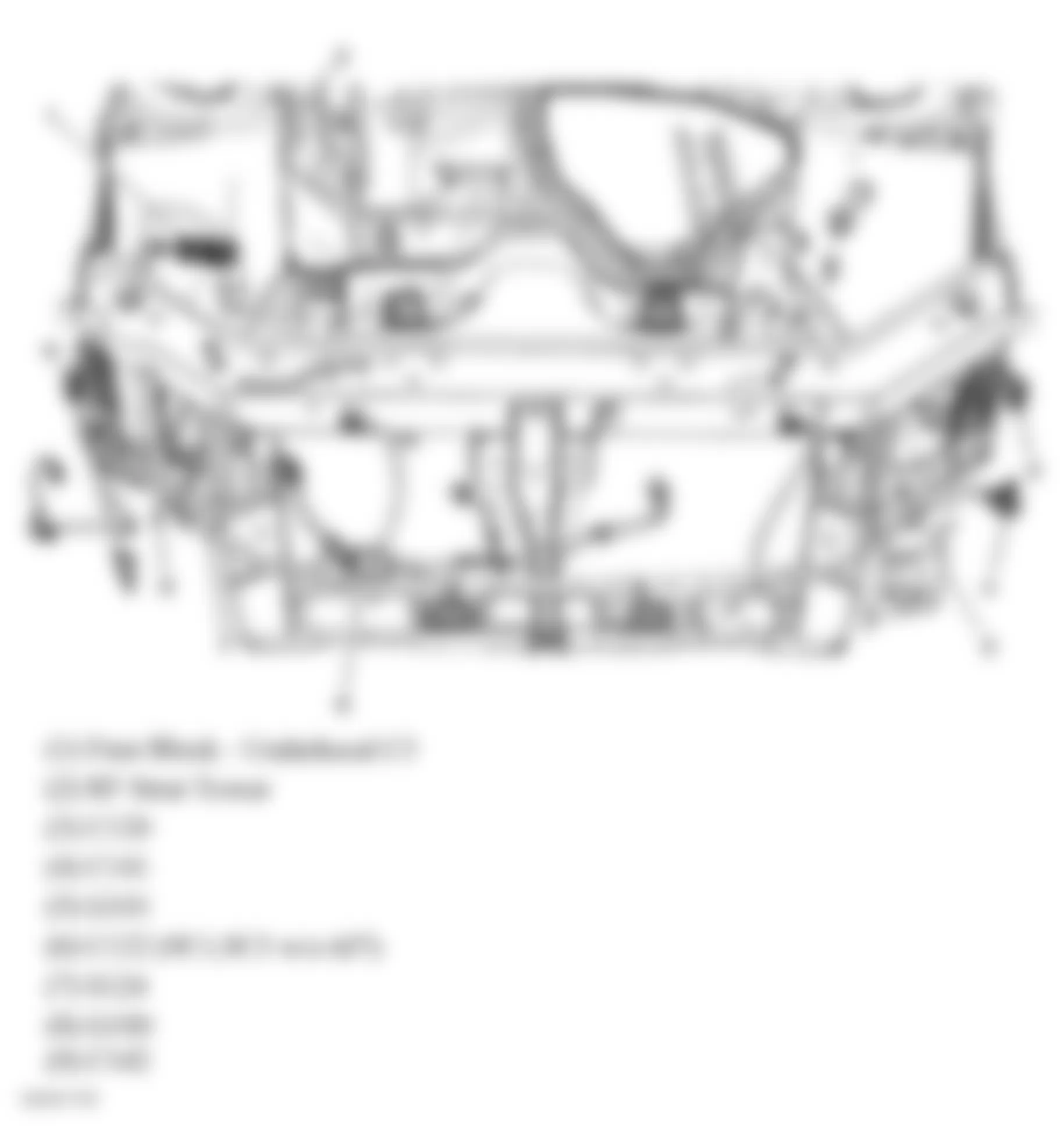
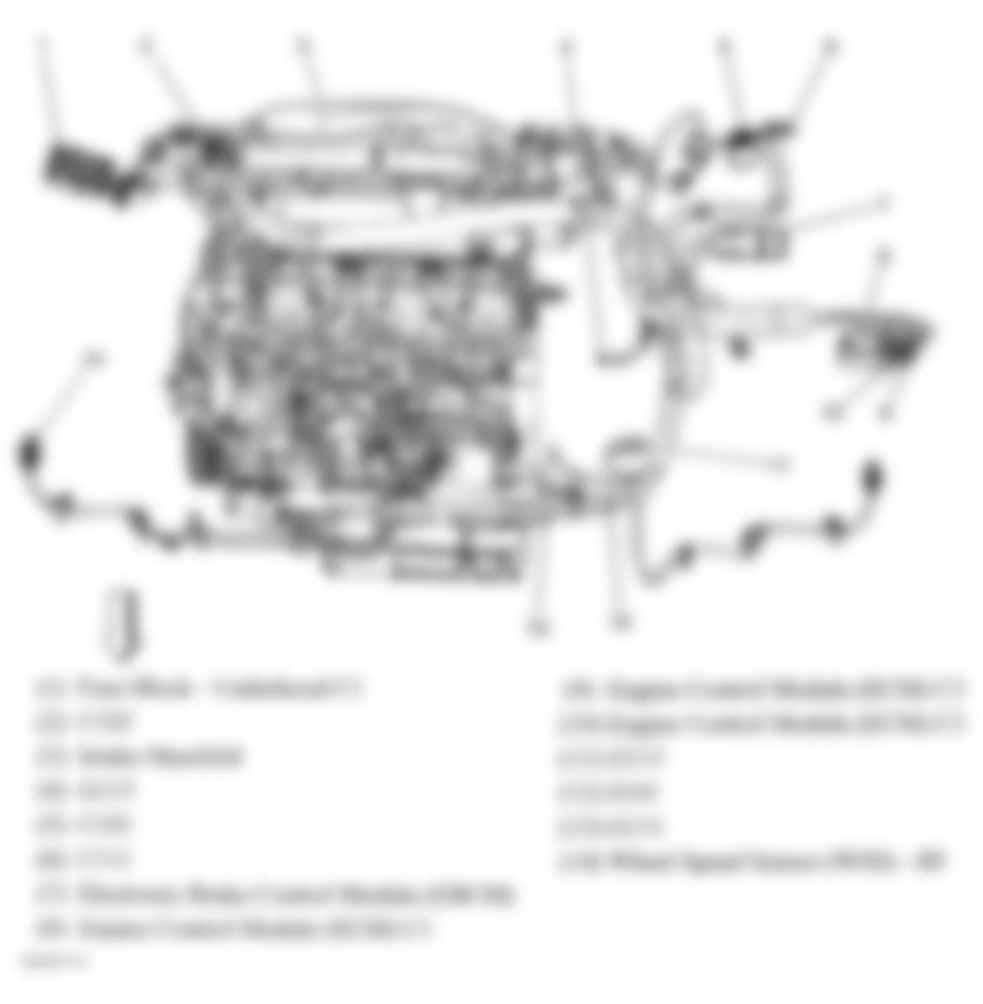
Fig. 1: Chevrolet Monte Carlo SS 2006 - Component Locations - Left Front Of Engine Compartment
Fig. 2: Chevrolet Monte Carlo SS 2006 - Component Locations - Right Rear Hub Assembly
Fig. 3: Chevrolet Monte Carlo SS 2006 - Component Locations - Right Front Hub Assembly
Fig. 4: Chevrolet Monte Carlo SS 2006 - Component Locations - Transmission Assembly
Fig. 5: Chevrolet Monte Carlo SS 2006 - Component Locations - Left Front Of Engine Compartment
Fig. 6: Chevrolet Monte Carlo SS 2006 - Component Locations - Body Rear End Component Views
Fig. 7: Chevrolet Monte Carlo SS 2006 - Component Locations - Headliner Components
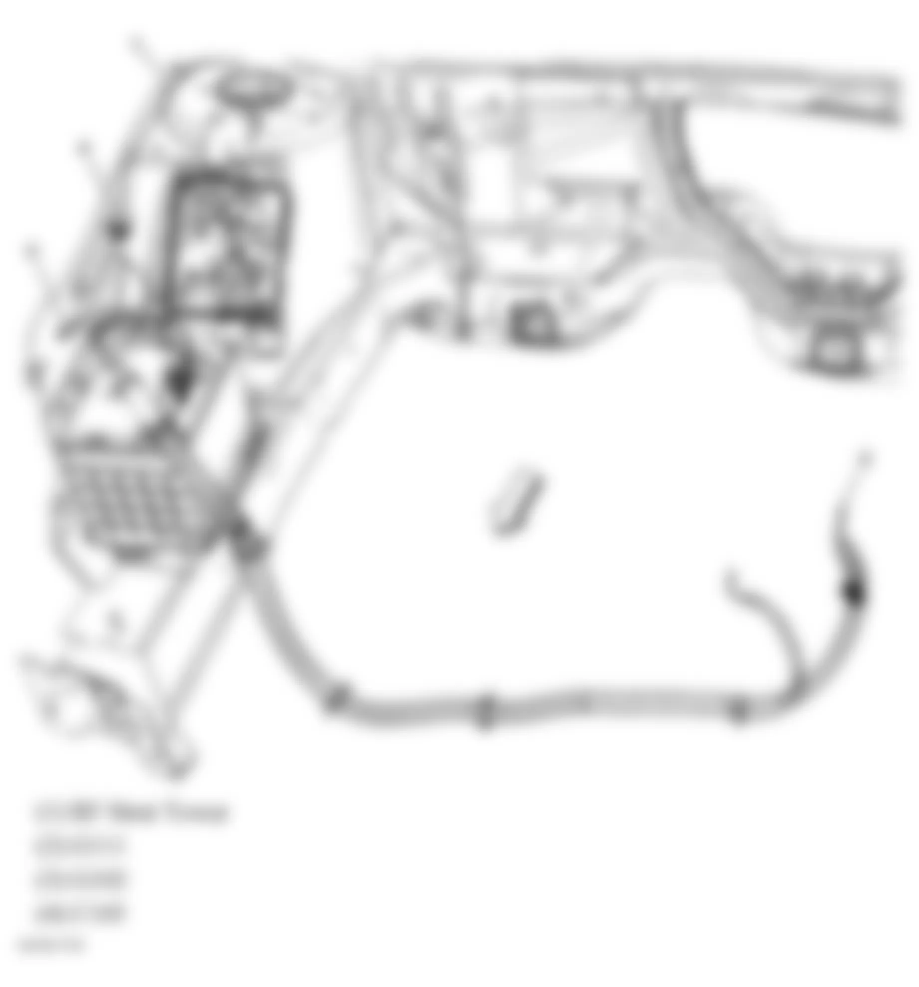
Fig. 8: Chevrolet Monte Carlo SS 2006 - Component Locations - Left Side Of Rear Compartment
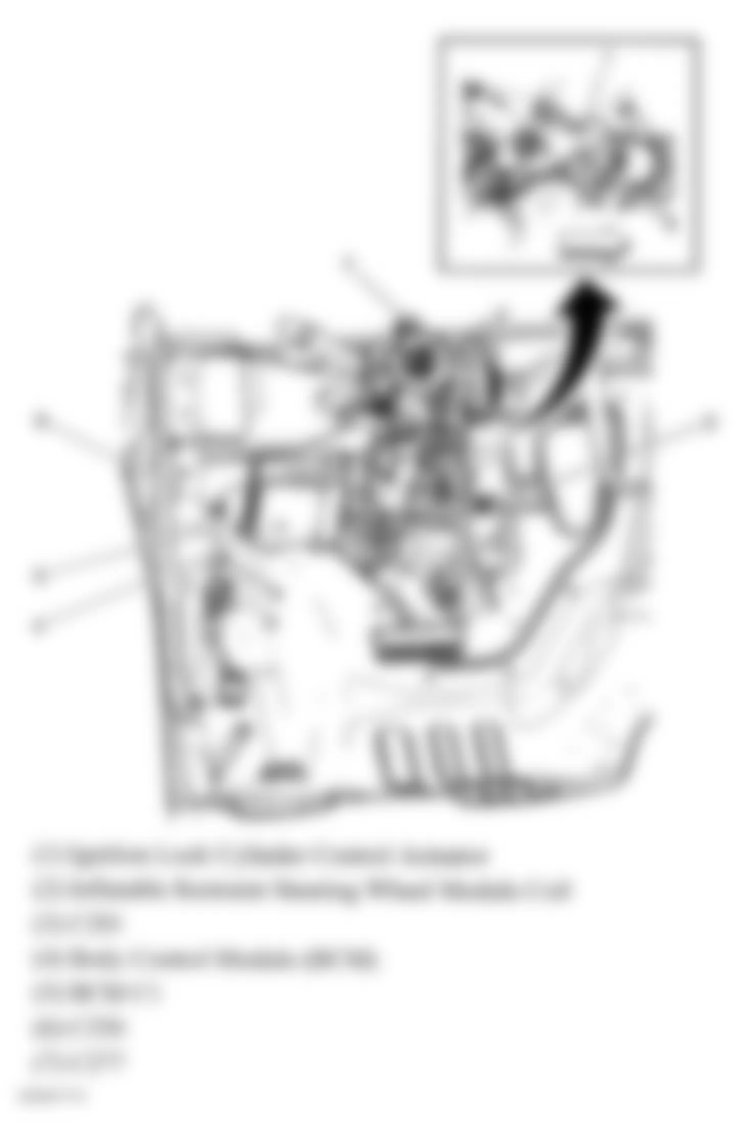
Fig. 9: Chevrolet Monte Carlo SS 2006 - Component Locations - Steering Column Assembly
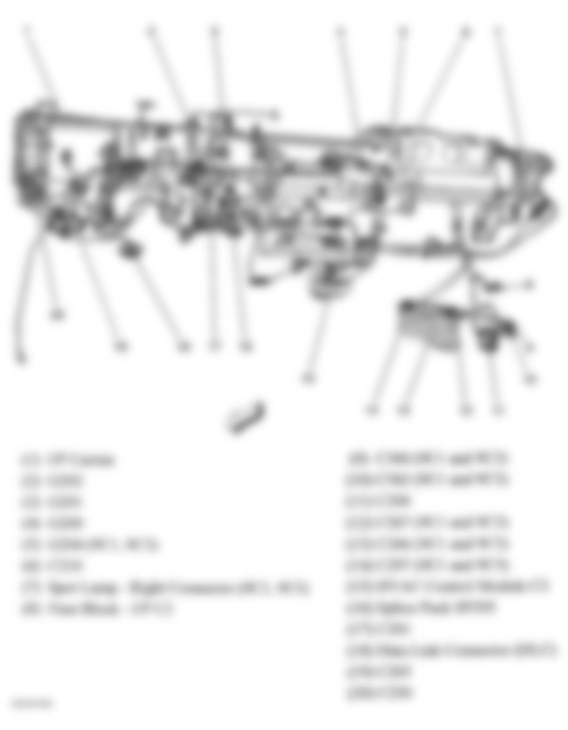
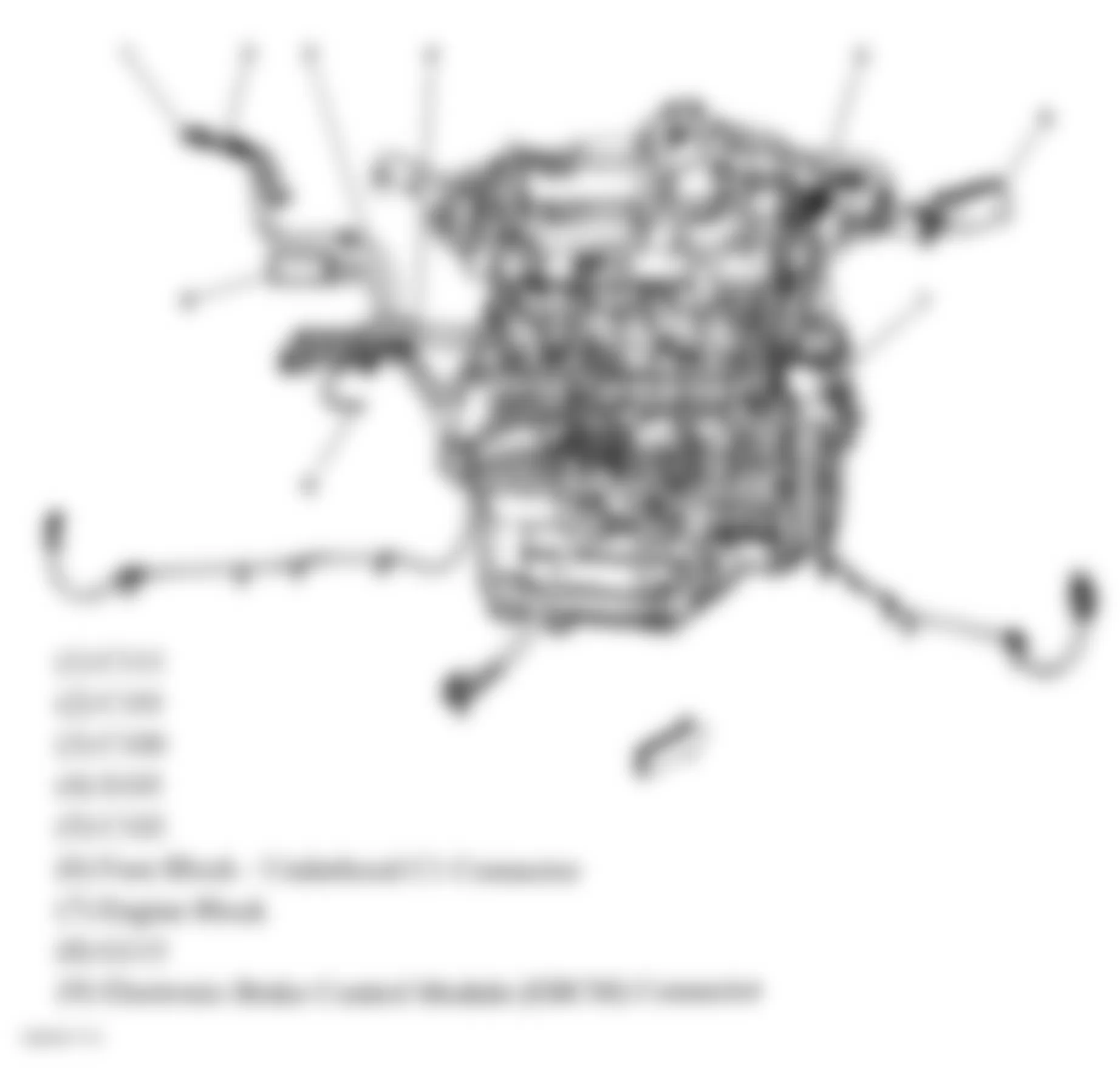
Fig. 10: Chevrolet Monte Carlo SS 2006 - Component Locations - Dash Harness
Fig. 11: Chevrolet Monte Carlo SS 2006 - Component Locations - Lower Left Side Of Dash
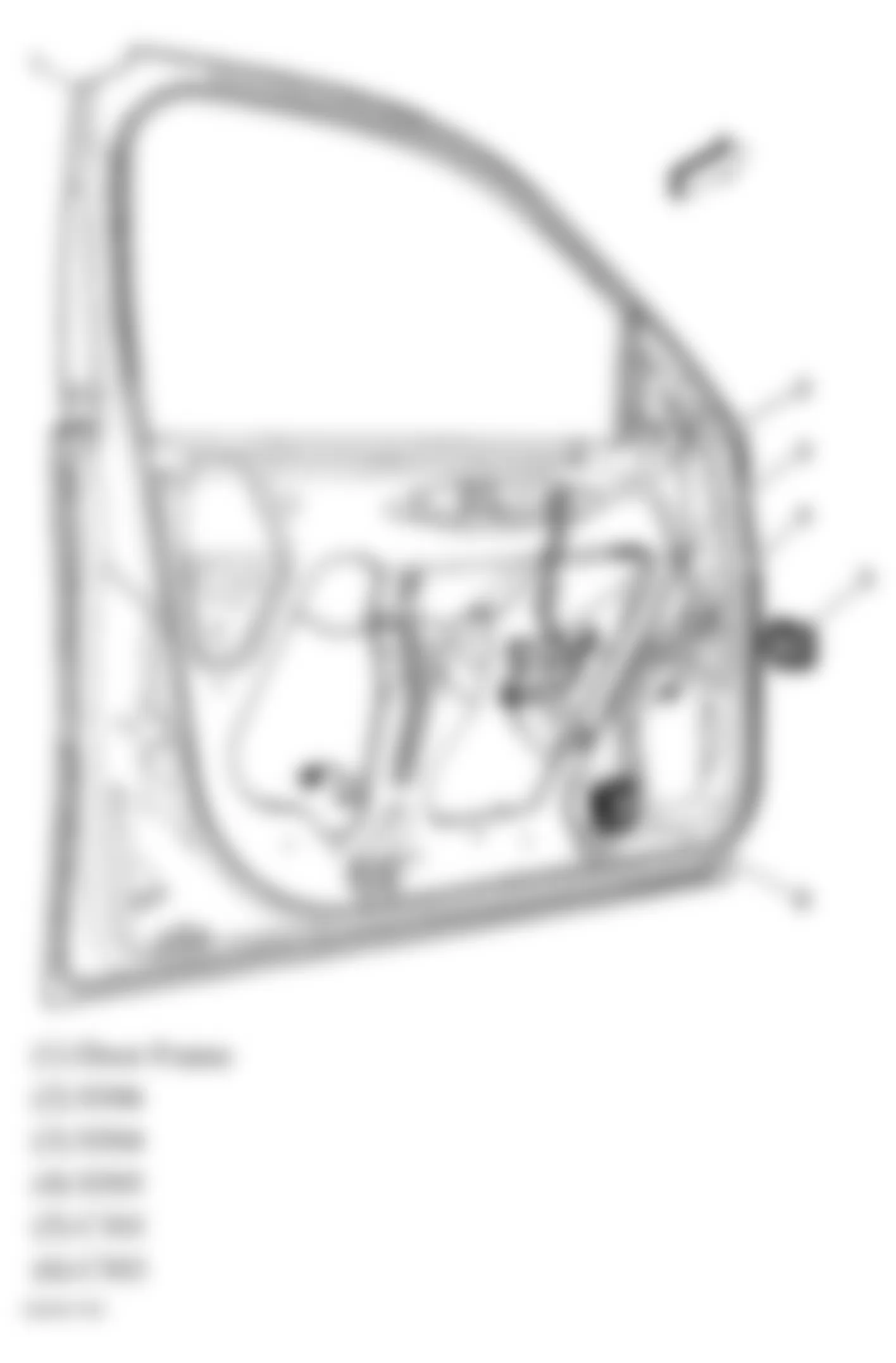
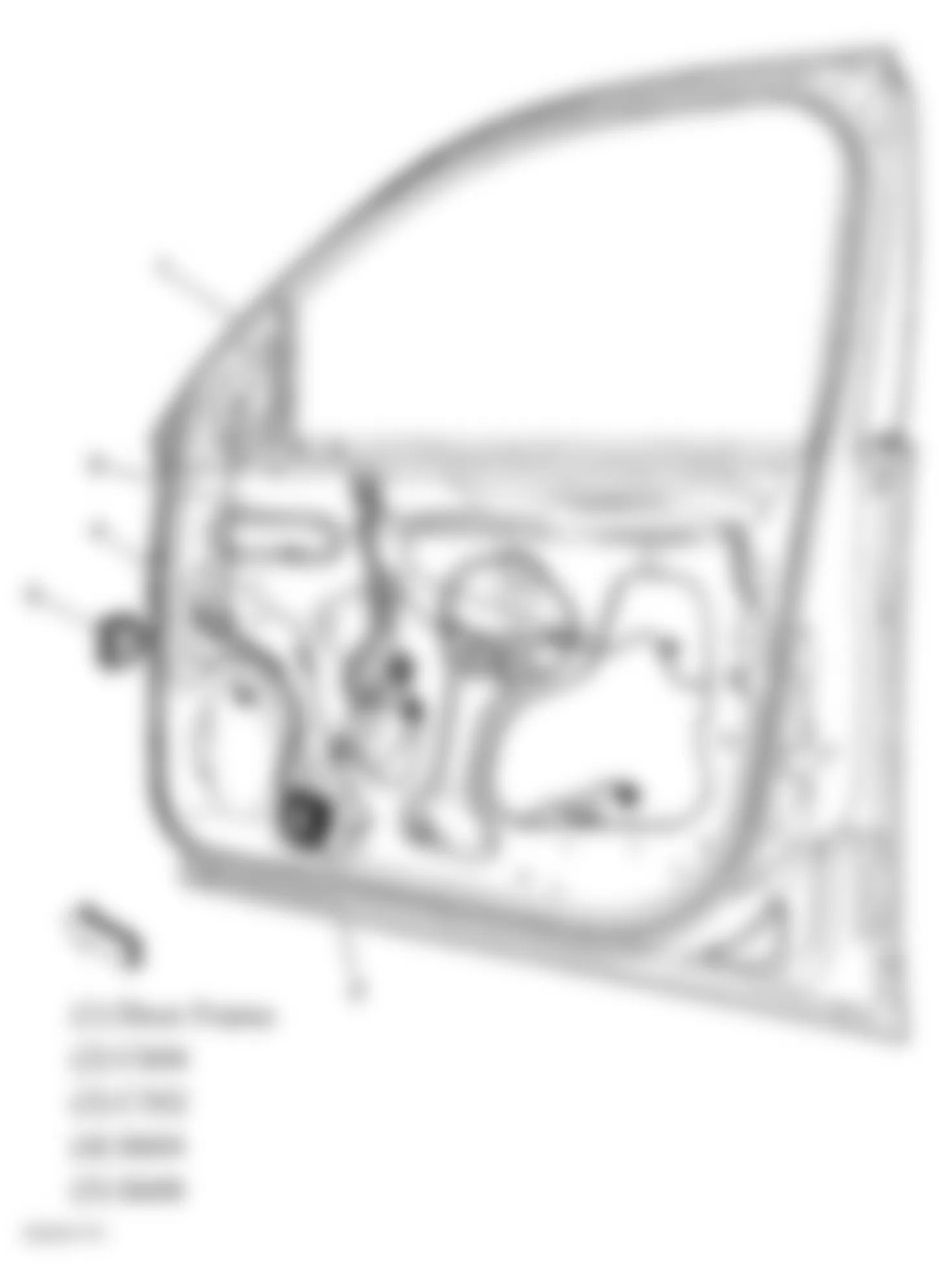
Fig. 12: Chevrolet Monte Carlo SS 2006 - Component Locations - Driver Door (Sedan)
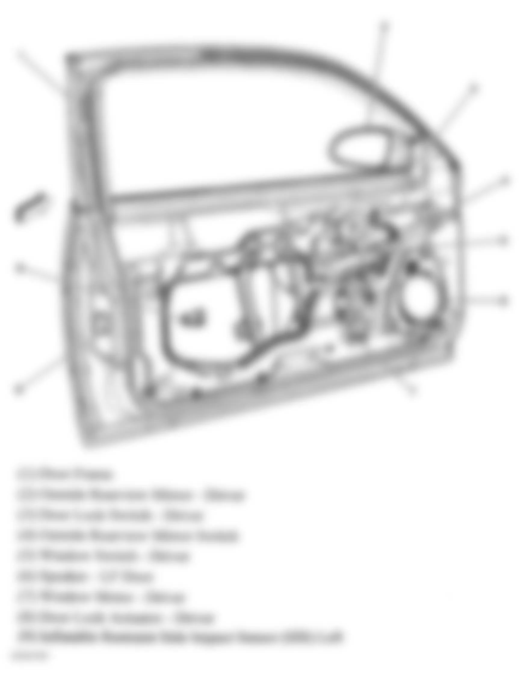
Fig. 13: Chevrolet Monte Carlo SS 2006 - Component Locations - Left Front Door (Coupe)
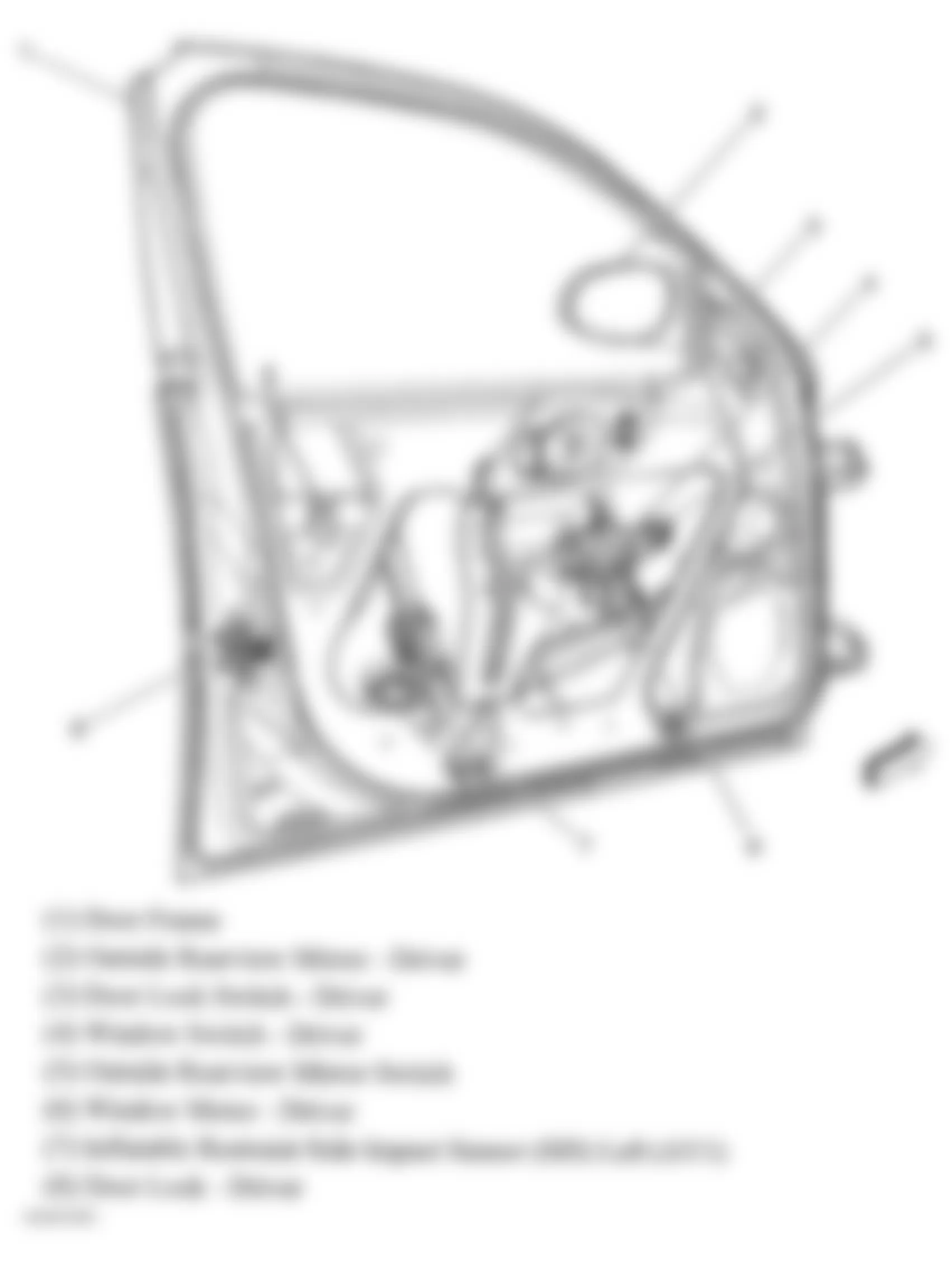
Fig. 14: Chevrolet Monte Carlo SS 2006 - Component Locations - Front Passenger Door (Sedan)
Fig. 15: Chevrolet Monte Carlo SS 2006 - Component Locations - Right Front Door Components (Coupe)
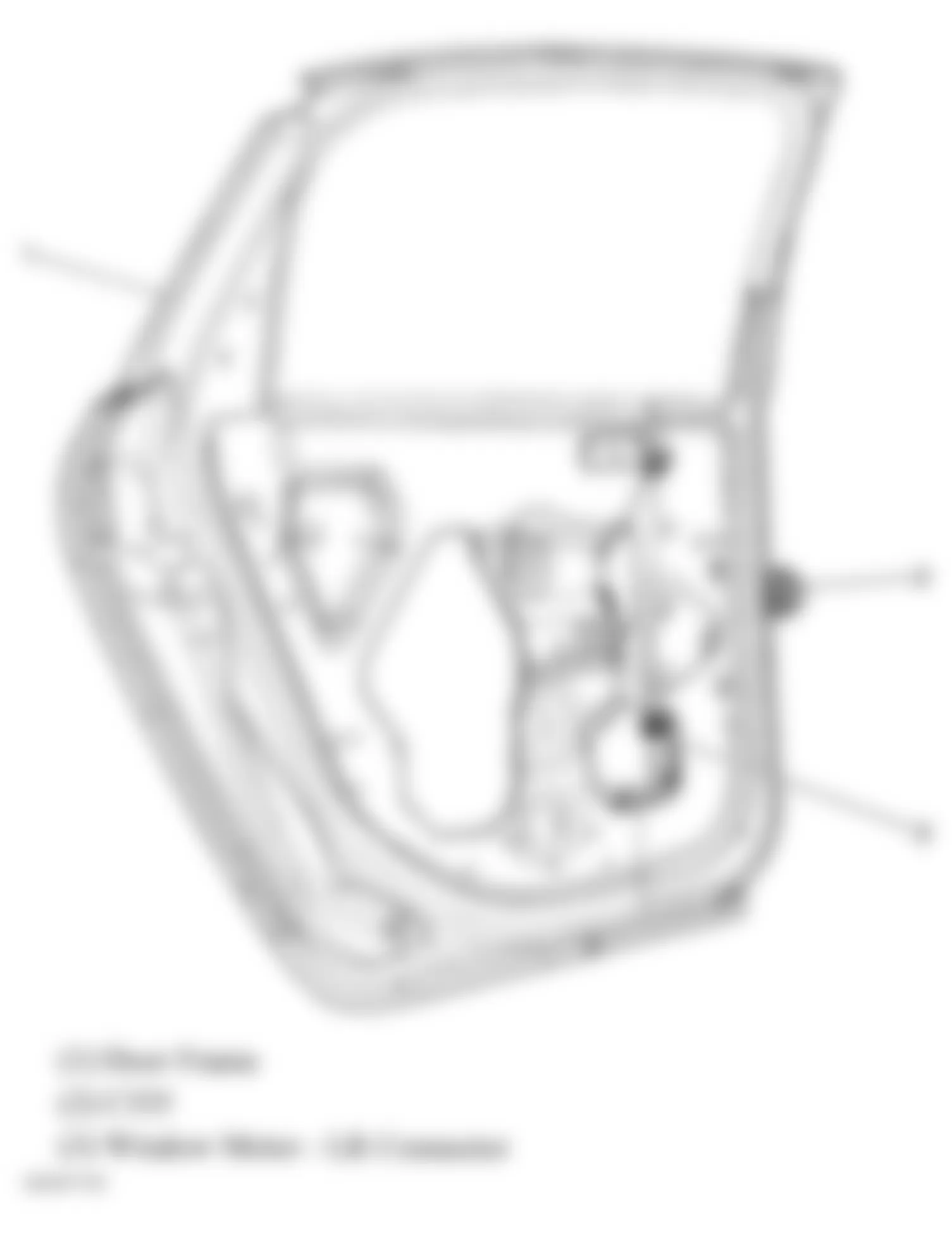
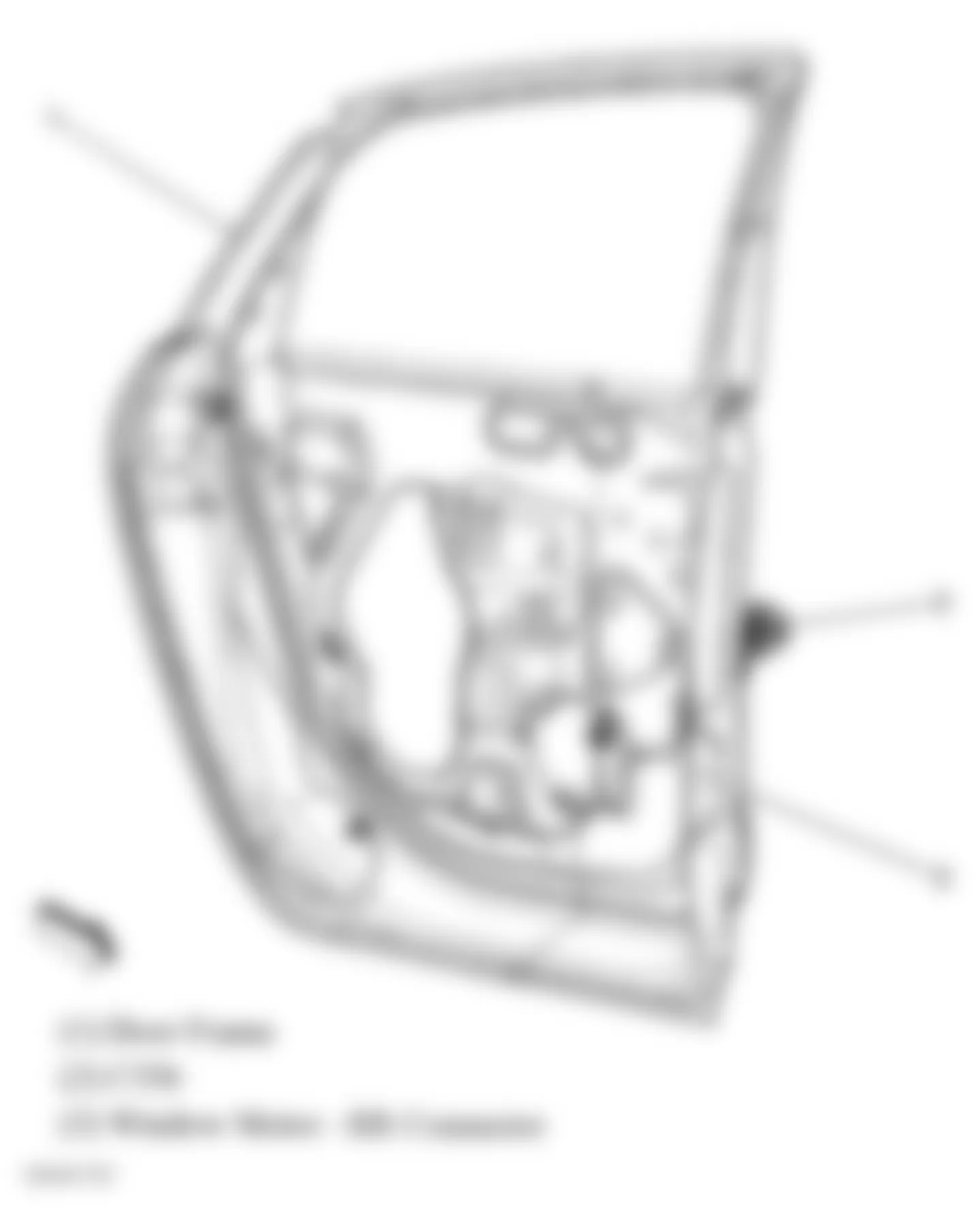
Fig. 16: Chevrolet Monte Carlo SS 2006 - Component Locations - Left Rear Door (Sedan)
Fig. 17: Chevrolet Monte Carlo SS 2006 - Component Locations - Right Rear Door (Sedan)
Fig. 18: Chevrolet Monte Carlo SS 2006 - Component Locations - Top Of Engine (3.5L & 3.9L)
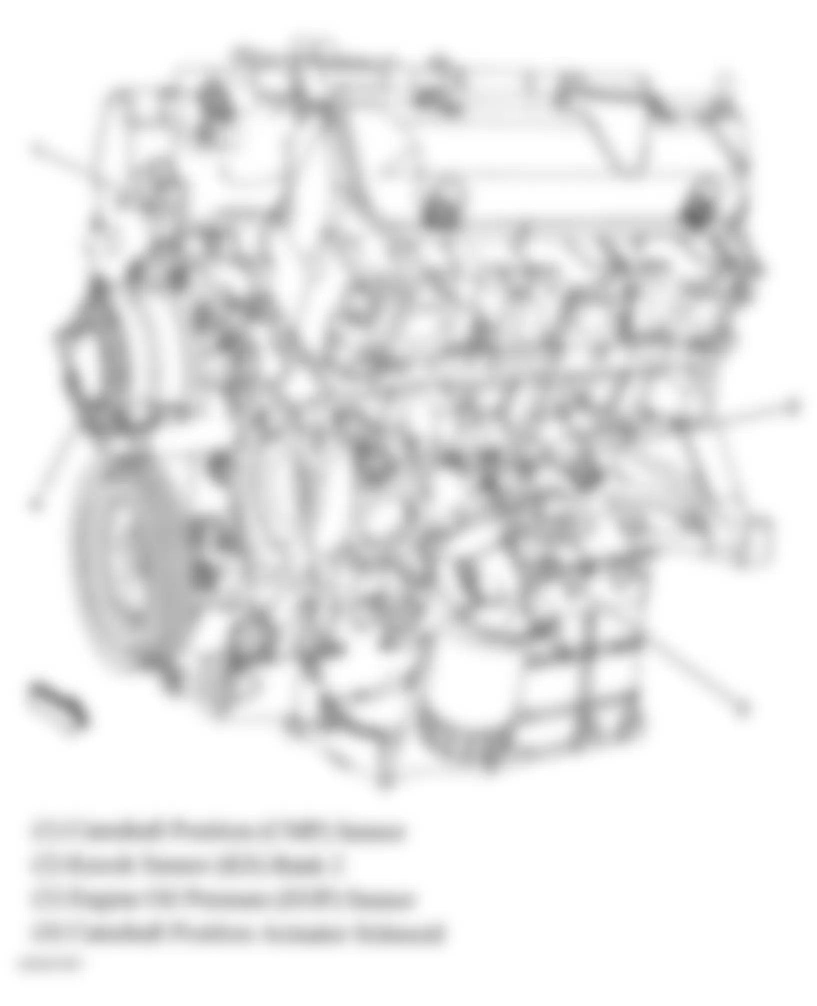
Fig. 19: Chevrolet Monte Carlo SS 2006 - Component Locations - Front Of Engine (3.5L & 3.9L)
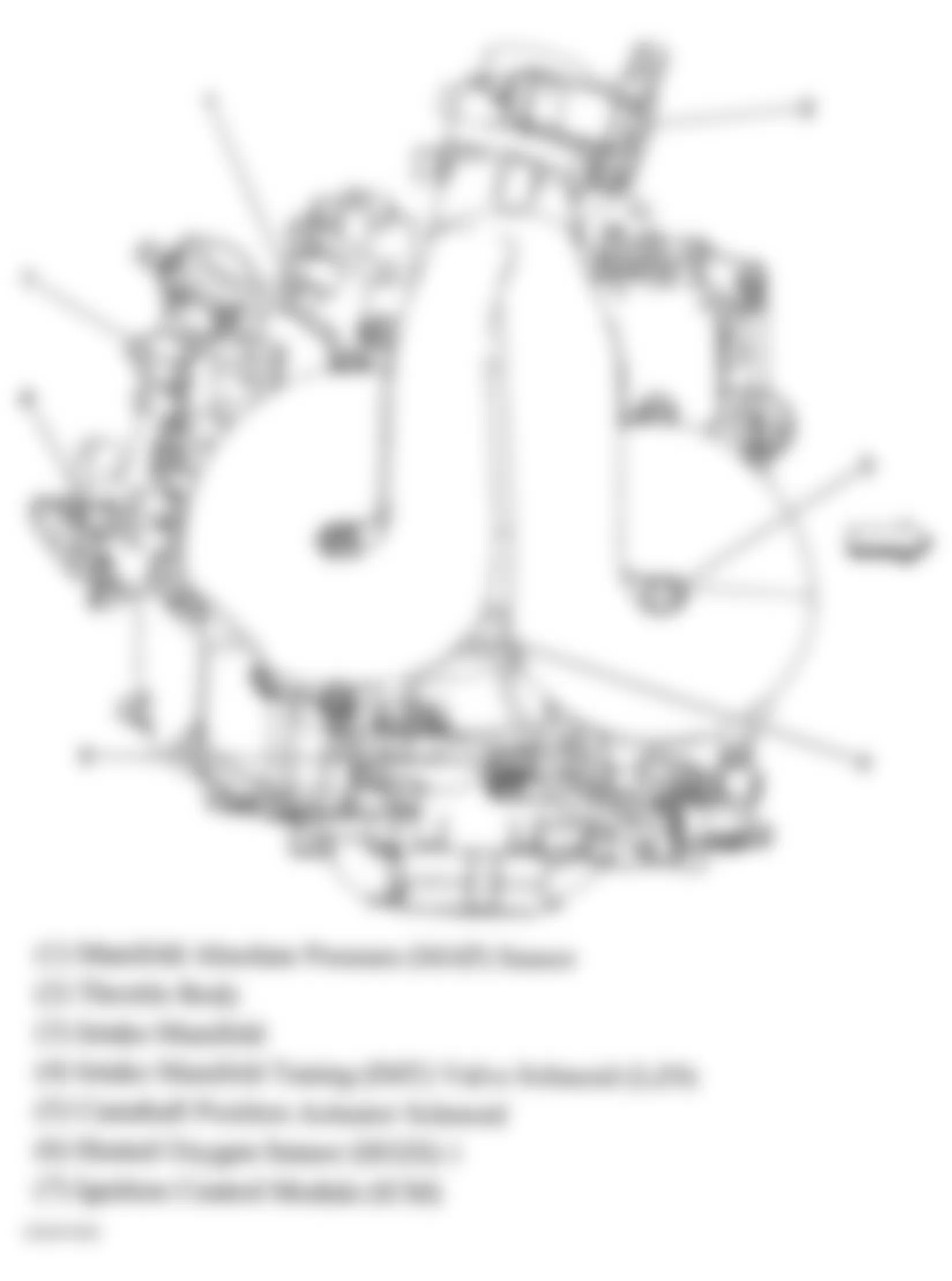
Fig. 20: Chevrolet Monte Carlo SS 2006 - Component Locations - Top Of Engine (3.5L & 3.9L)
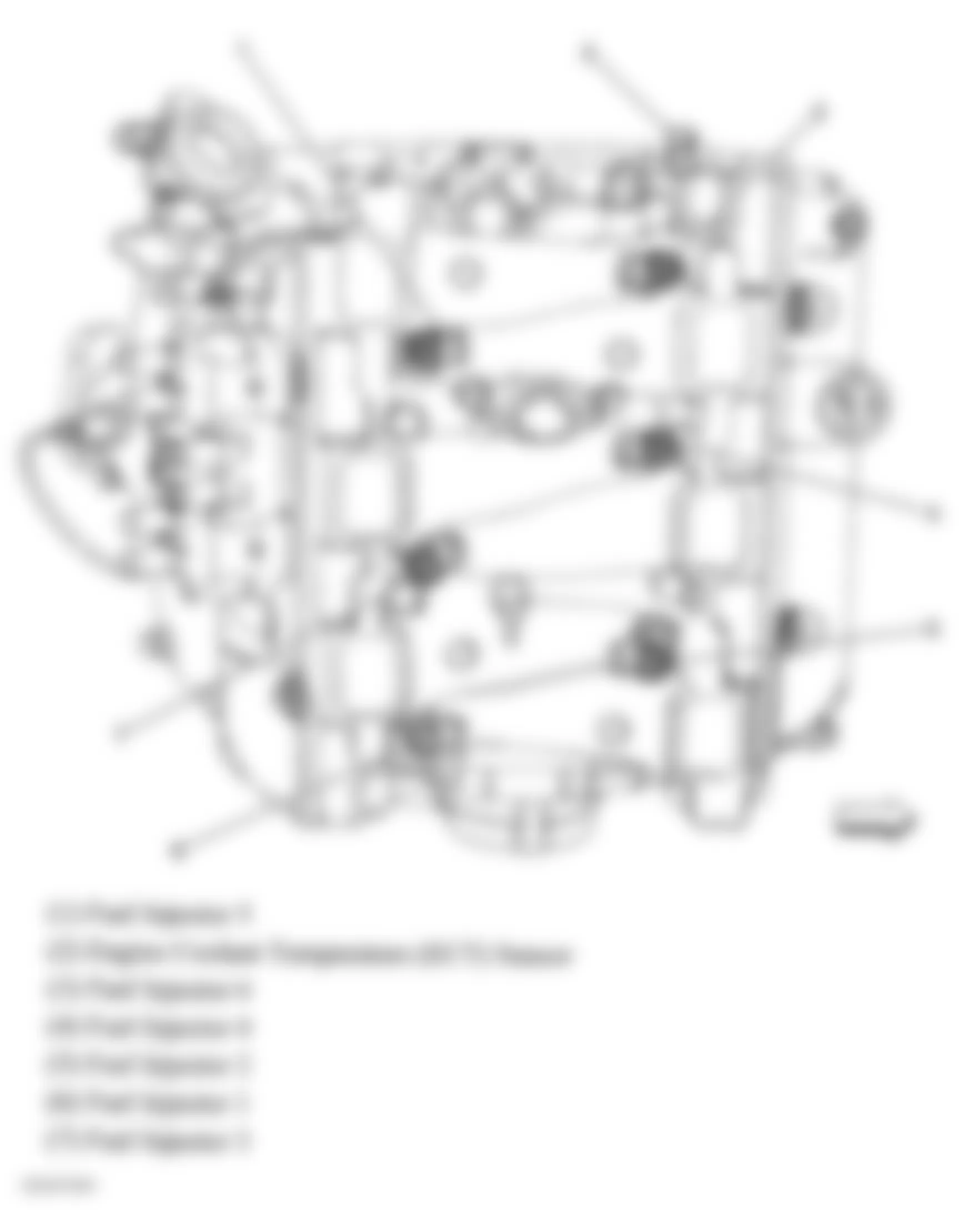
Fig. 21: Chevrolet Monte Carlo SS 2006 - Component Locations - Top Of Engine (3.5L & 3.9L)
Fig. 22: Chevrolet Monte Carlo SS 2006 - Component Locations - Right Side Of Engine (3.5L & 3.9L)
Fig. 23: Chevrolet Monte Carlo SS 2006 - Component Locations - Exhaust
Fig. 24: Chevrolet Monte Carlo SS 2006 - Component Locations - Pedal Assembly
Fig. 25: Chevrolet Monte Carlo SS 2006 - Component Locations - Fuel Tank Assembly
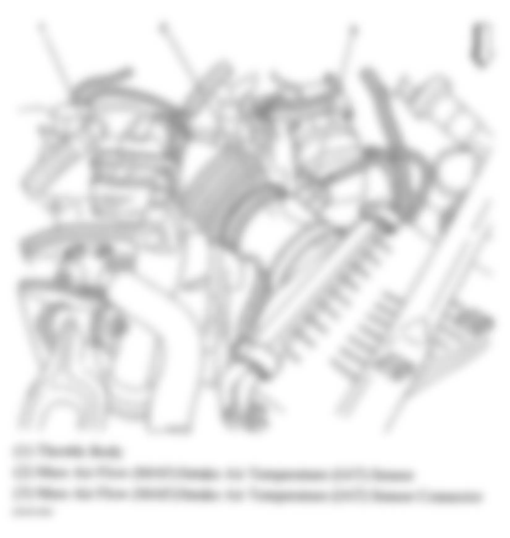
Fig. 26: Chevrolet Monte Carlo SS 2006 - Component Locations - Top Of Engine
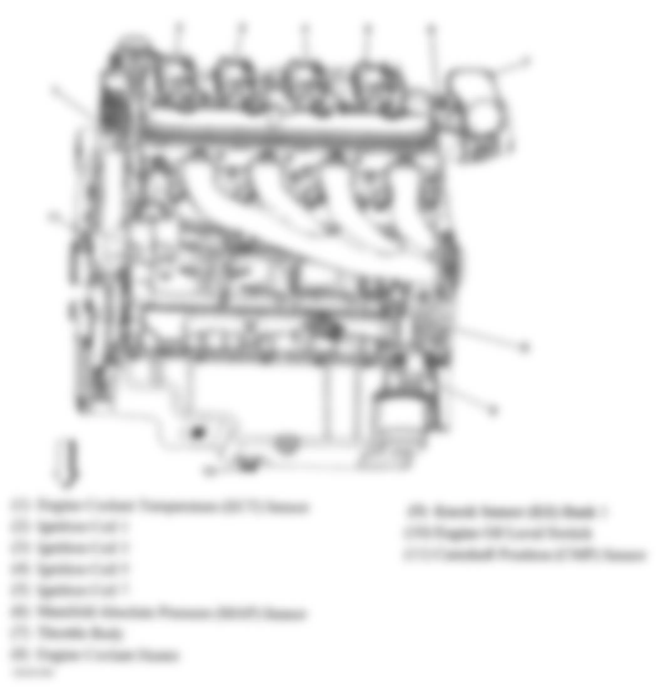
Fig. 27: Chevrolet Monte Carlo SS 2006 - Component Locations - Left Side Of Engine (5.3L)
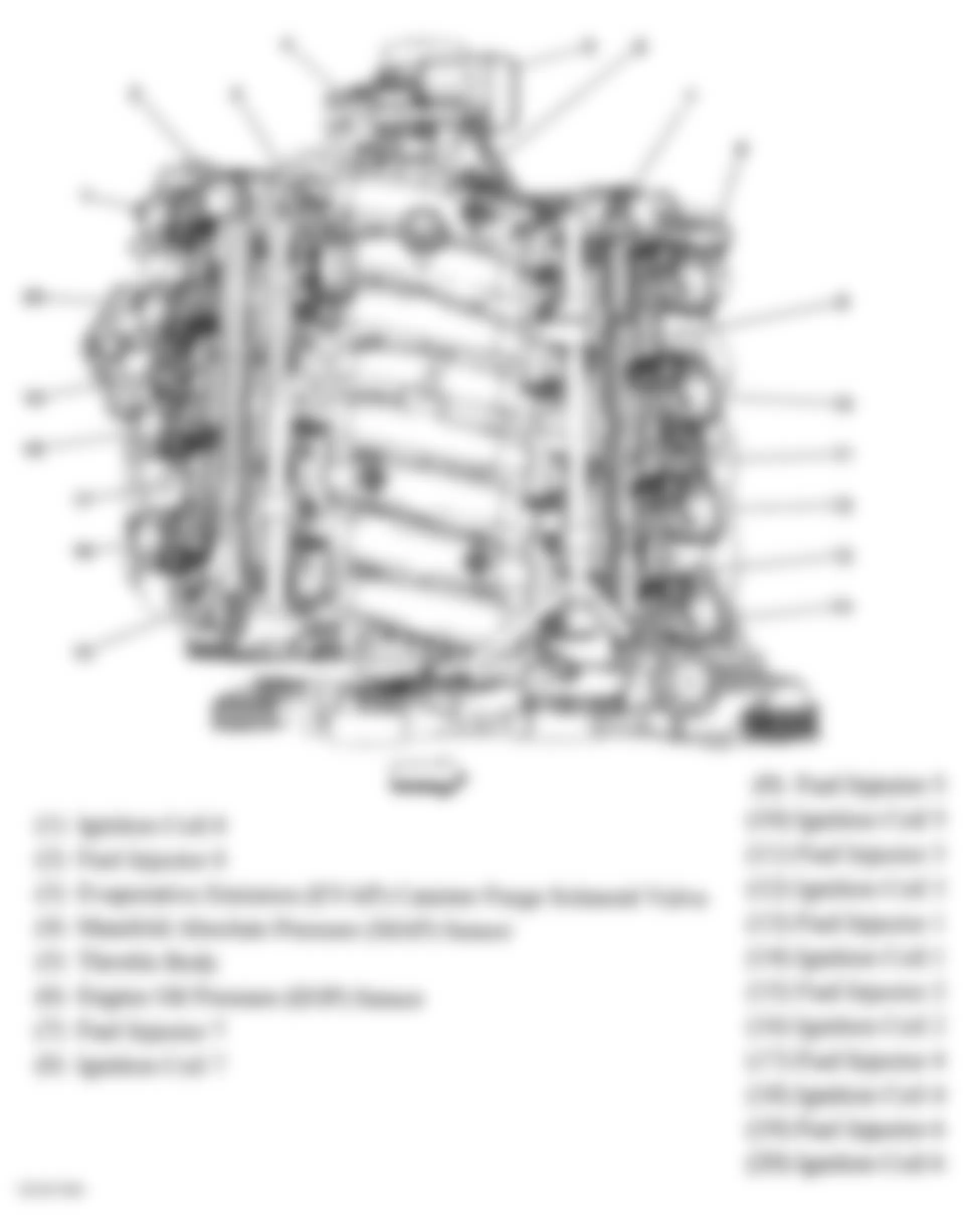
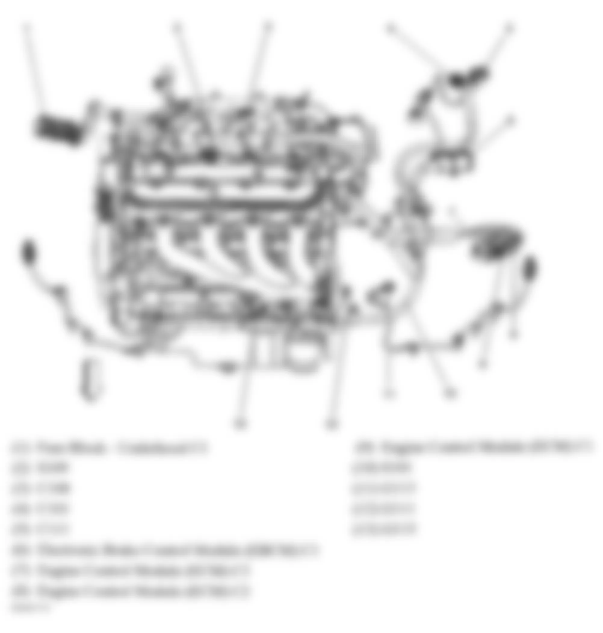
Fig. 28: Chevrolet Monte Carlo SS 2006 - Component Locations - Top Of Engine (5.3L)
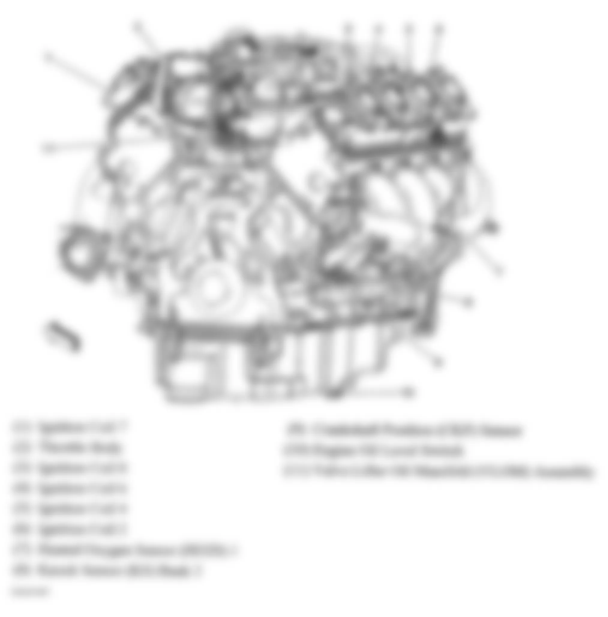
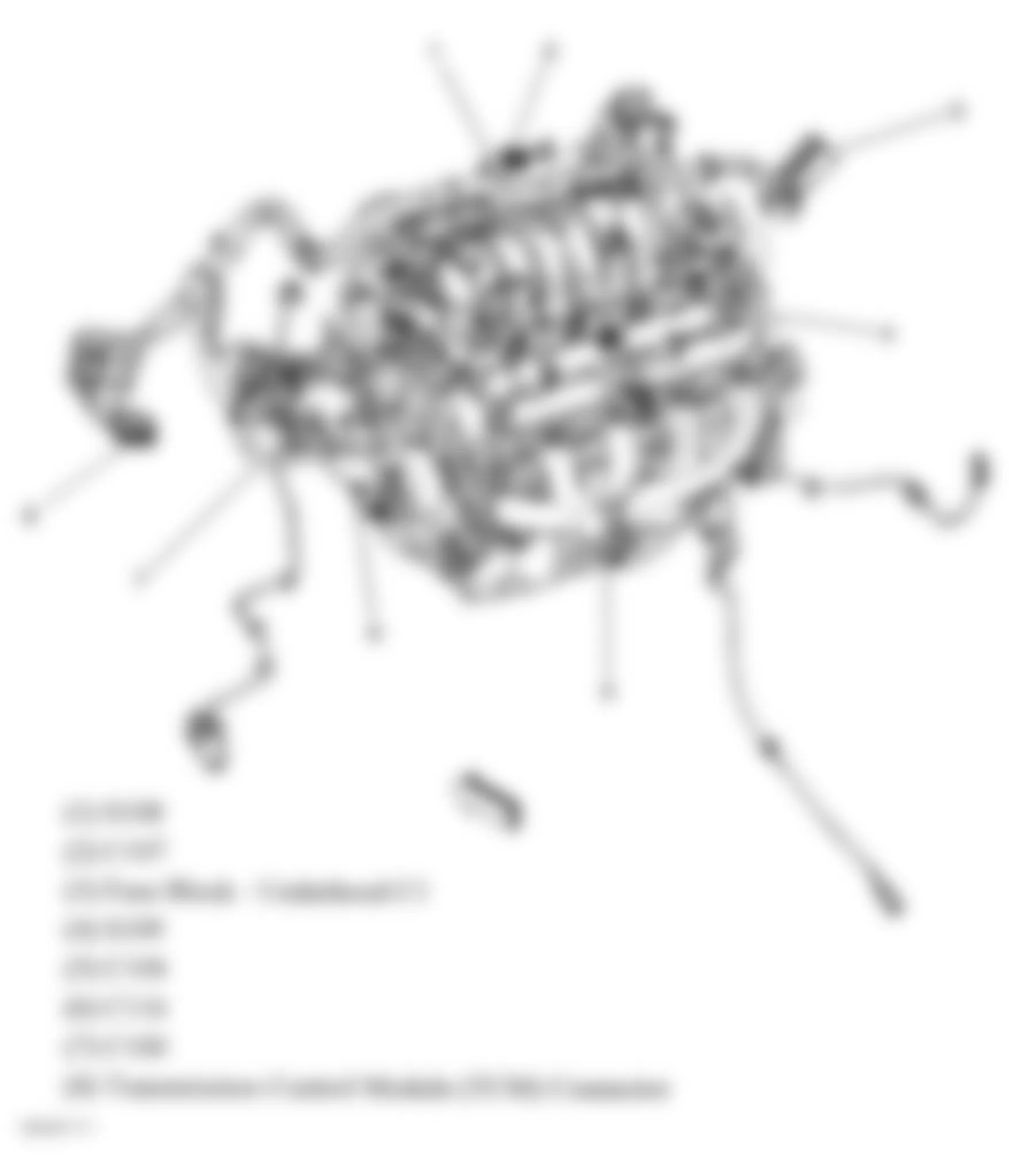
Fig. 29: Chevrolet Monte Carlo SS 2006 - Component Locations - Rear Of Engine (5.3L)
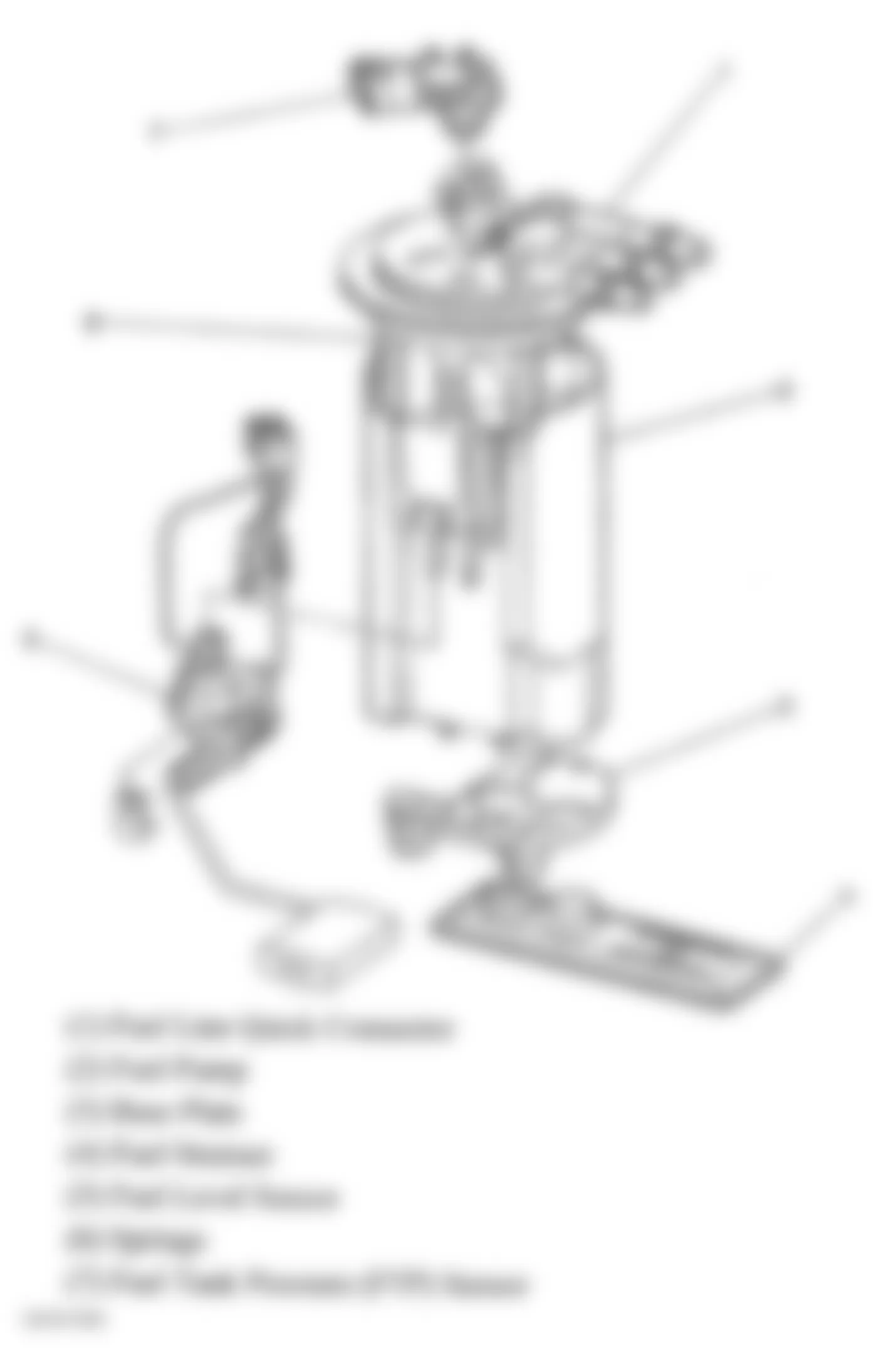
Fig. 30: Chevrolet Monte Carlo SS 2006 - Component Locations - Fuel Pump & Sender Assembly
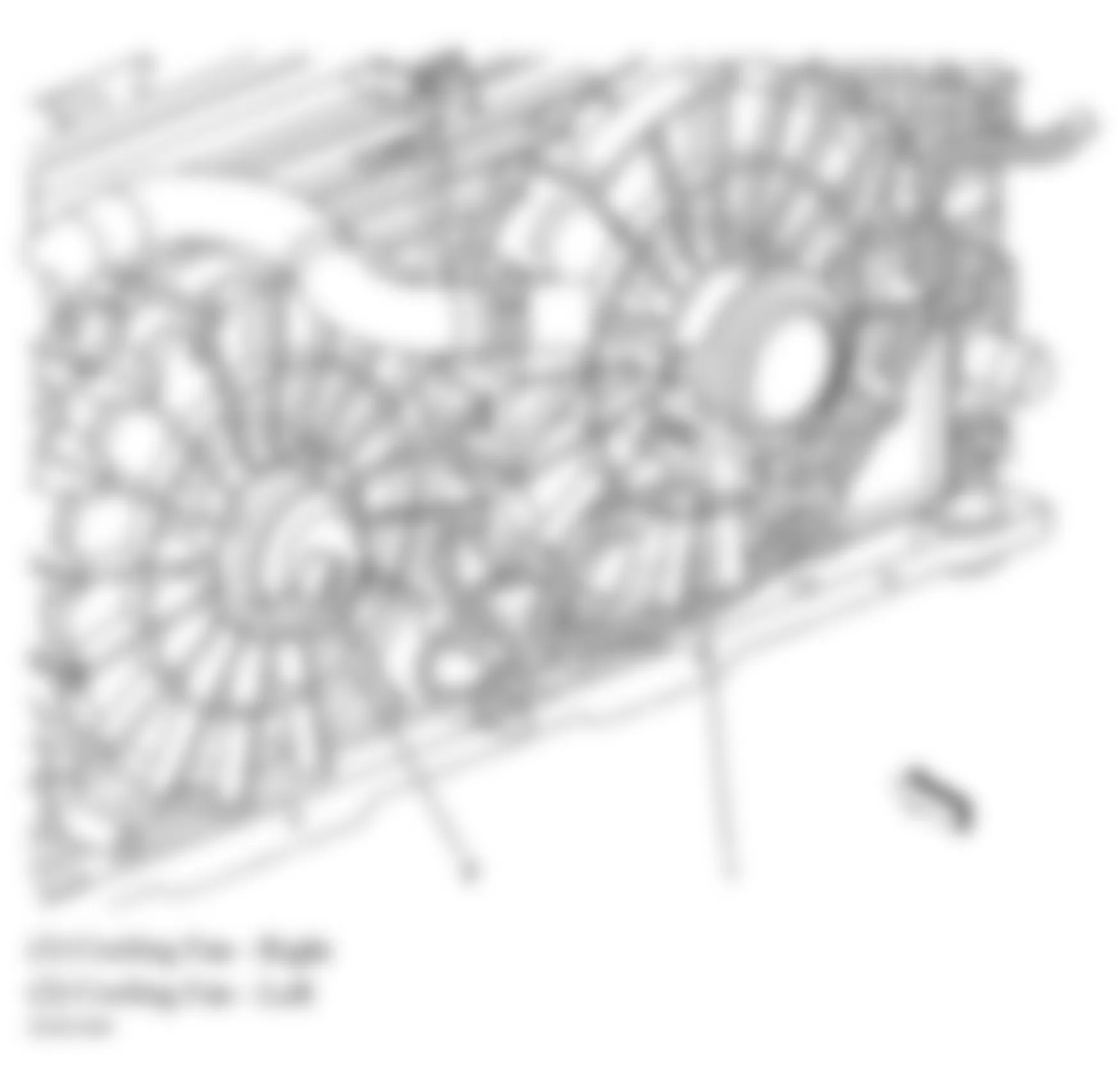
Fig. 31: Chevrolet Monte Carlo SS 2006 - Component Locations - Cooling System Component Views
Fig. 32: Chevrolet Monte Carlo SS 2006 - Component Locations - Lower Front Of Engine (3.5L & 3.9L)
Fig. 33: Chevrolet Monte Carlo SS 2006 - Component Locations - Rear Of Engine Assembly (5.3L)
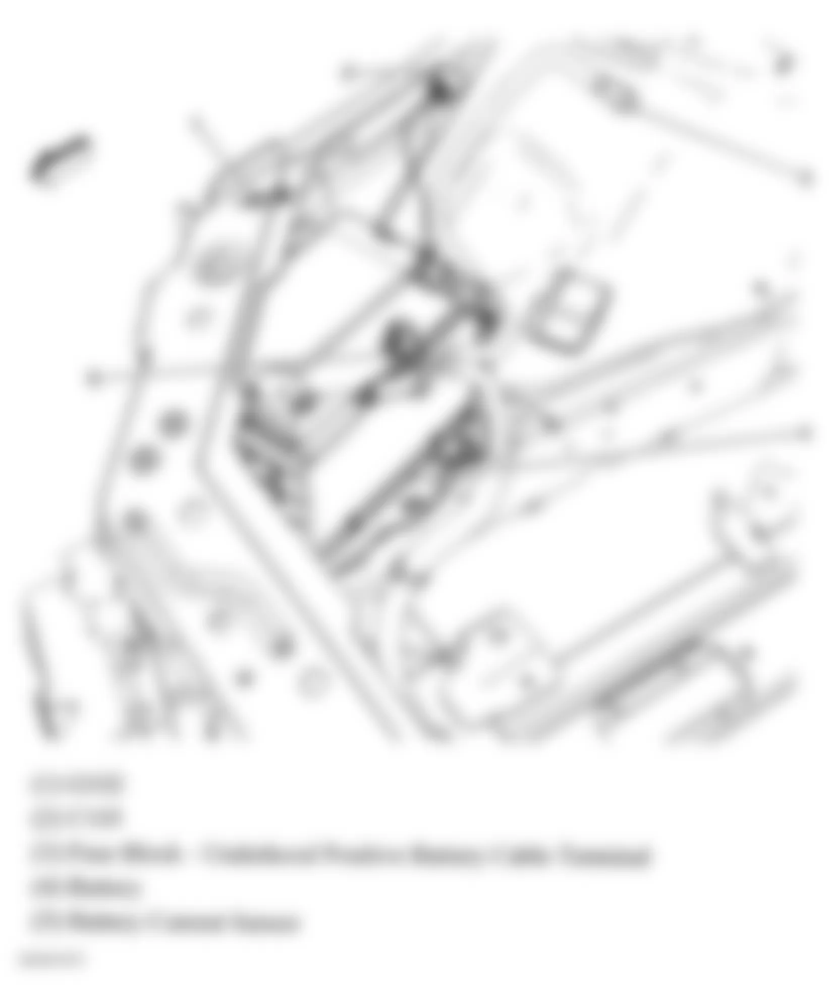
Fig. 34: Chevrolet Monte Carlo SS 2006 - Component Locations - Right Front Of Engine Compartment
Fig. 35: Chevrolet Monte Carlo SS 2006 - Component Locations - Right Front Of Vehicle (3.5L & 3.9L)
Fig. 36: Chevrolet Monte Carlo SS 2006 - Component Locations - Interior Overview
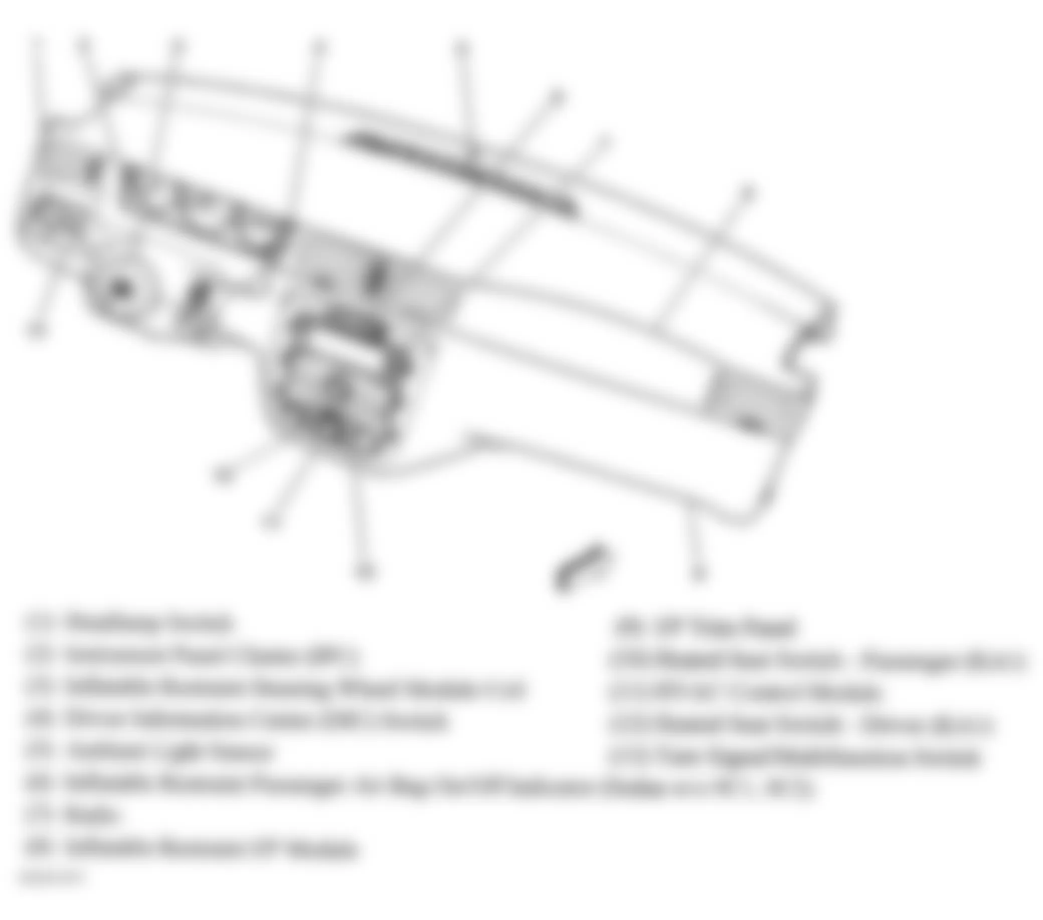
Fig. 37: Chevrolet Monte Carlo SS 2006 - Component Locations - Dash Components
Fig. 38: Chevrolet Monte Carlo SS 2006 - Component Locations - Rear Seat
Fig. 39: Chevrolet Monte Carlo SS 2006 - Component Locations - Right Side Of Luggage Compartment
Fig. 40: Chevrolet Monte Carlo SS 2006 - Component Locations - Lower Left Front Of Engine
Fig. 41: Chevrolet Monte Carlo SS 2006 - Component Locations - HVAC Components
Fig. 42: Chevrolet Monte Carlo SS 2006 - Component Locations - Left Rear Of Engine Compartment
Fig. 43: Chevrolet Monte Carlo SS 2006 - Component Locations - Front Of Engine Compartment
Fig. 44: Chevrolet Monte Carlo SS 2006 - Component Locations - Left Side Of Windshield
Fig. 45: Chevrolet Monte Carlo SS 2006 - Component Locations - Upper Center Of Dash
Fig. 46: Chevrolet Monte Carlo SS 2006 - Component Locations - Right Front Of Engine Compartment
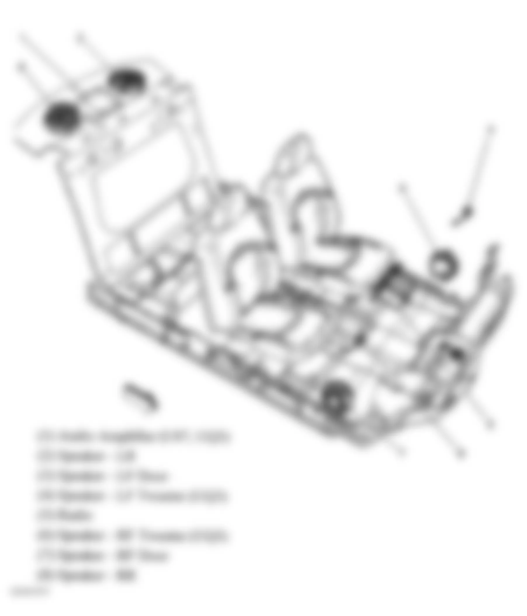
Fig. 47: Chevrolet Monte Carlo SS 2006 - Component Locations - Rear Package Shelf
Fig. 48: Chevrolet Monte Carlo SS 2006 - Component Locations - Right Front Of Rear Compartment
Fig. 49: Chevrolet Monte Carlo SS 2006 - Component Locations - Left "B" Pillar
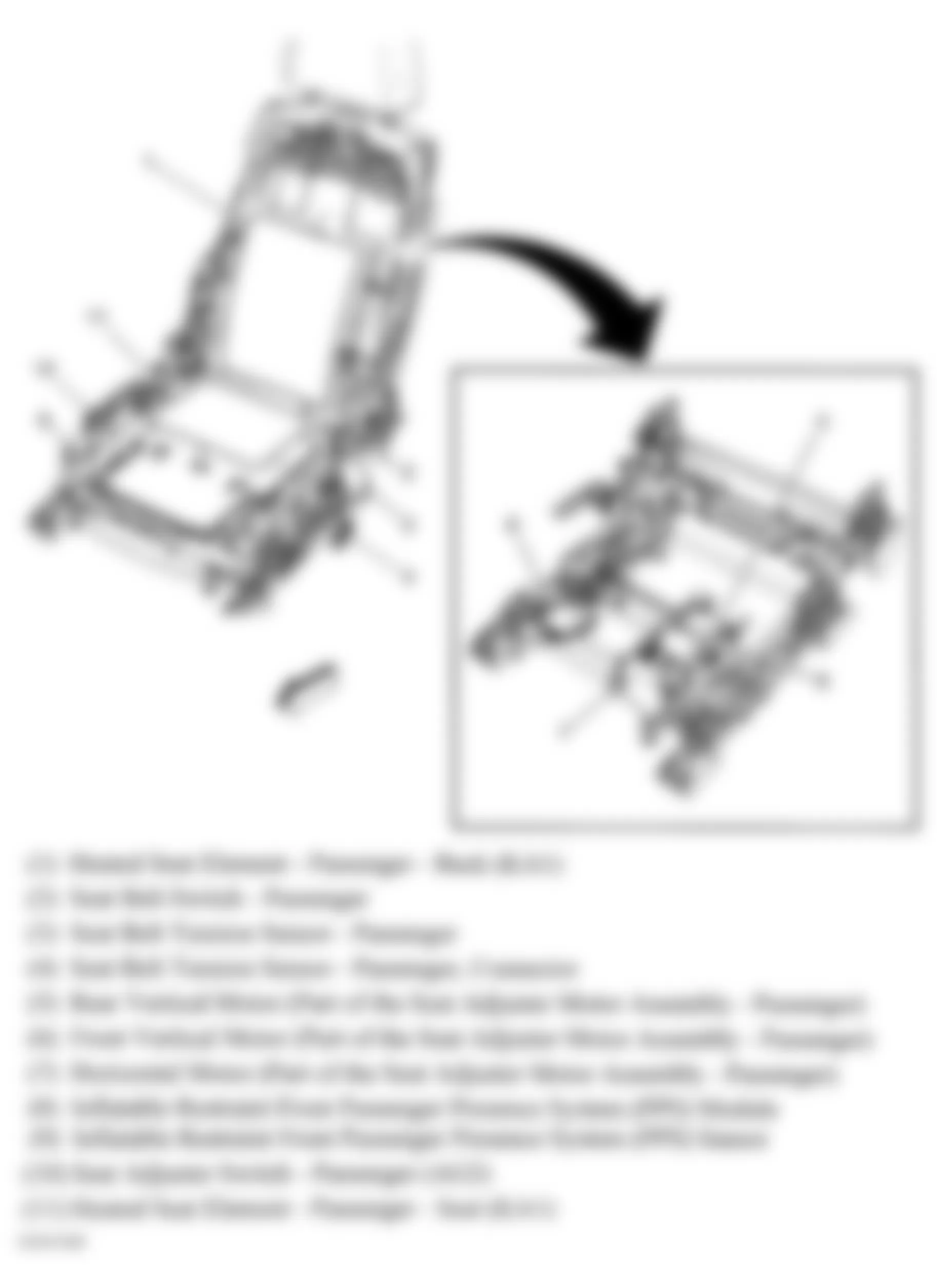
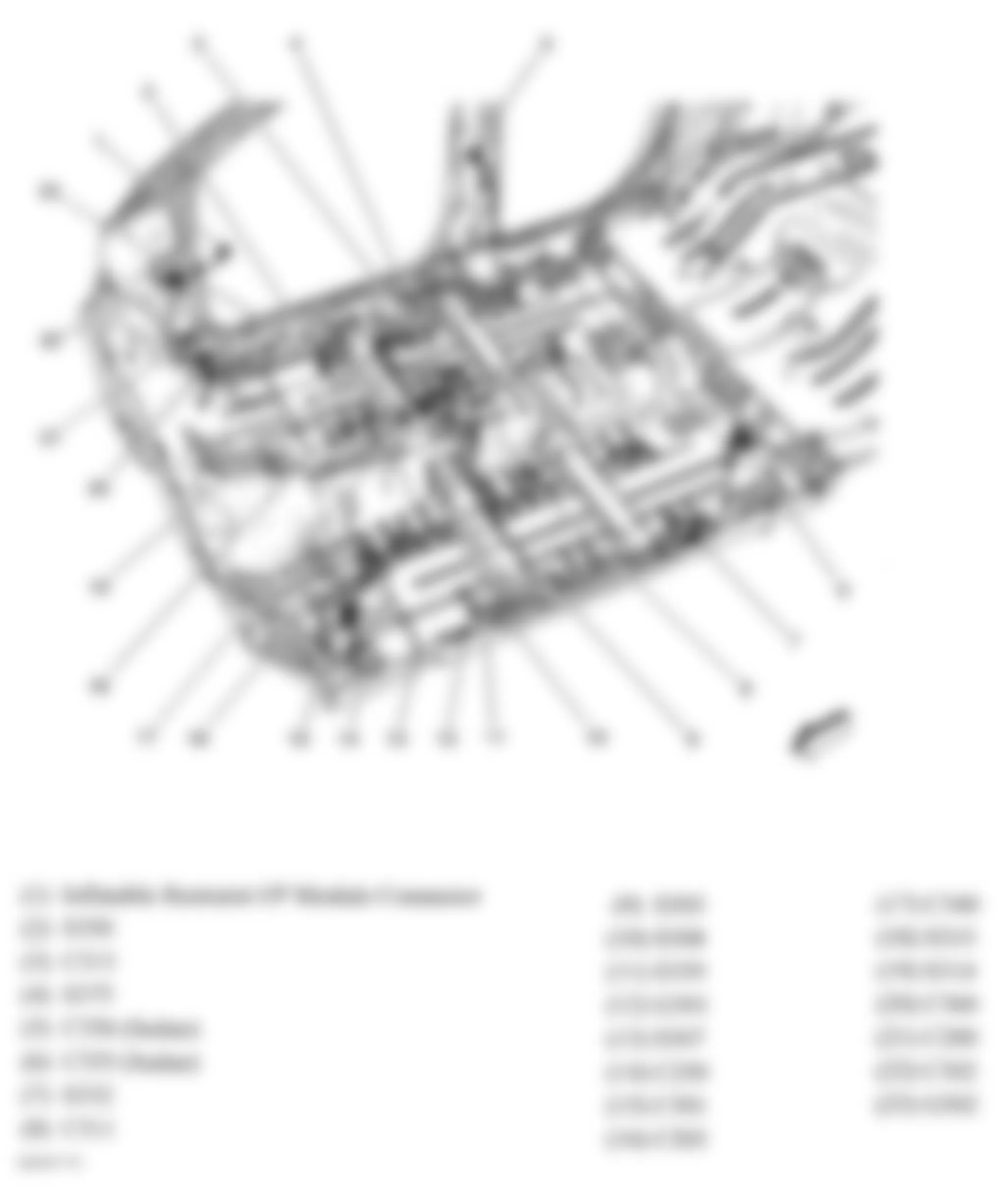
Fig. 50: Chevrolet Monte Carlo SS 2006 - Component Locations - Passenger's Seat
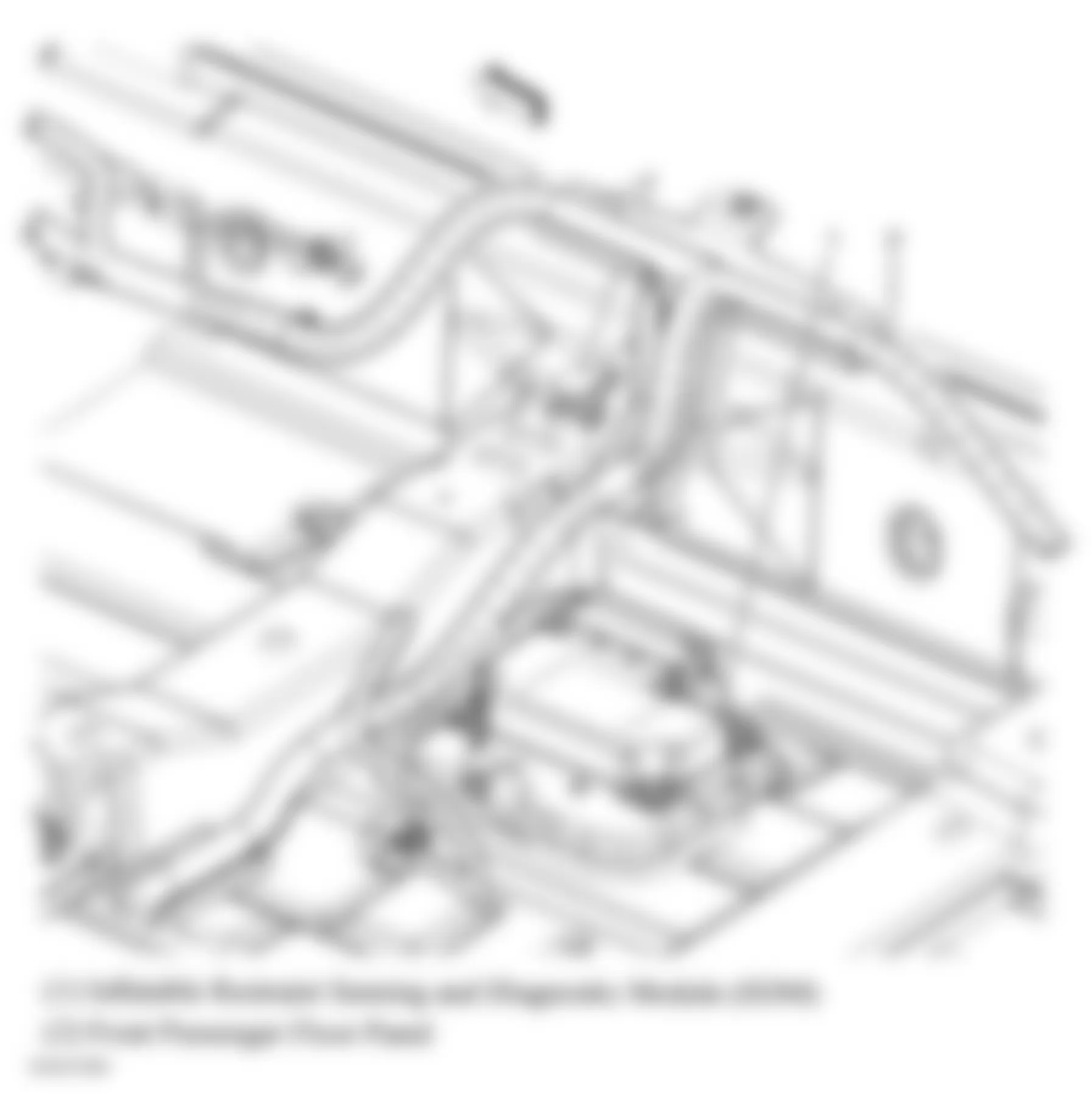
Fig. 51: Chevrolet Monte Carlo SS 2006 - Component Locations - Passenger's Floor Pan
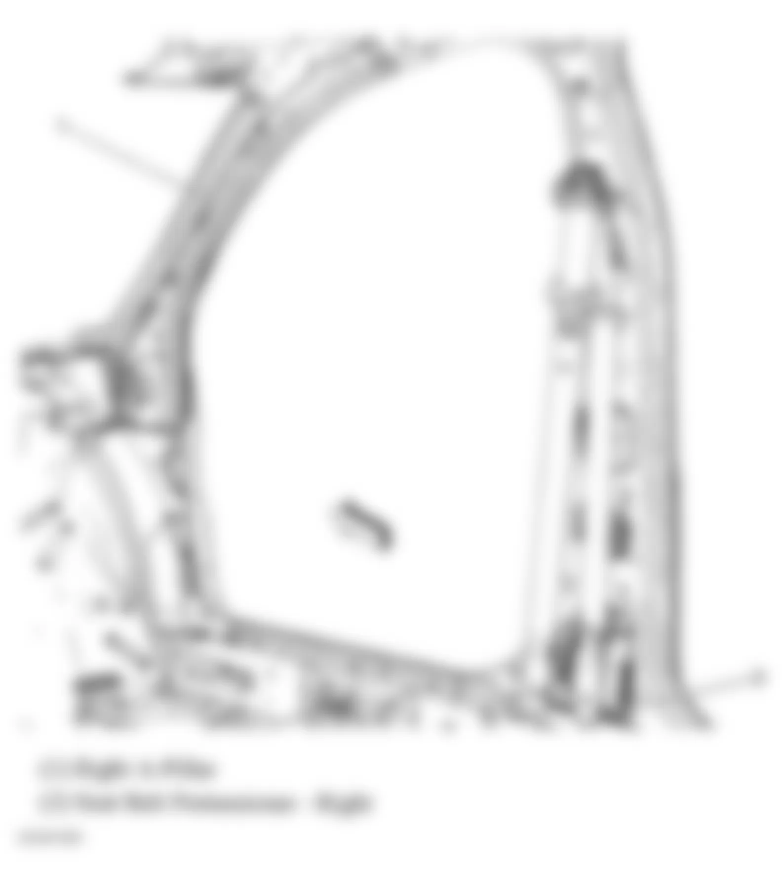
Fig. 52: Chevrolet Monte Carlo SS 2006 - Component Locations - Right "B" Pillar
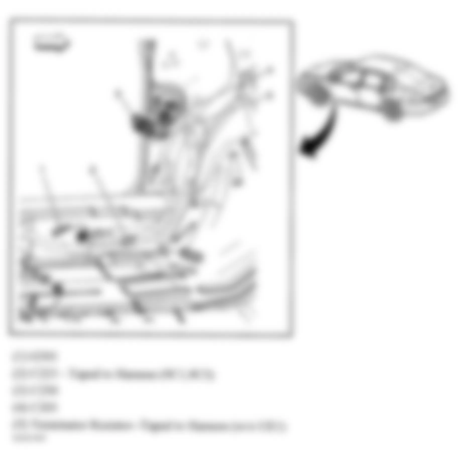
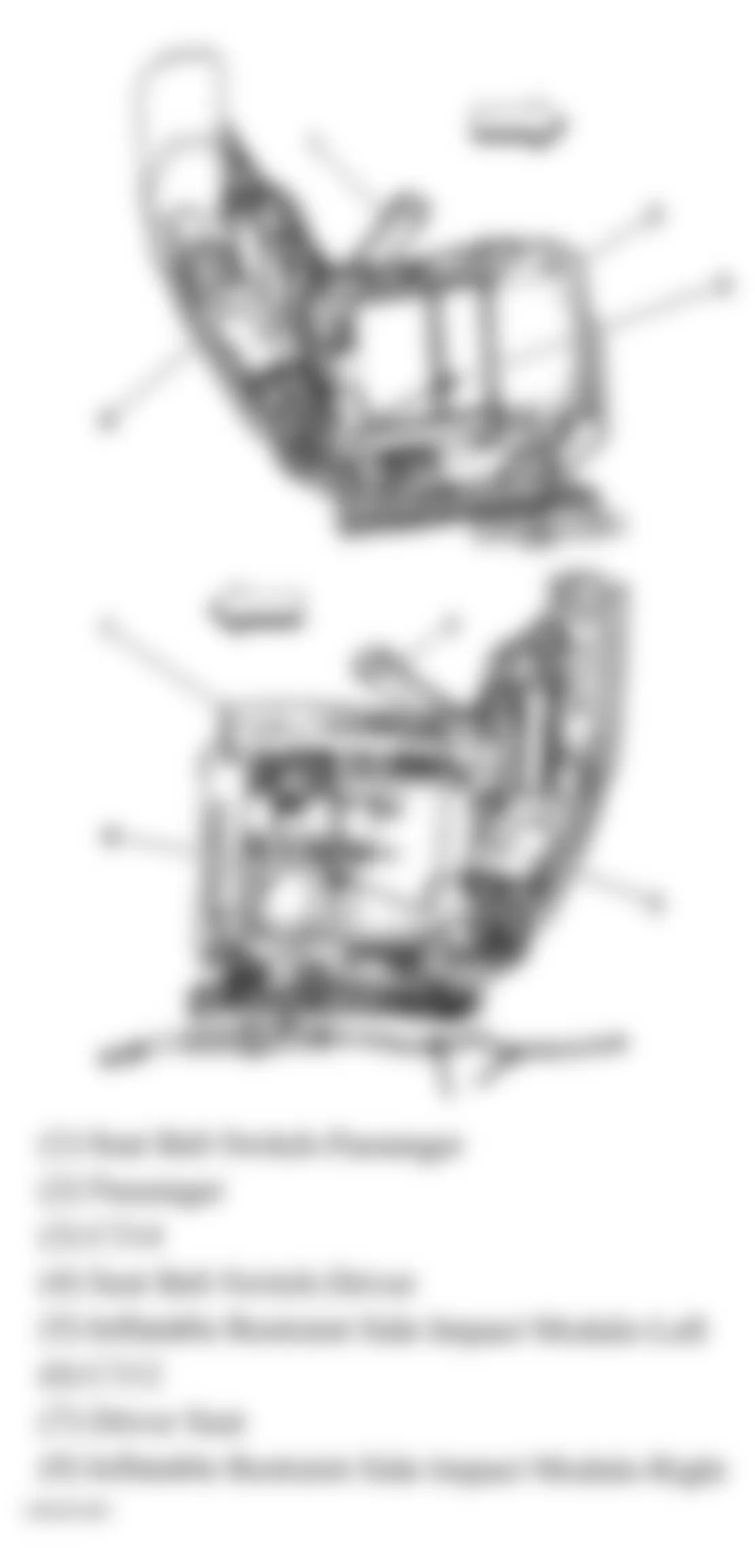
Fig. 53: Chevrolet Monte Carlo SS 2006 - Component Locations - Front Seats
Fig. 54: Chevrolet Monte Carlo SS 2006 - Component Locations - Vehicle Overview
Fig. 55: Chevrolet Monte Carlo SS 2006 - Component Locations - Left Front Seat
Fig. 56: Chevrolet Monte Carlo SS 2006 - Component Locations - Driver's Seat Components
Fig. 57: Chevrolet Monte Carlo SS 2006 - Component Locations - Steering Column Components
Fig. 58: Chevrolet Monte Carlo SS 2006 - Component Locations - Center Console
Fig. 59: Chevrolet Monte Carlo SS 2006 - Component Locations - Steering Column
Fig. 60: Chevrolet Monte Carlo SS 2006 - Component Locations - Wheel Assembly
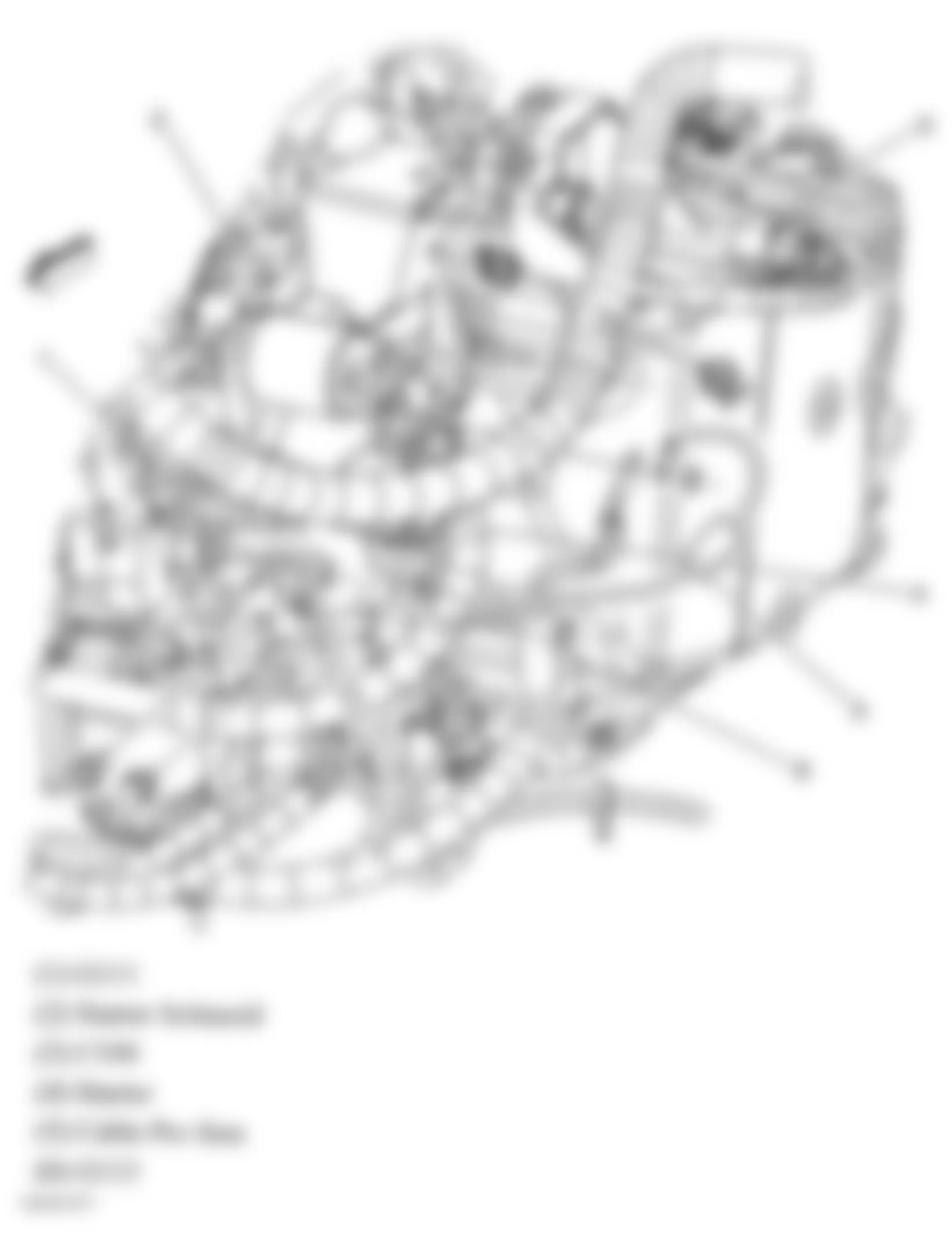
Fig. 62: Chevrolet Monte Carlo SS 2006 - Component Locations - Left Side Of Engine (5.3L)
Fig. 63: Chevrolet Monte Carlo SS 2006 - Component Locations - Engine Compartment
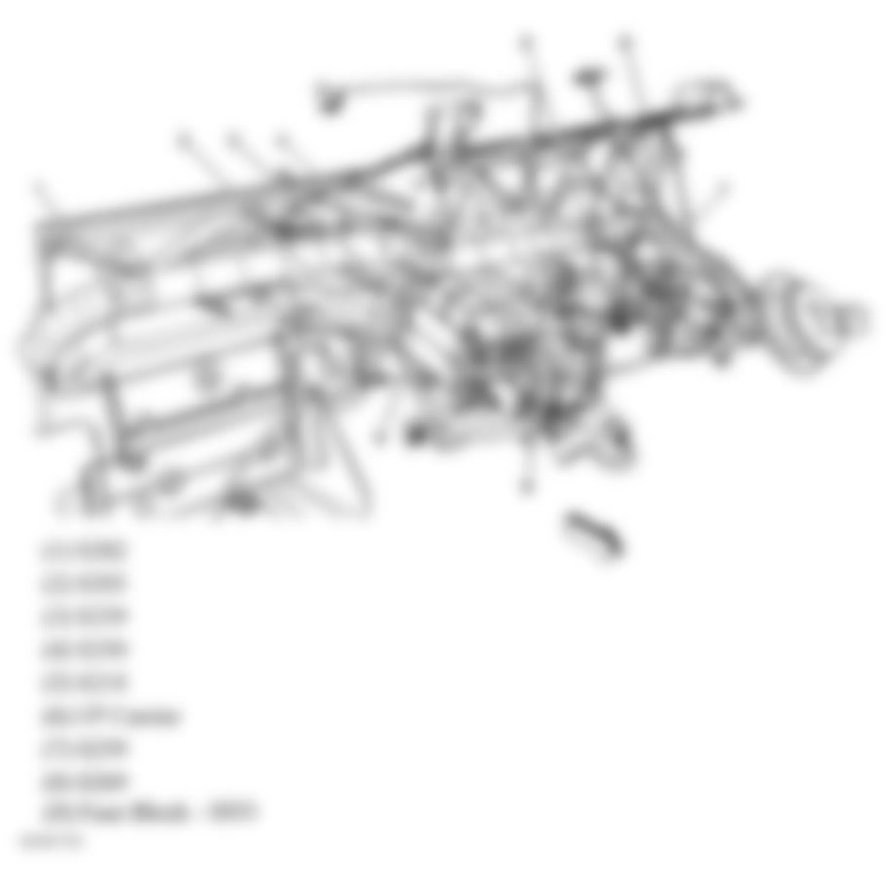
Fig. 64: Chevrolet Monte Carlo SS 2006 - Component Locations - Rear Of Dash
Fig. 65: Chevrolet Monte Carlo SS 2006 - Component Locations - Left Kick Panel
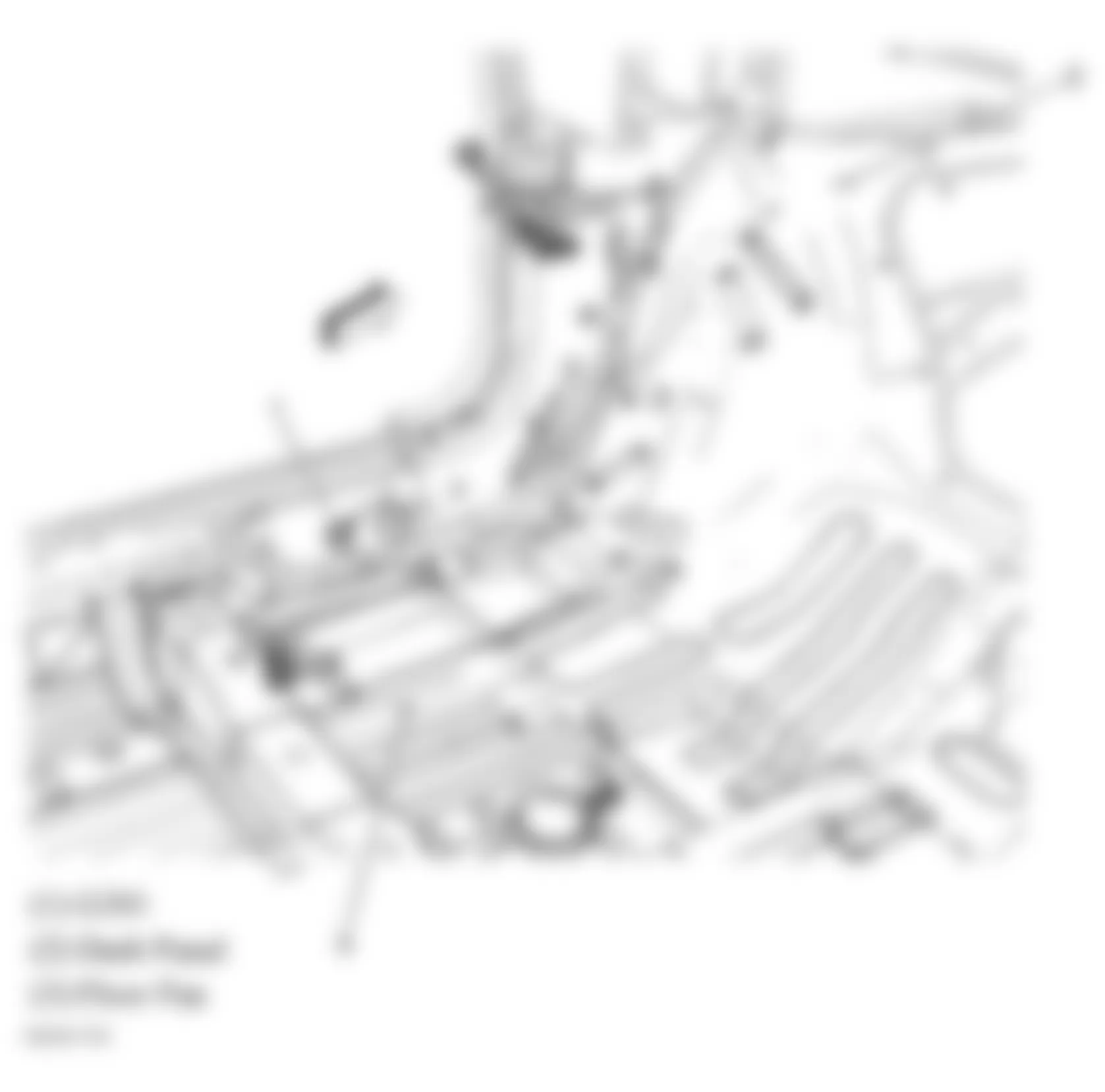
Fig. 66: Chevrolet Monte Carlo SS 2006 - Component Locations - Right Kick Panel
Fig. 67: Chevrolet Monte Carlo SS 2006 - Component Locations - Vehicle Overview
Fig. 68: Chevrolet Monte Carlo SS 2006 - Component Locations - Right "C" Pillar
Fig. 69: Chevrolet Monte Carlo SS 2006 - Component Locations - Underhood Fuse Block
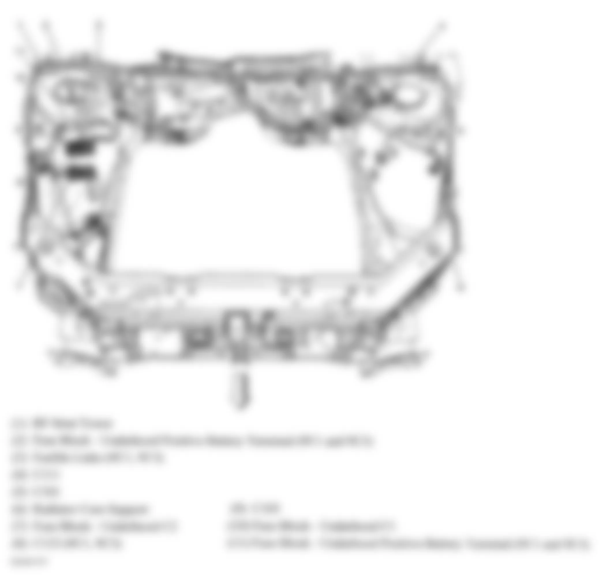
Fig. 70: Chevrolet Monte Carlo SS 2006 - Component Locations - Front Of Vehicle
Fig. 71: Chevrolet Monte Carlo SS 2006 - Component Locations - Right Front Of Engine Compartment
Fig. 72: Chevrolet Monte Carlo SS 2006 - Component Locations - Left Side Of Engine
Fig. 73: Chevrolet Monte Carlo SS 2006 - Component Locations - Right Rear Of Engine (5.3L)
Fig. 74: Chevrolet Monte Carlo SS 2006 - Component Locations - Left Side Of Engine
Fig. 75: Chevrolet Monte Carlo SS 2006 - Component Locations - Right Side Of Engine (3.5L & 3.9L)
Fig. 76: Chevrolet Monte Carlo SS 2006 - Component Locations - Left Side Of Dash
Fig. 77: Chevrolet Monte Carlo SS 2006 - Component Locations - Floor Pan (Sedan)
Fig. 78: Chevrolet Monte Carlo SS 2006 - Component Locations - Rear Of Passenger Compartment
Fig. 79: Chevrolet Monte Carlo SS 2006 - Component Locations - Rear Of Passenger Compartment
Fig. 80: Chevrolet Monte Carlo SS 2006 - Component Locations - Rear Shelf
Fig. 81: Chevrolet Monte Carlo SS 2006 - Component Locations - Rear Body Harness
Fig. 82: Chevrolet Monte Carlo SS 2006 - Component Locations - Driver's Door (Sedan)
Fig. 83: Chevrolet Monte Carlo SS 2006 - Component Locations - Front Passenger Door Harness (Sedan)
Fig. 84: Chevrolet Monte Carlo SS 2006 - Component Locations - Left Rear Door Harness (Sedan)
Fig. 85: Chevrolet Monte Carlo SS 2006 - Component Locations - Right Rear Door Harness (Sedan)
Fig. 86: Chevrolet Monte Carlo SS 2006 - Component Locations - Rear Compartment
Fig. 87: Chevrolet Monte Carlo SS 2006 - Component Locations - Deck Lid
Fig. 88: Chevrolet Monte Carlo SS 2006 - Component Locations - Rear Bumper (Sedan)
Fig. 89: Chevrolet Monte Carlo SS 2006 - Component Locations - Rear Bumper (Coupe)

