
Chevrolet SSR LS 2003 - 2003 ACCESSORIES & EQUIPMENT Wiring Systems (Electrical Components) - SSR
Chevrolet SSR LS 2003 - Component Locator Master Electrical Component List
Chevrolet SSR LS 2003 Master Electrical Component List
Name Location Locator View Connector End View 1-2 Shift Solenoid (1-2 SS) Valve In the automatic transmission Automatic Transmission Electronic Component Views in Automatic Transmission - 4L60-E/4L65-E Automatic Transmission Internal Connector End Views in Automatic Transmission - 4L60-E/4L65-E 2-3 Shift Solenoid (2-3 SS) Valve In the automatic transmission Automatic Transmission Electronic Component Views in Automatic Transmission - 4L60-E/4L65-E Automatic Transmission Internal Connector End Views in Automatic Transmission - 4L60-E/4L65-E 3-2 Shift Solenoid (3-2 SS) Valve In the automatic transmission Automatic Transmission Electronic Component Views in Automatic Transmission - 4L60-E/4L65-E Automatic Transmission Internal Connector End Views in Automatic Transmission - 4L60-E/4L65-E A/C Compressor Clutch Behind the A/C compressor pulley, part of the A/C compressor HVAC Component Views in HVAC Systems - Manual HVAC Connector End Views in HVAC Systems - Manual A/C Refrigerant Pressure Sensor On the high pressure hose connection to the compressor above thermo housing HVAC Component Views in HVAC Systems - Manual HVAC Connector End Views in HVAC Systems - Manual Accelerator Pedal Position (APP) Sensor Above the accelerator pedal assembly Engine Controls Component Views in Engine Controls - 5.3L Engine Controls Connector End Views in Engine Controls - 5.3L Air Temperature Actuator Behind radio on top of HVAC case HVAC Component Views in HVAC Systems - Manual HVAC Connector End Views in HVAC Systems - Manual Ambient Light Sensor Top center of I/P Lighting Systems Component Views in Lighting Systems Lighting Systems Connector End Views in Lighting Systems Audio Amplifier (Premium Radio) Rear center of body compartment behind seats near roof/door module Entertainment Component Views in Entertainment Entertainment Connector End Views in Entertainment Automatic Transmission Shift Lock Actuator Under center console at shift lever Automatic Transmission Shift Lock Control Component Views in Shift Lock Control Automatic Transmission Shift Lock Control Connector End Views in Shift Lock Control Automatic Transmission Fluid Pressure Manual Valve Position Switch In the automatic transmission Automatic Transmission Electronic Component Views in Automatic Transmission - 4L60-E/4L65-E Automatic Transmission Internal Connector End Views in Automatic Transmission - 4L60-E/4L65-E Auxiliary Gage (ERG/ERH) Under the center of the console Instrument Panel, Gages, and Console Component Views in Instrument Panel, Gages, and Console Instrument Panel, Gages, and Console Connector End Views in Instrument Panel, Gages, and Console Auxiliary Power Outlet - Front #1 In the right center of the I/P Power and Grounding Component Views Power and Grounding Connector End Views Auxiliary Power Outlet - Front #2 In the left center of the I/P Power and Grounding Component Views Power and Grounding Connector End Views Auxiliary Power Outlet - Rear In the right rear of rear compartment Power and Grounding Component Views Power and Grounding Connector End Views Backup Lamp - Left In the rear bumper at the left side of license plate Lighting Systems Component Views in Lighting Systems Lighting Systems Connector End Views in Lighting Systems Backup Lamp - Right In the rear bumper at the right side of license plate Lighting Systems Component Views in Lighting Systems Lighting Systems Connector End Views in Lighting Systems Battery Right rear of vehicle, near frame rail Engine Electrical Component Views in Engine Electrical Engine Electrical Connector End Views in Engine Electrical Blower Motor At the right lower I/P on the HVAC assembly HVAC Component Views in HVAC Systems - Manual HVAC Connector End Views in HVAC Systems - Manual Blower Motor Resistor Assembly At the right lower I/P on the HVAC assembly HVAC Component Views in HVAC Systems - Manual HVAC Connector End Views in HVAC Systems - Manual Body Control Module (BCM) Rear center of body compartment behind seats near relay block - rear Body Control System Component Views in Body Control System Body Control System Connector End Views in Body Control System Brake Fluid Level Switch On the left side of the brake fluid reservoir in the left rear of the engine compartment - - Camshaft Position (CMP) Sensor At the top center rear of the engine Engine Controls Component Views in Engine Controls - 5.3L Engine Controls Connector End Views in Engine Controls - 5.3L Center High Mounted Stop Lamp (CHMSL) On the top center of tailgate Lighting Systems Component Views in Lighting Systems Lighting Systems Connector End Views in Lighting Systems Center Console Switch Assembly In the center console between driver and passenger seat Power Door Systems Component Views in Doors Power Door Systems Connector End Views in Doors Cigar Lighter In the center of the I/P between the auxiliary power outlets Power and Grounding Component Views Power and Grounding Connector End Views Cooling Fan At the front center of engine Cooling System Component Views in Engine Cooling Cooling System Connector End Views in Engine Cooling Cooling Fan 1 Relay On the front left side of engine compartment Cooling System Component Views in Engine Cooling Cooling System Connector End Views in Engine Cooling Cooling Fan 2 Relay On the front left side of engine compartment Cooling System Component Views in Engine Cooling Cooling System Connector End Views in Engine Cooling Cruise Control Switch Part of the left-hand multifunction switch - - Crankshaft Position (CKP) Sensor At the lower right rear side of the engine block behind the starter solenoid Engine Controls Component Views in Engine Controls - 5.3L Engine Controls Connector End Views in Engine Controls - 5.3L Data Link Connector (DLC) On the lower left dash below the steering column Data Link Communications Component Views in Data Link Communications Data Link Communications Connector End Views in Data Link Communications Door Latch Assembly - Driver Inside driver door Power Door Systems Component Views in Doors Power Door Systems Connector End Views in Doors Door Latch Assembly - Passenger Inside passenger door Power Door Systems Component Views in Doors Power Door Systems Connector End Views in Doors Door Lock/Unlock Switch Part of the center console switch assembly - - Driver Window Switch Part of the center console switch assembly - - Electronic Brake Control Module (EBCM) On the left side of the inner frame rail under vehicle ABS Component Views in Antilock Brake System ABS Connector End Views in Antilock Brake System Electronic Frontal Sensor (EFS) - Left On the left underside of front frame crossmember, in back of grille SIR Component Views in SIR SIR Connector End Views in SIR Electronic Frontal Sensor (EFS) - Right On the right underside of the front frame crossmember, in back of grille SIR Component Views in SIR SIR Connector End Views in SIR Engine Coolant Temperature (ECT) Sensor Left cylinder head, on front of #1 exhaust port Engine Controls Component Views in Engine Controls - 5.3L Engine Controls Connector End Views in Engine Controls - 5.3L Engine Oil Pressure (EOP) Sensor At the top center rear of the engine Instrument Panel, Gages, and Console Component Views in Instrument Panel, Gages, and Console Instrument Panel, Gages, and Console Connector End Views in Instrument Panel, Gages, and Console Evaporative Emission (EVAP) Canister Purge Solenoid On top center of the engine, near the front Engine Controls Component Views in Engine Controls - 5.3L Engine Controls Connector End Views in Engine Controls - 5.3L Evaporative Emission (EVAP) Canister Vent Solenoid At the front right side of fuel tank Engine Controls Component Views in Engine Controls - 5.3L Engine Controls Connector End Views in Engine Controls - 5.3L Evaporator Temperature Sensor Behind radio on top of HVAC case, right of air temperature actuator HVAC Component Views in HVAC Systems - Manual HVAC Connector End Views in HVAC Systems - Manual Fog Lamp - LF In the left side of the front fascia Lighting Systems Component Views in Lighting Systems Lighting Systems Connector End Views in Lighting Systems Fog Lamp - RF In the right side of the front fascia Lighting Systems Component Views in Lighting Systems Lighting Systems Connector End Views in Lighting Systems Fuel Injector 1 On the left side of the intake manifold near the front of the engine at #1 cylinder Engine Controls Component Views in Engine Controls - 5.3L Engine Controls Connector End Views in Engine Controls - 5.3L Fuel Injector 2 On the right side of the intake manifold near the front of the engine at #2 cylinder Engine Controls Component Views in Engine Controls - 5.3L Engine Controls Connector End Views in Engine Controls - 5.3L Fuel Injector 3 On the left side of the intake manifold near the middle of the engine at #3 cylinder Engine Controls Component Views in Engine Controls - 5.3L Engine Controls Connector End Views in Engine Controls - 5.3L Fuel Injector 4 On the right side of the intake manifold near the middle of the engine at #4 cylinder Engine Controls Component Views in Engine Controls - 5.3L Engine Controls Connector End Views in Engine Controls - 5.3L Fuel Injector 5 On the left side of the intake manifold near the middle of the engine at #5 cylinder Engine Controls Component Views in Engine Controls - 5.3L Engine Controls Connector End Views in Engine Controls - 5.3L Fuel Injector 6 On the right side of the intake manifold near the middle of the engine at #6 cylinder Engine Controls Component Views in Engine Controls - 5.3L Engine Controls Connector End Views in Engine Controls - 5.3L Fuel Injector 7 On the left side of the intake manifold near the rear of the engine at #7 cylinder Engine Controls Component Views in Engine Controls - 5.3L Engine Controls Connector End Views in Engine Controls - 5.3L Fuel Injector 8 On the right side of the intake manifold near the rear of the engine at #8 cylinder Engine Controls Component Views in Engine Controls - 5.3L Engine Controls Connector End Views in Engine Controls - 5.3L Fuel Pump and Sender Assembly In the fuel tank, center top Instrument Panel, Gages, and Console Component Views in Instrument Panel, Gages, and Console Instrument Panel, Gages, and Console Connector End Views in Instrument Panel, Gages, and Console Fuel Tank Pressure (FTP) Sensor On the rear top of fuel tank Engine Controls Component Views in Engine Controls - 5.3L Engine Controls Connector End Views in Engine Controls - 5.3L Fuse Block - Rear Rear center of body compartment behind seats near relay block - rear Power and Grounding Component Views Electrical Center Identification Views Fuse Block - Underhood At the left front side of the engine compartment Power and Grounding Component Views Electrical Center Identification Views Generator At the left front of engine Engine Electrical Component Views in Engine Electrical Engine Electrical Connector End Views in Engine Electrical Hazard Switch Part of turn signal/multifunction switch - - Headlamp - High Beam - Left On the left front of vehicle Lighting Systems Component Views in Lighting Systems Lighting Systems Connector End Views in Lighting Systems Headlamp - High Beam - Right On the right front of vehicle Lighting Systems Component Views in Lighting Systems Lighting Systems Connector End Views in Lighting Systems Headlamp - Low Beam - Left On the left front of vehicle Lighting Systems Component Views in Lighting Systems Lighting Systems Connector End Views in Lighting Systems Headlamp - Low Beam - Right On the right front of vehicle Lighting Systems Component Views in Lighting Systems Lighting Systems Connector End Views in Lighting Systems Headlamp Switch On the left side of I/P Lighting Systems Component Views in Lighting Systems Lighting Systems Connector End Views in Lighting Systems Heated Oxygen Sensor (HO2S) Bank 1 Sensor 1 In the left bank exhaust pipe, ahead of the catalytic converter Engine Controls Component Views in Engine Controls - 5.3L Engine Controls Connector End Views in Engine Controls - 5.3L Heated Oxygen Sensor (HO2S) Bank 1 Sensor 2 In the left bank exhaust pipe, behind the catalytic converter Engine Controls Component Views in Engine Controls - 5.3L Engine Controls Connector End Views in Engine Controls - 5.3L Heated Oxygen Sensor (HO2S) Bank 2 Sensor 1 In the right bank exhaust pipe, ahead of the catalytic converter Engine Controls Component Views in Engine Controls - 5.3L Engine Controls Connector End Views in Engine Controls - 5.3L Heated Oxygen Sensor (HO2S) Bank 2 Sensor 2 In the right bank exhaust pipe, behind the catalytic converter Engine Controls Component Views in Engine Controls - 5.3L Engine Controls Connector End Views in Engine Controls - 5.3L Heated Seat Element - Driver Cushion In cushion seat of driver seat Power Seat Systems Component Views in Seats Power Seat Systems Connector End Views in Seats Heated Seat Element - Driver Back In seat back of driver seat Power Seat Systems Component Views in Seats Power Seat Systems Connector End Views in Seats Heated Seat Element - Passenger Cushion In cushion seat of passenger seat Power Seat Systems Component Views in Seats Power Seat Systems Connector End Views in Seats Heated Seat Element - Passenger Back In seat back of passenger seat Power Seat Systems Component Views in Seats Power Seat Systems Connector End Views in Seats Heated Seat Switch - Driver On lower left side of driver seat Power Seat Systems Component Views in Seats Power Seat Systems Connector End Views in Seats Heated Seat Switch - Passenger On lower Right side of passenger seat Power Seat Systems Component Views in Seats Power Seat Systems Connector End Views in Seats Horn Assembly At the left front side of the engine compartment, in back of left front headlamp Horns Component Views in Horns Horns Connector End Views in Horns HVAC Control Module In the center of the I/P HVAC Component Views in HVAC Systems - Manual HVAC Connector End Views in HVAC Systems - Manual Ignition Coil 1 On the left rocker cover near the front of the engine at #1 cylinder Engine Controls Component Views in Engine Controls - 5.3L Engine Controls Connector End Views in Engine Controls - 5.3L Ignition Coil 2 On the right rocker cover near the front of the engine at #2 cylinder Engine Controls Component Views in Engine Controls - 5.3L Engine Controls Connector End Views in Engine Controls - 5.3L Ignition Coil 3 On the left rocker cover near the middle of the engine at #3 cylinder Engine Controls Component Views in Engine Controls - 5.3L Engine Controls Connector End Views in Engine Controls - 5.3L Ignition Coil 4 On the right rocker cover near the middle of the engine at #4 cylinder Engine Controls Component Views in Engine Controls - 5.3L Engine Controls Connector End Views in Engine Controls - 5.3L Ignition Coil 5 On the left rocker cover near the middle of the engine at #5 cylinder Engine Controls Component Views in Engine Controls - 5.3L Engine Controls Connector End Views in Engine Controls - 5.3L Ignition Coil 6 On the right rocker cover near the middle of the engine at #6 cylinder Engine Controls Component Views in Engine Controls - 5.3L Engine Controls Connector End Views in Engine Controls - 5.3L Ignition Coil 7 On the right rocker cover near the rear of the engine at #7 cylinder Engine Controls Component Views in Engine Controls - 5.3L Engine Controls Connector End Views in Engine Controls - 5.3L Ignition Coil 8 On the left rocker cover near the rear of the engine at #8 cylinder Engine Controls Component Views in Engine Controls - 5.3L Engine Controls Connector End Views in Engine Controls - 5.3L Ignition Key Alarm Switch In steering column in ignition cylinder housing Instrument Panel, Gages, and Console Component Views in Instrument Panel, Gages, and Console Instrument Panel, Gages, and Console Connector End Views in Instrument Panel, Gages, and Console Ignition Lock Cylinder Control Actuator On the right side of steering column Steering Wheel and Column Component Views in Steering Wheel and Column Steering Wheel and Column Connector End Views in Steering Wheel and Column Ignition Switch In the upper steering column, under lower cover Power and Grounding Component Views Power and Grounding Connector End Views I/P Compartment Lamp Right side of I/P in compartment box Lighting Systems Component Views in Lighting Systems Lighting Systems Connector End Views in Lighting Systems Inflatable Restraint I/P Module Right side of I/P, above I/P compartment box SIR Component Views in SIR SIR Connector End Views in SIR Inflatable Restraint I/P Module Disable Switch Left side of I/P in compartment box SIR Component Views in SIR SIR Connector End Views in SIR Inflatable Restraint Seat Position Sensor (SPS) - Left Under left seat bottom on track SIR Component Views in SIR SIR Connector End Views in SIR Inflatable Restraint Seat Position Sensor (SPS) - Right Under passenger seat SIR Component Views in SIR SIR Connector End Views in SIR Inflatable Restraint Sensing and Diagnostic Module (SDM) Beneath the lower console SIR Component Views in SIR SIR Connector End Views in SIR Inflatable Restraint Side Impact Module - Left Inside driver seat back SIR Component Views in SIR SIR Connector End Views in SIR Inflatable Restraint Side Impact Module - Right Inside passenger seat back SIR Component Views in SIR SIR Connector End Views in SIR Inflatable Restraint Side Impact Sensor (SIS) - Left Inside driver door SIR Component Views in SIR SIR Connector End Views in SIR Inflatable Restraint Side Impact Sensor (SIS) - Right Inside passenger door SIR Component Views in SIR SIR Connector End Views in SIR Inflatable Restraint Steering Wheel Module Coil In center of steering column, under steering wheel SIR Component Views in SIR SIR Connector End Views in SIR Inflatable Restraint Passenger Air Bag ON/OFF Indicator In the header above the inside rearview mirror SIR Component Views in SIR SIR Connector End Views in SIR Inside Rearview Mirror (W/O DJ2) Mounted to the windshield at the top center of the window Lighting Systems Component Views in Lighting Systems Lighting Systems Connector End Views in Lighting Systems Inside Rearview Mirror (W/DJ2) Mounted tor the windshield at the top center of the window Lighting Systems Component Views in Lighting Systems Lighting Systems Connector End Views in Lighting Systems Instrument Panel Cluster (IPC) On the left side of the I/P above the steering column Instrument Panel, Gages, and Console Component Views in Instrument Panel, Gages, and Console Instrument Panel, Gages, and Console Connector End Views in Instrument Panel, Gages, and Console Intake Air Temperature (IAT) - Mass Air Flow (MAF) Sensor Part of the air induction system between the air cleaner assembly and the throttle body Engine Controls Component Views in Engine Controls - 5.3L Engine Controls Connector End Views in Engine Controls - 5.3L Junction Block - Underhood On right front side of engine compartment - - Knock Sensor (KS) 1 On the top front center of engine Engine Controls Component Views in Engine Controls - 5.3L Engine Controls Connector End Views in Engine Controls - 5.3L Knock Sensor (KS) 2 On the top rear center of engine Engine Controls Component Views in Engine Controls - 5.3L Engine Controls Connector End Views in Engine Controls - 5.3L License Lamp - Left At the center of the rear bumper Lighting Systems Component Views in Lighting Systems Lighting Systems Connector End Views in Lighting Systems License Lamp - Right At the center of the rear bumper Lighting Systems Component Views in Lighting Systems Lighting Systems Connector End Views in Lighting Systems Lumbar Motor - Driver In driver seat back Power Seat Systems Component Views in Seats Power Seat Systems Connector End Views in Seats Lumbar Motor - Passenger In passenger seat back Power Seat Systems Component Views in Seats Power Seat Systems Connector End Views in Seats Manifold Absolute Pressure (MAP) Top rear center of the engine on the intake manifold Engine Controls Component Views in Engine Controls - 5.3L Engine Controls Connector End Views in Engine Controls - 5.3L Marker Lamp - LF Left front fender, front of wheel opening Lighting Systems Component Views in Lighting Systems Lighting Systems Connector End Views in Lighting Systems Marker Lamp - LR Left rear quarter panel, rear of wheel opening Lighting Systems Component Views in Lighting Systems Lighting Systems Connector End Views in Lighting Systems Marker Lamp - RF Right front fender, front of wheel opening Lighting Systems Component Views in Lighting Systems Lighting Systems Connector End Views in Lighting Systems Marker Lamp - RR Right rear quarter panel, rear of wheel opening Lighting Systems Component Views in Lighting Systems Lighting Systems Connector End Views in Lighting Systems Memory Seat Module - Driver Under driver seat Power Seat Systems Component Views in Seats Power Seat Systems Connector End Views in Seats Mode Actuator Left side of I/P area above accelerator pedal on HVAC case HVAC Component Views in HVAC Systems - Manual HVAC Connector End Views in HVAC Systems - Manual Noise Compensation Microphone In left lower knee bolster Entertainment Component Views in Entertainment Entertainment Connector End Views in Entertainment Outside Rearview Mirror - Driver Attached to the outside left front driver door Power Door Systems Component Views in Doors Power Door Systems Connector End Views in Doors Outside Rearview Mirror - Passenger Attached to the outside left front passenger door Power Door Systems Component Views in Doors Power Door Systems Connector End Views in Doors Outside Rearview Mirror Switch On the left door trim panel armrest Power Door Systems Component Views in Doors Power Door Systems Connector End Views in Doors Passlock Sensor In upper steering column in ignition key cylinder housing Steering Wheel and Column Component Views in Steering Wheel and Column - Park Brake Switch In the center console between driver and passenger seat attached to park brake - - Park/Neutral Position (PNP) Switch On lower left side of the automatic transmission Automatic Transmission Electronic Component Views in Automatic Transmission - 4L60-E/4L65-E Automatic Transmission Related Connector End Views in Automatic Transmission - 4L60-E/4L65-E Park/Turn Signal Lamp - LF On the left front of vehicle Lighting Systems Component Views in Lighting Systems Lighting Systems Connector End Views in Lighting Systems Park/Turn Signal Lamp - RF On the right front of vehicle Lighting Systems Component Views in Lighting Systems Lighting Systems Connector End Views in Lighting Systems Passlock Sensor In upper steering column in ignition key cylinder housing Steering Wheel and Column Component Views in Steering Wheel and Column - Passenger Window Switch Part of the center console switch assembly - - Position Sensor - Front On driver seat motor Power Seat Systems Component Views in Seats Power Seat Systems Connector End Views in Seats Position Sensor - Horizontal On driver seat motor Power Seat Systems Component Views in Seats Power Seat Systems Connector End Views in Seats Position Sensor - Rear On driver seat motor Power Seat Systems Component Views in Seats Power Seat Systems Connector End Views in Seats Powertrain Control Module (PCM) At the left front side of the engine compartment Engine Controls Component Views in Engine Controls - 5.3L Powertrain Control Module (PCM) Connector End Views in Engine Controls - 5.3L Pressure Control (PC) Solenoid Valve In the automatic transmission Automatic Transmission Electronic Component Views in Automatic Transmission - 4L60-E/4L65-E Automatic Transmission Internal Connector End Views in Automatic Transmission - 4L60-E/4L65-E Radio In the center of the I/P Entertainment Component Views in Entertainment Entertainment Connector End Views in Entertainment Radio Antenna Module At the top center of the windshield right visor Entertainment Component Views in Entertainment Entertainment Connector End Views in Entertainment Rear Compartment Ajar Switch In the rear compartment left rear latch Body Rear End Component Views in Body Rear End Body Rear End Connector End Views in Body Rear End Rear Compartment Lid Lamp (SEO) In the rear compartment lid Lighting Systems Component Views in Lighting Systems Lighting Systems Connector End Views in Lighting Systems Rear Compartment Lid Release Switch/Actuator - Exterior Under left rear of the vehicle, on left frame rail Body Rear End Component Views in Body Rear End Body Rear End Connector End Views in Body Rear End Rear Compartment Lid Release Switch - Interior Left side of I/P in compartment box Body Rear End Component Views in Body Rear End Body Rear End Connector End Views in Body Rear End Rear Compartment Present Switch In the rear compartment left rear hinge Body Rear End Component Views in Body Rear End Body Rear End Connector End Views in Body Rear End Rear Window Defogger Grid In rear window Stationary Windows Component Views in Stationary Windows Stationary Windows Connector End Views in Stationary Windows Recirculation Actuator In back of I/P right side, above blower motor on HVAC case HVAC Component Views in HVAC Systems - Manual HVAC Connector End Views in HVAC Systems - Manual Relay Block - Rear Rear center of body compartment behind seats near roof/door module Power and Grounding Component Views Electrical Center Identification Views Remote Control Door Lock Receiver (RCDLR) Between seat backs above BCM Keyless Entry Component Views in Keyless Entry Keyless Entry Connector End Views in Keyless Entry Retractable Roof Motor Left Relay Behind seats near roof door module, attached to pump motor Power Roof Systems Component Views in Roof Power Roof Systems Connector End Views in Roof Retractable Roof Motor Right Relay Behind seats near roof door module, attached to pump motor Power Roof Systems Component Views in Roof Power Roof Systems Connector End Views in Roof Retractable Roof Panel Outer Latch Actuator In center of header, above inside rearview mirror Power Roof Systems Component Views in Roof Power Roof Systems Connector End Views in Roof Retractable Roof Panel Outer Latch Position Switch In header, above left visor Power Roof Systems Component Views in Roof Power Roof Systems Connector End Views in Roof Retractable Roof Panel Outer Latch Striker Position Switch In header center, attached to actuator Power Roof Systems Component Views in Roof Power Roof Systems Connector End Views in Roof Retractable Roof Position Sensor Lower right B-pillar on retractable roof position cylinder Power Roof Systems Component Views in Roof Power Roof Systems Connector End Views in Roof Retractable Roof Pump Motor Between seats in roof stowage compartment center bottom Power Roof Systems Component Views in Roof Power Roof Systems Connector End Views in Roof Retractable Roof Pump/Valve Assembly Between seats in roof storage area, bottom center Power Roof Systems Component Views in Roof Power Roof Systems Connector End Views in Roof Retractable Roof Stowage Compartment Closeout Panel Position Sensor - Extended/Retracted On stowage compartment closeout cylinder, right side Power Roof Systems Component Views in Roof Power Roof Systems Connector End Views in Roof Retractable Roof Stowage Compartment Lid Position Sensor On roof cover right side stowage compartment lid cylinder Power Roof Systems Component Views in Roof Power Roof Systems Connector End Views in Roof Retractable Roof Stowage Compartment Position Sensor - Left On stowage compartment position left cylinder in B-pillar Power Roof Systems Component Views in Roof Power Roof Systems Connector End Views in Roof Retractable Roof Stowage Compartment Position Sensor - Right On stowage compartment position right cylinder in B-pillar Power Roof Systems Component Views in Roof Power Roof Systems Connector End Views in Roof Retractable Roof Stowage Compartment Lid Sensor - Left Behind B-pillar on stowage compartment lid left cylinder, on upper bracket Power Roof Systems Component Views in Roof Power Roof Systems Connector End Views in Roof Retractable Roof Stowage Compartment Lid Sensor - Right Behind B-pillar on stowage compartment lid right cylinder, on upper bracket Power Roof Systems Component Views in Roof Power Roof Systems Connector End Views in Roof Retractable Roof Switch Part of center console switch assembly - - Retractable Roof Valve 1 Part of retractable roof pump/valve assembly Power Roof Systems Component Views in Roof Power Roof Systems Connector End Views in Roof Retractable Roof Valve 2 Part of retractable roof pump/valve assembly Power Roof Systems Component Views in Roof Power Roof Systems Connector End Views in Roof Retractable Roof Valve 3 Part of retractable roof pump/valve assembly Power Roof Systems Component Views in Roof Power Roof Systems Connector End Views in Roof Retractable Roof Valve 4 Part of retractable roof pump/valve assembly Power Roof Systems Component Views in Roof Power Roof Systems Connector End Views in Roof Roof/Door Module Rear center of body compartment behind seats near relay block - rear Power Roof Systems Component Views in Roof Power Roof Systems Connector End Views in Roof Seat Adjuster Switch - Driver On the left side of the driver seat Power Seat Systems Component Views in Seats Power Seat Systems Connector End Views in Seats Seat Adjuster Switch - Passenger On the right side of the passenger seat Power Seat Systems Component Views in Seats Power Seat Systems Connector End Views in Seats Seat Belt Switch - Driver In the driver seat belt buckle Seat Belt Component Views in Seat Belts Seat Belt Connector End Views in Seat Belts Seat Belt Switch - Passenger In the passenger seat belt buckle Power Seat Systems Component Views in Seats Power Seat Systems Connector End Views in Seats Seat Belt Pretensioner - Left At the left inner B-pillar SIR Component Views in SIR SIR Connector End Views in SIR Seat Belt Pretensioner - Right At the right inner B-pillar SIR Component Views in SIR SIR Connector End Views in SIR Seat Front Vertical Motor - Driver Part of seat motors assembly - driver, on seat frame of driver seat - - Seat Horizontal Motor - Driver Part of seat motors assembly - driver, on seat frame of driver seat - - Seat Horizontal Motor - Passenger Part of seat motors assembly - passenger, on seat frame of passenger seat - - Seat Motors Assembly - Driver On seat frame of driver seat Power Seat Systems Component Views in Seats Power Seat Systems Connector End Views in Seats Seat Motors Assembly - Passenger On seat frame of passenger seat Power Seat Systems Component Views in Seats Power Seat Systems Connector End Views in Seats Seat Rear Vertical Motor - Driver Part of seat motors assembly - driver, on seat frame of driver seat - - Speaker - LF Door On the left front door trim panel Entertainment Component Views in Entertainment Entertainment Connector End Views in Entertainment Speaker - LF Door Midrange (Premium Radio) On the left front door trim panel Entertainment Component Views in Entertainment Entertainment Connector End Views in Entertainment Speaker - LF Door Tweeter (Base Radio) On the left front door trim panel Entertainment Component Views in Entertainment Entertainment Connector End Views in Entertainment Speaker - LR Behind driver seat left rear of body compartment Entertainment Component Views in Entertainment Entertainment Connector End Views in Entertainment Speaker - RF Door On the right front door trim panel Entertainment Component Views in Entertainment Entertainment Connector End Views in Entertainment Speaker - RF Door Midrange (Premium Radio) On the right front door trim panel Entertainment Component Views in Entertainment Entertainment Connector End Views in Entertainment Speaker - RF Door Tweeter (Base Radio) On the right front door trim panel Entertainment Component Views in Entertainment Entertainment Connector End Views in Entertainment Speaker - RR Behind passenger seat right rear of body compartment Entertainment Component Views in Entertainment Entertainment Connector End Views in Entertainment Starter On the left side of engine near the front Engine Electrical Component Views in Engine Electrical - Stop Lamp Switch At the top of the brake pedal assembly Lighting Systems Component Views in Lighting Systems Lighting Systems Connector End Views in Lighting Systems Steering Wheel Control Assembly On steering wheel Entertainment Component Views in Entertainment Entertainment Connector End Views in Entertainment Steering Wheel Controls - Left Part of steering wheel control assembly Entertainment Component Views in Entertainment Entertainment Connector End Views in Entertainment Steering Wheel Controls - Right Part of steering wheel control assembly Entertainment Component Views in Entertainment Entertainment Connector End Views in Entertainment Tail/Stop and Turn Signal Lamp - Left On the left rear of vehicle Lighting Systems Component Views in Lighting Systems Lighting Systems Connector End Views in Lighting Systems Tail/Stop and Turn Signal Lamp - Right On the right rear of vehicle Lighting Systems Component Views in Lighting Systems Lighting Systems Connector End Views in Lighting Systems Throttle Actuator Control (TAC) Module At the left rear of engine compartment Engine Controls Component Views in Engine Controls - 5.3L Engine Controls Connector End Views in Engine Controls - 5.3L Throttle Body Front center top of engine Engine Controls Component Views in Engine Controls - 5.3L Engine Controls Connector End Views in Engine Controls - 5.3L Torque Converter Clutch (TCC) Solenoid Valve In the automatic transmission Automatic Transmission Electronic Component Views in Automatic Transmission - 4L60-E/4L65-E Automatic Transmission Internal Connector End Views in Automatic Transmission - 4L60-E/4L65-E Torque Converter Clutch Pulse Width Modulation (TCC PWM) Solenoid Valve In the automatic transmission Automatic Transmission Electronic Component Views in Automatic Transmission - 4L60-E/4L65-E Automatic Transmission Internal Connector End Views in Automatic Transmission - 4L60-E/4L65-E Traction On/Off Switch Part of the center console switch assembly - - Turn Signal/Hazard Flasher Module In the left side of the I/P, on lower knee bolster Lighting Systems Component Views in Lighting Systems Lighting Systems Connector End Views in Lighting Systems Turn Switch Part of turn signal/multifunction switch - - Trailer Tow (Blunt Cut) At the rear of the vehicle below the rear bumper Lighting Systems Component Views in Lighting Systems - Turn Signal/Multifunction Switch On left side of steering column Lighting Systems Component Views in Lighting Systems Lighting Systems Connector End Views in Lighting Systems Vanity Mirror Lamp - LF On the headliner above the driver Lighting Systems Component Views in Lighting Systems Lighting Systems Connector End Views in Lighting Systems Vanity Mirror Lamp - RF On the headliner above the passenger Lighting Systems Component Views in Lighting Systems Lighting Systems Connector End Views in Lighting Systems Vehicle Speed Sensor (VSS) On the right rear of the automatic transmission Automatic Transmission Electronic Component Views in Automatic Transmission - 4L60-E/4L65-E Automatic Transmission Related Connector End Views in Automatic Transmission - 4L60-E/4L65-E Wheel Speed Sensor (WSS) - LF On the left front hub and bearing assembly ABS Component Views in Antilock Brake System ABS Connector End Views in Antilock Brake System Wheel Speed Sensor (WSS) - RF On the right front hub and bearing assembly ABS Component Views in Antilock Brake System ABS Connector End Views in Antilock Brake System Window Motor - Driver In the driver door Power Door Systems Component Views in Doors Power Door Systems Connector End Views in Doors Window Motor - Passenger In the passenger door Power Door Systems Component Views in Doors Power Door Systems Connector End Views in Doors Windshield Washer Fluid Pump Mounted on the fluid reservoir in the underhood compartment Wiper/Washer System Component Views in Wiper/Washer Systems Wiper/Washer System Connector End Views in Wiper/Washer Systems Windshield Wiper Motor Near the center of the front cowling Wiper/Washer System Component Views in Wiper/Washer Systems Wiper/Washer System Connector End Views in Wiper/Washer Systems Windshield Wiper/Washer Switch Part of the turn signal/multifunction switch - - C100 (38 cavities) In engine harness to I/P harness, at the left rear side of engine compartment Harness Routing Views Inline Harness Connector End Views C103 (10 cavities) In front lamp harness to I/P harness, at the left front of vehicle under bumper fascia clipped on frame Harness Routing Views Inline Harness Connector End Views C104 (16 cavities) In front fascia harness to front lamp harness, in left side rear of engine compartment near master cylinder Harness Routing Views Inline Harness Connector End Views C105 (38 cavities) In chassis harness to I/P harness, at the left side of engine compartment near the frame rail Harness Routing Views Inline Harness Connector End Views C108 (7 cavities) Coils harness to engine harness, on top of the right bank valve cover Harness Routing Views Inline Harness Connector End Views C109 (7 cavities) Coils harness to engine harness, on top of the left bank valve cover Harness Routing Views Inline Harness Connector End Views C115 (2 cavities) In engine harness to knock sensor, on top of engine center rear Harness Routing Views Inline Harness Connector End Views C175 (13 cavities) Engine harness to the automatic transmission harness, at the right side of the automatic transmission case Harness Routing Views Inline Harness Connector End Views C200 (4 cavities) In body harness to I/P harness, rear center of the body compartment behind seats, near fuse block - rear Harness Routing Views Inline Harness Connector End Views C201 (48 cavities) Steering column harness to I/P harness, at the base of the steering column Harness Routing Views Inline Harness Connector End Views C202 (30 cavities) In body harness to I/P harness, behind passenger seat and under carpet, near fuse block - rear Harness Routing Views Inline Harness Connector End Views C204 (30 cavities) In body harness to I/P harness, behind passenger seat and under carpet, near fuse block - rear Harness Routing Views Inline Harness Connector End Views C205 (2 cavities) In I/P harness to cigar lighter jumper harness, in the center of the I/P Harness Routing Views Inline Harness Connector End Views C300 (16 cavities) In I/P harness to driver seat harness, under driver seat Harness Routing Views Inline Harness Connector End Views C303 (18 cavities) In body harness to header harness, on the right side of the passenger compartment behind the right kick panel Harness Routing Views Inline Harness Connector End Views C304 (2 cavities) In header harness to PSIR jumper harness in the right front side header Harness Routing Views Inline Harness Connector End Views C306 (16 cavities) In body harness to passenger seat, under passenger seat Harness Routing Views Inline Harness Connector End Views C308 (4 cavities) In body harness to roof harness, under right rear speaker Harness Routing Views Inline Harness Connector End Views C309 (6 cavities) In body harness to roof harness, under right rear speaker Harness Routing Views Inline Harness Connector End Views C310 (4 cavities) In retractable roof harness to roof pump harness, near pump valve manifold Harness Routing Views Inline Harness Connector End Views C313 (6 cavities) In driver seat harness to seat motor harness, under driver seat Harness Routing Views Inline Harness Connector End Views C314 (6 cavities) In passenger seat harness to seat motor harness, under passenger seat Harness Routing Views Inline Harness Connector End Views C400 (2 cavities) In chassis harness to rear fascia harness, above left rear frame rail and trailer hitch, on the left rear of vehicle Harness Routing Views Inline Harness Connector End Views C401 (6 cavities) In chassis harness to tailgate harness, clipped on frame rail, on the left rear of vehicle Harness Routing Views Inline Harness Connector End Views C402 (2 cavities) In chassis harness to auxiliary power outlet harness, on the right rear of vehicle on frame rail Harness Routing Views Inline Harness Connector End Views C404 (4 cavities) In chassis harness to bed cover harness, clipped on frame rail, on the left rear of vehicle Harness Routing Views Inline Harness Connector End Views C500 (18 cavities) In I/P harness to driver door harness, under the left kick panel Harness Routing Views Inline Harness Connector End Views C501 (10 cavities) In I/P harness to driver door harness, under the left kick panel Harness Routing Views Inline Harness Connector End Views C600 (18 cavities) In body harness to passenger door harness, under the right kick panel Harness Routing Views Inline Harness Connector End Views C601 (10 cavities) In body harness to passenger door harness, under the right kick panel Harness Routing Views Inline Harness Connector End Views D300 Rear center of body compartment behind seats near relay block - rear Harness Routing Views Lighting Systems Connector End Views in Lighting Systems G100 At the left front of engine Power and Grounding Component Views - G101 At the left front of engine Power and Grounding Component Views - G102 At the left rear of engine Power and Grounding Component Views - G103 At the left rear of the engine compartment on the cowl Power and Grounding Component Views - G105 At the left front of engine compartment, behind cooling fan relay Power and Grounding Component Views - G200 Ground splice pack, right of cluster in back of I/P below radio Power and Grounding Component Views - G300 On lower left B-pillar floor Power and Grounding Component Views - G301 Behind right rear passenger seat track near B-pillar floor Power and Grounding Component Views - G302 Under console at rear below fuse block - rear, center on floor board Power and Grounding Component Views - G400 On the left front frame body mount Power and Grounding Component Views - G401 On the left middle frame body mount Power and Grounding Component Views - G402 On the left rear frame body mount Power and Grounding Component Views - G404 On the right rear frame body mount, from battery to body Power and Grounding Component Views - G405 On the right rear frame body mount, from battery to frame Power and Grounding Component Views - S100 In engine harness, approximately 7.5 cm (2.95 in) from fuel injector breakout Harness Routing Views - S101 In engine harness, approximately 18.5 cm (7.2 in) from powertrain control module breakout Harness Routing Views - S102 In engine harness, approximately 11 cm (4.3 in) from manifold absolute pressure sensor breakout Harness Routing Views - S103 In front lamp harness, approximately 8 cm (3.14 in) from headlamp breakout Harness Routing Views - S104 In front lamp harness, approximately 8 cm (3.14 in) from cooling fan breakout Harness Routing Views - S105 In front lamp harness, approximately 2.5 cm (0.98 in) from cooling fan relay breakout Harness Routing Views - S106 In front lamp harness, approximately 5 cm (1.96 in) from cooling fan relay breakout Harness Routing Views - S107 In ignition coil harness Harness Routing Views - S108 In ignition coil harness Harness Routing Views - S109 In ignition coil harness Harness Routing Views - S110 In ignition coil harness Harness Routing Views - S111 In front lamp harness, approximately 5 cm (1.96 in) from horn assembly breakout Harness Routing Views - S113 In the battery positive cable harness, approximately 31 cm (12.20 in) from starter Harness Routing Views - S118 In ignition coil harness Harness Routing Views - S119 In ignition coil harness Harness Routing Views - S200 In I/P harness, approximately 44 cm (17.3 in) from driver door inline breakout Harness Routing Views - S133 In transmission harness Harness Routing Views - S202 In I/P harness, approximately 95 cm (37.4 in) from driver door inline breakout Harness Routing Views - S203 In I/P harness, approximately 22 cm (8.6 in) from driver door inline breakout Harness Routing Views - S205 In I/P harness, approximately 17.2 cm (6.7 in) from steering column inline breakout Harness Routing Views - S206 In I/P harness, approximately 30 cm (11.8 in) from steering column inline breakout Harness Routing Views - S207 In I/P harness, approximately 9 cm (3.5 in) from HVAC control module breakout Harness Routing Views - S208 In I/P harness, approximately 5 cm (3.5 in) from HVAC control module breakout Harness Routing Views - S209 In I/P harness, approximately 15 cm (5.9 in) from HVAC control module breakout Harness Routing Views - S226 In steering column harness Harness Routing Views - S227 In steering column harness, approximately 30 cm (11.8 in) from steering column inline breakout Harness Routing Views - S300 In I/P harness, approximately 7 cm (2.7 in) from body control module C5 breakout Harness Routing Views - S301 In body harness, approximately 10 cm (3.9 in) from fuse block - rear breakout Harness Routing Views - S302 In body harness, approximately 18.2 cm (7 in) from fuse block - rear breakout Harness Routing Views - S303 In body harness, approximately 34.5 cm (13.5 in) from seat belt pretensioner - RF breakout Harness Routing Views - S304 In header harness, approximately 19 cm (7.4 in) from radio antenna module breakout Harness Routing Views - S306 In body harness, approximately 3.2 cm (1.25 in) from fuse block - rear breakout Harness Routing Views - S307 In driver seat harness, approximately 4 cm (1.5 in) from the seat adjuster switch breakout Harness Routing Views - S308 In passenger harness, approximately 4 cm (1.5 in) from passenger seat motor breakout Harness Routing Views - S309 In passenger harness, approximately 6 cm (2.3 in) from seat belt switch breakout Harness Routing Views - S310 In retractable roof harness, approximately 47 cm (18.5 in) from grommet, near inline to body harness Harness Routing Views - S311 In retractable roof harness, approximately 94 cm (18.5 in) from pump relay breakout Harness Routing Views - S312 In retractable roof harness, approximately 99 cm (38.9 in) from pump relay breakout Harness Routing Views - S313 In driver seat harness, approximately 4 cm (1.5 in) from the seat adjuster switch breakout Harness Routing Views - S314 In retractable roof harness Harness Routing Views - S315 In driver seat harness, approximately 2.5 cm (0.9 in) from memory seat module - driver C1, C3 breakout Harness Routing Views - S316 In retractable roof harness, approximately 57 cm (22.4 in) from grommet, near inlines to body harness Harness Routing Views - S317 In retractable roof harness, approximately 27 cm (10.6 in) from grommet, near inlines to body harness Harness Routing Views - S318 In I/P harness, approximately 18 cm (6.9 in) from inline to driver seat breakout Harness Routing Views - S319 In I/P harness, approximately 53 cm (20.8 in) from inline to driver seat Harness Routing Views - S320 In header harness, approximately 15.5 cm (6.1 in) from radio antenna module breakout Harness Routing Views - S322 In retractable roof harness, approximately 37 cm (14.5 in) from grommet, near inlines to body harness Harness Routing Views - S324 In driver seat harness, approximately 2.5 cm (0.9 in) from the lumbar breakout Harness Routing Views - S325 In driver seat harness, approximately 2.5 cm (0.9 in) from the lumbar breakout Harness Routing Views - S326 In retractable roof harness Harness Routing Views - S400 In the chassis harness, at the left rear frame rail, approximately 12.5 cm (5 in) from the rear ground breakout Harness Routing Views - S401 In the chassis harness, at the left rear frame rail, approximately 14 cm (5.5 in) from the rear ground breakout Harness Routing Views - S403 In the chassis harness, at the middle left frame rail, approximately 18 cm (7 in) from fuel pump and sender assembly breakout Harness Routing Views - S404 In the rear fascia harness, approximately 10 cm (3.9 in) from inline to chassis breakout Harness Routing Views - S405 In the rear fascia harness, approximately 11 cm (4.3 in) from inline to chassis breakout Harness Routing Views - S406 In the chassis harness approximately 10 cm (3.9 in) from break fluid level switch breakout Harness Routing Views - S500 In driver door harness, approximately 5 cm (1.9 in) from outside rearview mirror - driver Harness Routing Views - S501 In driver door harness, approximately 10 cm (3.9 in) from speaker breakout Harness Routing Views - S600 In passenger door harness, approximately 5 cm (1.9 in) from outside rearview mirror - passenger Harness Routing Views - S601 In passenger door harness, approximately 10 cm (3.9 in) from speaker breakout Harness Routing Views - Splice Pack SP200 Right of I/P cluster on steel frame, below A/C vent ducting Harness Routing Views Power and Grounding Connector End Views Splice Pack SP201 On the lower left dash below the steering column, taped to I/P harness Harness Routing Views Power and Grounding Connector End Views Splice Pack SP300 Rear center of body compartment behind seats near roof/door module Harness Routing Views Power and Grounding Connector End Views
Chevrolet SSR LS 2003 - Power and Grounding Component Views

Fig. 1: Chevrolet SSR LS 2003 - Component Locations - Instrument Panel Cluster Components View
Callout Component Name 1 Headlamp Switch 2 Instrument Panel Cluster (IPC) 3 Radio 4 Inflatable Restraint I/P Module 5 Auxiliary Power Outlet Front #2 6 Cigar Lighter 7 HVAC Control Module 8 Auxiliary Power Outlet Front #1 9 Noise Compensation Microphone 10 Ignition Switch
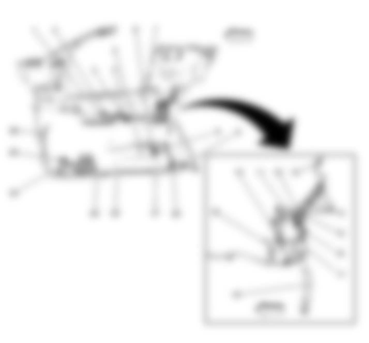
Fig. 2: Chevrolet SSR LS 2003 - Component Locations - G100, G101, G102 Component View
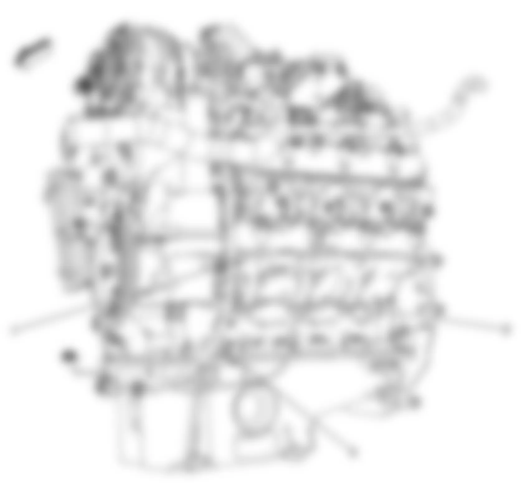
Callout Component Name 1 G101 2 G100 3 G102
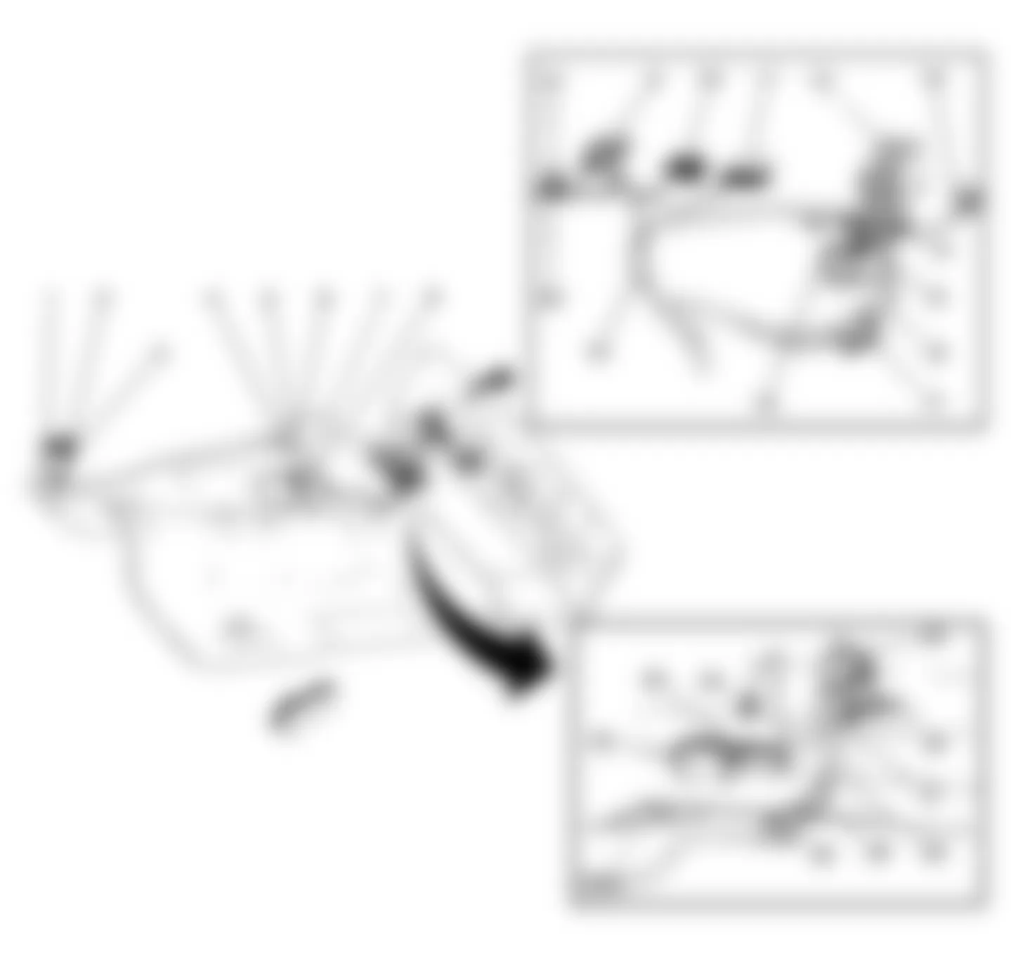
Fig. 3: Chevrolet SSR LS 2003 - Component Locations - G103 & Fuse Block - Underhood Component View
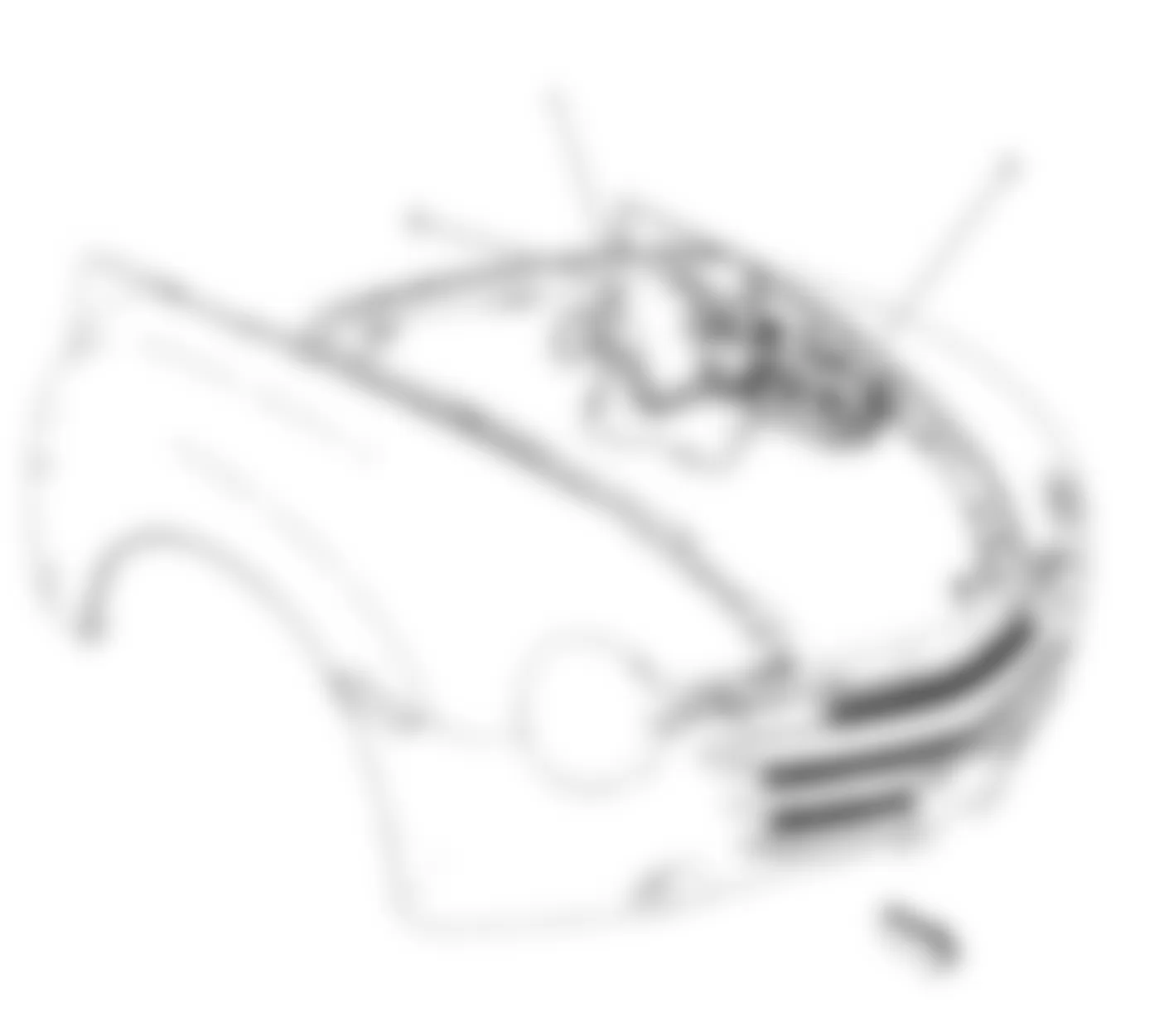
Callout Component Name 1 I/P Harness 2 Fuse Block - Underhood 3 G103
Fig. 4: Chevrolet SSR LS 2003 - Component Locations - G105 Component View
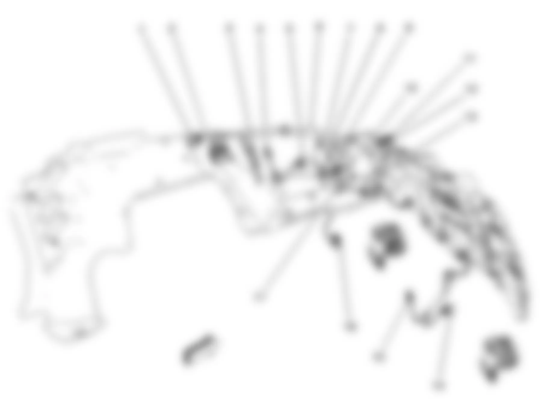
Callout Component Name 1 C103 2 Fuse Block - Underhood C4 3 Battery Feed 4 Headlamp - Low Beam Left 5 Headlamp - High Beam Left 6 S111 7 Cooling Fan 2 Relay 8 G105 9 Cooling Fan 1 Relay 10 S106 11 Cooling Fan 12 S104 13 S103 14 Headlamp - High Beam Right 15 Headlamp - Low Beam Right 16 Horn Assembly 17 S105
Fig. 5: Chevrolet SSR LS 2003 - Component Locations - G200, SP200, SP201 Component View
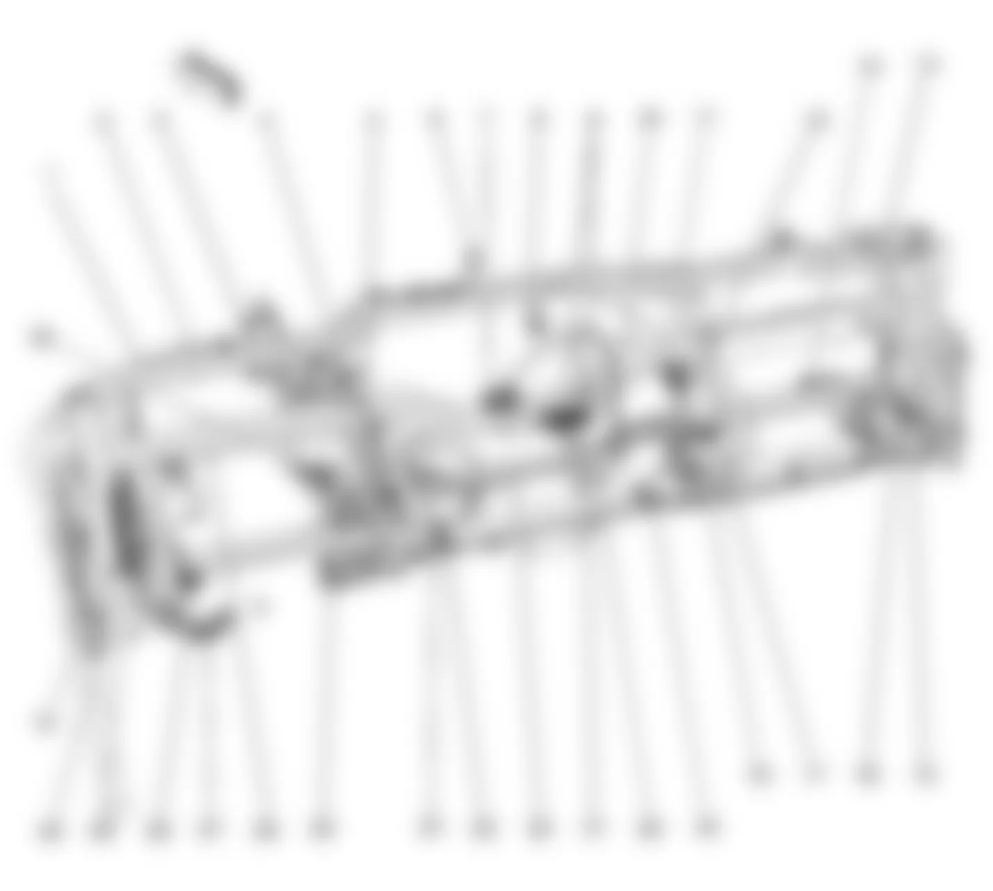
Callout Component Name 1 S205 2 S206 3 Instrument Panel Cluster Connector 4 Mode Actuator Connector 5 Noise Compensation Microphone Connector 6 Ambient Light Sensor Connector 7 Radio Connector C1 8 Air Temperature Actuator 9 HVAC Connector Module Connector C1,C2 10 Evaporator Temperature Sensor Connector 11 Inflatable Restraint I/P Module Connector 12 S209 13 Blower Motor Connector 14 Recirculation Actuator Connector 15 Inflatable Restraint I/P Module Disable Switch Connector 16 I/P Compartment Lamp Connector 17 Blower Motor Resistor Connector 18 Rear Compartment Lid Release Switch - Interior Connector 19 Auxiliary Power Outlet Front #2 Connector 20 C205 21 S208 22 S207 23 Auxiliary Power Outlet Front #1 Connector 24 Splice Pack SP200, G200 25 Turn Signal/Hazard Flasher Module Connector 26 Stop Lamp Switch Connector 27 Data Link Connector (DLC) 28 Inflatable Restraint Steering Wheel Coil Connector 29 Splice Pack SP201 30 Headlamp Switch Connector 31 C201 32 Accelerator Pedal Position (APP) Sensor Connector
Fig. 6: Chevrolet SSR LS 2003 - Component Locations - G300 Component View
Callout Component Name 1 Center Console Switch Assembly Connector 2 Automatic Transmission Shift Lock Actuator Connector 3 Auxiliary Message Center (SEO) Connector 4 Inflatable Restraint Sensing and Diagnostic Module (SDM) Connector 5 Park Brake Switch Connector 6 Fuse Block - Rear C4 Connector 7 C202 8 S300 9 Remote Control Door Lock Receiver (RCDLR) Connector 10 Body Control Module (BCM) C1, C2, C3, C4, C5 Connectors 11 C200 12 C204 13 Fuse Block - Rear C1 Connector 14 S318 15 S319 16 C300 17 Inflatable Restraint Side Impact Module - Left Connector 18 Seat Belt Pretensioner - LF Connector 19 G300 20 S202 21 S200 22 S203 23 C501 24 C500 25 I/P Harness
Fig. 7: Chevrolet SSR LS 2003 - Component Locations - G301, G302, SP300 Component View
Callout Component Name 1 C303 2 C600 3 C601 4 G301 5 Seat Belt Pretensioner - RF 6 Inflatable Restraint Side Impact Module - Right 7 C306 8 S303 9 C308 10 Roof/Door Module 11 Roof/Door Module 12 Relay Block - Rear 13 Daytime Running Lamp (DRL) Diode 14 Speaker - LR 15 Audio Amplifier C3 16 Audio Amplifier C1 17 Splice Pack SP300 18 Audio Amplifier C2 19 S307 20 Speaker - RR 21 C309 22 C202 23 C204 24 C200 25 Fuse Block - Rear C2 26 S306 27 Fuse Block - Rear C3 28 S301 29 S302 30 G302
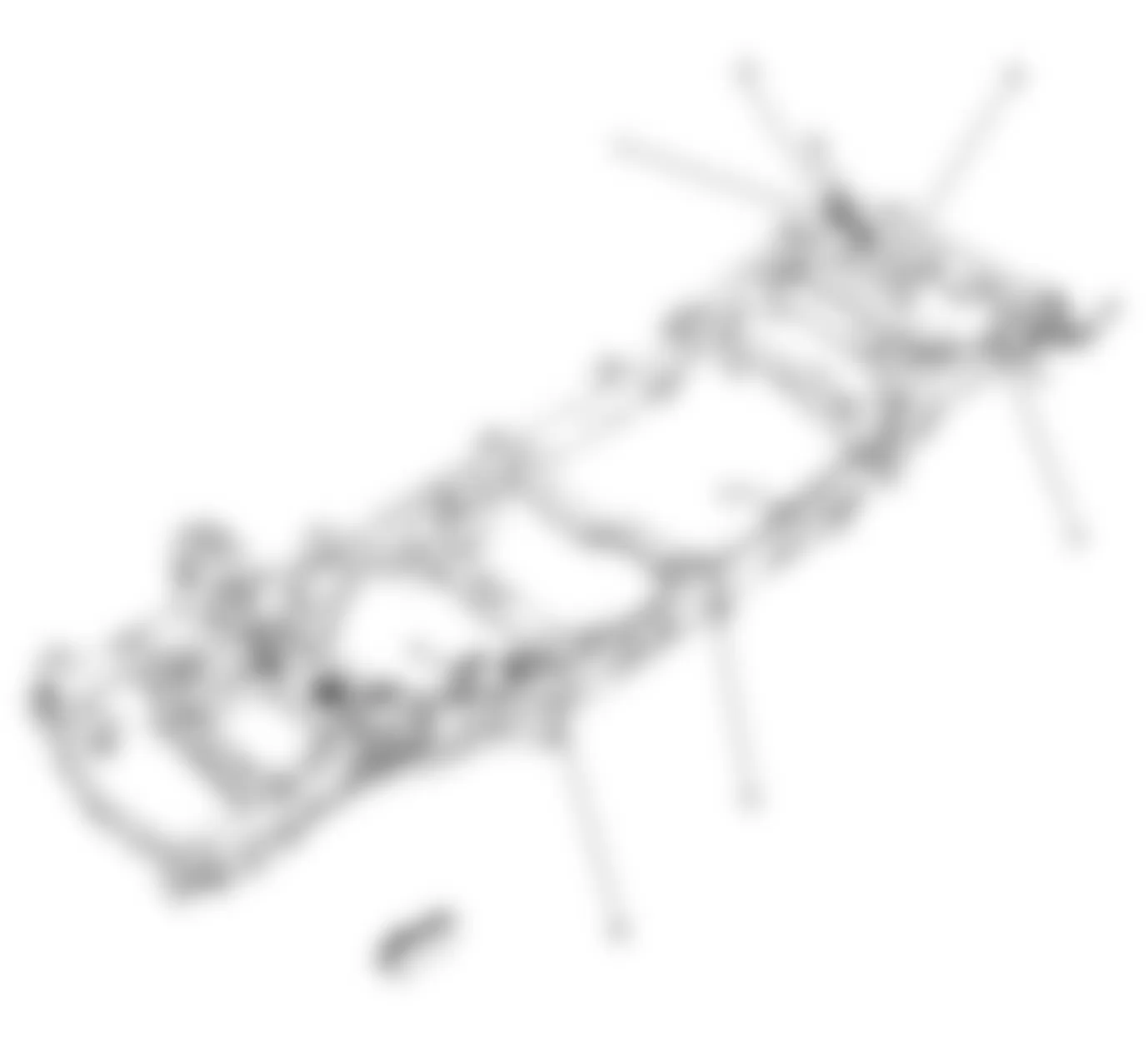
Callout Component Name 1 G405 2 G404 3 Battery 4 G402 5 G401 6 G400
Chevrolet SSR LS 2003 - Electrical Center Identification Views Fuse Block - Underhood, Label
Fig. 9: Chevrolet SSR LS 2003 - Component Locations - Fuse Block - Underhood, Label View
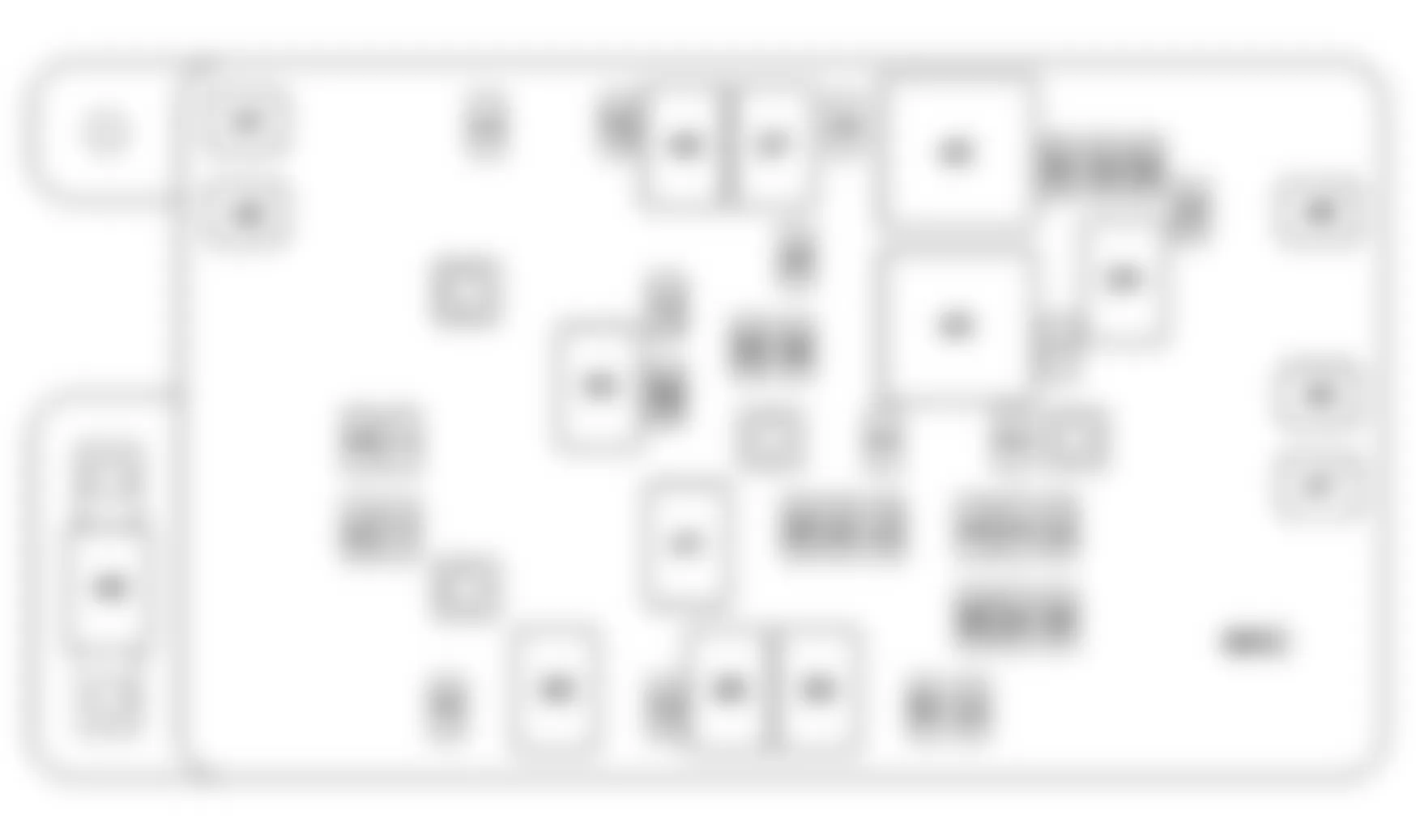
Chevrolet SSR LS 2003 Fuse Block - Underhood, Label Usage
No. Fuse Rating Description 1 A/C Fuse 10A Air Conditioning (A/C) Relay 2 BTSI Fuse 10A Stop Lamp Switch, Automatic Transmission Shift Lock Actuator 3 CANISTER Fuse 10A Evaporative Emission (EVAP) Canister Vent Solenoid 4 COILS Fuse 10A HDLP-HI Relay 5 CRNK Fuse 10A Powertrain Control Module (PCM) 6 ENG I Fuse 10A Evaporative Emissions (EVAP) Canister Purge Solenoid, Intake Air Temperature (IAT)/Mass Air Flow (MAF) Sensor 7 HI HDLP-LT Fuse 10A Left High Beam Headlamp 8 HI HDLP-RT Fuse 10A Right High Beam Headlamp 9 IGN E Fuse 10A Cooling Fan 1 Relay, Cooling Fan 2 Relay, Park/Neutral Position (PNP) Switch, Inside Rear View Mirror (DF4), Stop Lamp Switch, Instrument Panel Cluster (IPC), Turn Signal/Multifunction Switch 10 IPC/DIC Fuse 10A Instrument Panel Cluster (IPC) 11 LOW HDLP-LT Fuse 10A Left Low Beam Headlamp - Daytime Running Lamp 12 LOW HDLP-RT Fuse 10A Right Low Beam Headlamp - Daytime Running Lamp 13 PCM I Fuse 15A Powertrain Control Module (PCM) 14 SIR Fuse (Early Production) 10A Inflatable Restraint Sensing and Diagnostic Module (SDM), Inflatable Restraint I/P Module Disable Switch AIRBAG Fuse (Late Production) 10A Inflatable Restraint Sensing and Diagnostic Module (SDM), Inflatable Restraint I/P Module Disable Switch 15 TBC I Fuse 10A Body Control Module (BCM) 16 TBC IGN 1 Fuse 10A Body Control Module (BCM) 17 L-ST/TRN Fuse 10A Tail/Stop and Turn Signal Lamp - Left, Trailer Tow Feed 18 R-ST/TRN Fuse 10A Tail/Stop and Turn Signal Lamp - Right, Trailer Tow Feed 19 BCK/UP Fuse 15A Park/Neutral Position (PNP) Switch 20 ETC Fuse 15A Throttle Actuator Control (TAC) Module 21 FOG LP Fuse 15A FOG LP Relay 22 HORN Fuse 15A HORN Relay 23 INJ A Fuse 15A Left Bank Ignition Coils and Fuel Injectors 24 INJ B Fuse 15A Right Bank Ignition Coils and Fuel Injectors 25 O2A Fuse 15A HO2S1, Bank 1 and Bank 2 26 O2B Fuse 15A HO2S2, Bank 1 and Bank 2 27 W/S WASH Fuse 15A W/S WASH Relay 28 CIGAR Fuse (Early Production) 20A Data Link Connector (DLC), Cigar Lighter LTR Fuse (Late Production) 20A Data Link Connector (DLC), Cigar Lighter 29 PCM B Fuse 20A F/PMP Relay, Powertrain Control Module (PCM) 31 BED COVER RELEASE Fuse 20A BEDCOVER RELEASE Relay 32 FLASH Fuse 25A Turn Signal/Hazard Flasher Module 33 ST/LP Fuse 25A Turn Signal/Hazard Flasher Module, VEH CHMSL Fuse 44 ENG CLN FAN Fuse 60A Cooling Fan 1 Relay, Cooling Fan 2 Relay 45 BLWR Fuse 40A Blower Motor 46 IGN A Fuse 40A Starter Relay, Ignition Switch 47 IGN B Fuse 40A Ignition Switch 48 ABS Fuse 60A Electronic Brake Control Module (EBCM) 42 IGN 1 Relay - INJ A Fuse, INJ B Fuse, and Throttle Actuator Control (TAC) Fuse 43 STRTR Relay - Starter Solenoid 34 A/C Relay - A/C Compressor Clutch, Powertrain Control Module (PCM) 35 F/PMP Relay - Fuel Pump 36 FOG LP Relay - Front Fog Lamps 37 HDLP-HI Relay - Body Control Module (BCM) 38 BED COVER RELEASE Relay - Rear Compartment Lid Release Switch Exterior 39 HORN Relay - Horns 40 W/S WASH Relay - Windshield Washer Fluid Pump 41 HDM Relay - Low Beam Headlamps 49 I/P BATT Fuse 125A Fuse Block - Rear
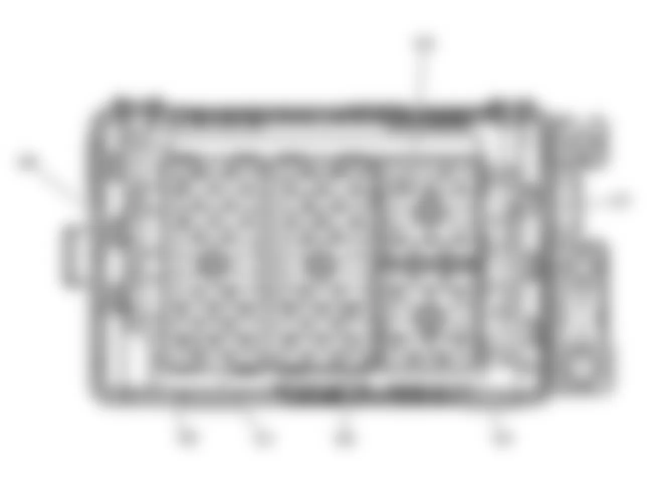
Chevrolet SSR LS 2003 - Fuse Block - Underhood, Top View
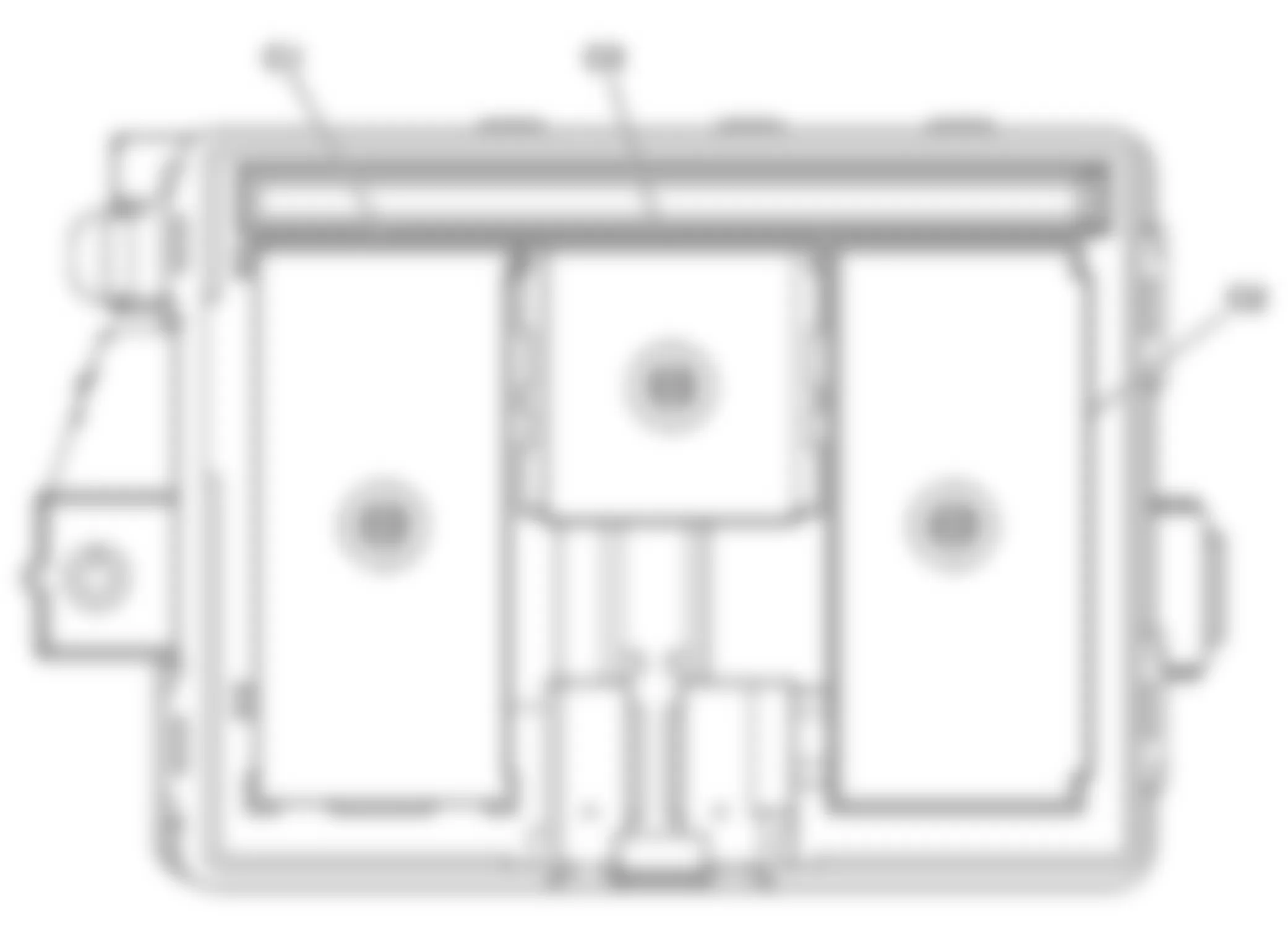
Fig. 10: Chevrolet SSR LS 2003 - Component Locations - Fuse Block - Underhood, Top View
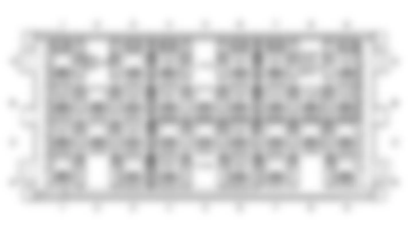
Chevrolet SSR LS 2003 - Fuse Block - Underhood, Bottom View
Fig. 11: Chevrolet SSR LS 2003 - Component Locations - Fuse Block - Underhood, Bottom View
Chevrolet SSR LS 2003 Fuse Block - Underhood C1 Connector End View
Connector Part Information
Pin Wire Color Circuit Number Function A1 - - Not Used A2 PK 1539 Run/Crank Ignition 1 Voltage PK 1539 Run/Crank Ignition 1 Voltage A3-A4 - - Not Used A5 PK 639 Run/Crank Ignition 1 Voltage A6 PU 806 Crank Voltage A7 OG/BK 463 Requested Torque Signal A8 PU 6 Starter Solenoid Crank Voltage A9 - - Not Used A10 YE 1737 Neutral Safety Switch Park/Neutral Signal A11-A12 - - Not Used B1 - - Not Used B2 PK 339 Run/Crank Ignition 1 Voltage B3-B4 - - Not Used B5 PK 239 Run/Crank Ignition 1 Voltage PK 239 Run/Crank Ignition 1 Voltage B6 - - Not Used B7 L-GN 275 Park Neutral Position Switch Park Signal B8 D-GN/WH 465 Fuel Pump Primary Relay Control B9 WH 1310 EVAP Canister Vent Solenoid Control B10 TN/BK 464 Delivered Torque Signal B11-B12 - - Not Used C1 - - Not Used C2 PK 539 Run/Crank Ignition 1 Voltage PK 539 Run/Crank Ignition 1 Voltage C3-C4 - - Not Used C5 PK 439 Run/Crank Ignition 1 Voltage C6-C9 - - Not Used C10 BK 550 Ground C11 - - Not Used C12 PK 1339 Run/Crank Ignition 1 Voltage PK 1339 Run/Crank Ignition 1 Voltage D1 - - Not Used D2 PK 1020 Off/Run/Crank Voltage D3 BK 350 Ground D4-D8 - - Not Used D9 D-GN/WH 459 A/C Compressor Clutch Relay Control D10 BK 550 Ground BK 550 Ground D11 D-GN 59 A/C Compressor Clutch Supply Voltage D12 PK 1239 Run/Crank Ignition 1 Voltage PK 1239 Run/Crank Ignition 1 Voltage E1-E5 - - Not Used E6 BK 450 Ground E7 YE/BK 625 Starter Enable Relay Control E8-E11 - - Not Used E12 PK 839 Run/Crank Ignition 1 Voltage F1-F2 - - Not Used F3 BK 350 Ground F4-F5 - - Not Used F6 BK 450 Ground BK 450 Ground F7 BK 450 Ground F8-F12 - - Not Used

Chevrolet SSR LS 2003 Fuse Block - Underhood C2 Connector End View
Connector Part Information
Pin Wire Color Circuit Number Function A1-A5 - - Not Used A6 BN 2309 Front Park Lamp Supply Voltage BN 2309 Front Park Lamp Supply Voltage A7 OG 440 Battery Positive Voltage OG 440 Battery Positive Voltage A8-A9 - - Not Used A10 YE 18 Left Rear Stop/Turn Lamp Supply Voltage A11 - - Not Used A12 OG 2268 Windshield Washer Relay Control B1 D-BU 2115 Right Turn Signal Lamp Supply Voltage B2 - - Not Used B3 PK/WH 1970 Headlamp Low Beam Relay Control B4-B5 - - Not Used B6 PK 639 Run/Crank Ignition 1 Voltage B7-B9 - - Not Used B10 PU 420 Torque Converter Clutch Brake Switch Signal PU 420 Torque Converter Clutch Brake Switch Signal B11-B12 - - Not Used C1 L-BU 2114 Left Turn Signal Lamp Supply Voltage C2 D-GN/WH 1317 Fog Lamp Relay Control C3 BN 253 Rear Compartment Lid Release Relay Signal BN 253 Rear Compartment Lid Release Relay Signal C4-C8 - - Not Used C9 OG 1540 Battery Positive Voltage C10 - - Not Used C11 BN 441 Run Ignition 3 Voltage C12 BK/WH 1969 Headlamp High Beam Relay Control D1-D4 - - Not Used D5 OG 140 Battery Positive Voltage D6-D8 - - Not Used D9 OG 640 Battery Positive Voltage OG 640 Battery Positive Voltage D10 D-GN 19 Right Rear Stop/Turn Lamp Supply Voltage D11-D12 - - Not Used E1 OG 2340 Battery Positive Voltage E2 BK 28 Horn Relay Control E3 PK 1020 Off/Run/Crank Voltage E4 - - Not Used E5 PK 39 Run/Crank Ignition 1 Voltage E6 L-GN/BK 584 Brake Transmission Shift Interlock Switch Supply Voltage L-GN/BK 584 Brake Transmission Shift Interlock Switch Supply Voltage E7-E11 - - Not Used E12 OG 1140 Battery Positive Voltage F1-F4 - - Not Used F5 YE 1139 Run/Crank Ignition 1 Voltage YE 1139 Run/Crank Ignition 1 Voltage F6 - - Not Used F7 YE 5 Crank Voltage F8-F9 - - Not Used F10 D-GN 1433 Clutch Start Switch Signal F11 RD 142 Battery Positive Voltage F12 - - Not Used

Chevrolet SSR LS 2003 Fuse Block - Underhood C3 Connector End View
Connector Part Information
Pin Wire Color Circuit Number Function A1-A6 - - Not Used B1-B4 - - Not Used B5 BN 441 Ignition 3 Voltage B6 - - Not Used C1-C5 - - Not Used C6 OG 540 Battery Positive Voltage D1 - - Not Used D2 YE 1618 Trailer Left Rear Turn/Stop Lamp Supply Voltage YE 1618 Trailer Left Rear Turn/Stop Lamp Supply Voltage D3-D4 - - Not Used D5 TN/BK 464 Delivered Torque Signal D6 - - Not Used E1-E2 - - Not Used E3 PU 420 TCC Brake Switch/Cruise Control Release Signal E4-E6 - - Not Used F1 BK 350 Ground F2 OG/BK 463 Requested Torque Signal F3 GY 120 Fuel Pump Supply Voltage F4 WH 1310 EVAP Canister Vent Solenoid Control F5 - - Not Used F6 D-GN 1619 Trailer Right Rear Turn/Stop Lamp Supply Voltage D-GN 1619 Trailer Right Rear Turn/Stop Lamp Supply Voltage

Chevrolet SSR LS 2003 Fuse Block - Underhood C4 Connector End View
Connector Part Information
Pin Wire Color Circuit Number Function A1 BN 2309 Front Park Lamps Supply Voltage BN 2309 Front Park Lamps Supply Voltage A2-A5 - - Not Used A6 L-BU 2114 Left Turn Signal Lamps Supply Voltage L-BU 2114 Left Turn Signal Lamps Supply Voltage B1 BN 2309 Front Park Lamps Supply Voltage BN 2309 Front Park Lamps Supply Voltage B2 PK 639 Ignition 1 Voltage B3-B4 - - Not Used B5 BK/WH 56 Rear Compartment Lid Release Switch Supply Voltage B6 - - Not Used C1-C4 - - Not Used C5 BK 350 Ground C6 D-BU 2115 Right Turn Signal Lamps Supply Voltage D-BU 2115 Right Turn Signal Lamps Supply Voltage D1-D6 - - Not Used E1 D-GN/WH 711 Left Headlamp High Beam Supply Voltage E2 PU 359 DRL Supply Voltage/DRL Off Indicator Control E2 YE 712 Left Headlamp Low Beam Supply Voltage E3 - - Not Used E4 RD 228 Windshield Washer Pump Control E5-E6 - - Not Used F1 L-GN/BK 311 Right Headlamp High Beam Supply Voltage F2 TN/WH 312 Right Headlamp Low Beam Supply Voltage F2 PU 359 DRL Supply Voltage/DRL Off Indicator Control F3 - - Not Used F4 D-GN 1329 Horn Fuse Supply Voltage F5 - - Not Used F6 PU 34 Roof Off-Road Lamps Supply Voltage 2 PU 34 Roof Off-Road Lamps Supply Voltage 2

Chevrolet SSR LS 2003 Fuse Block - Underhood C5 Connector End View
Connector Part Information
Pin Wire Color Circuit Number Function A RD 342 Battery Positive Voltage B PK 3 Run/Crank Ignition 1 Voltage

Chevrolet SSR LS 2003 Fuse Block - Underhood C6 Connector End View
Connector Part Information
Pin Wire Color Circuit Number Function A - - Not Used B RD 542 Battery Positive Voltage

Chevrolet SSR LS 2003 Fuse Block - Underhood C7 Connector End View
Connector Part Information
Pin Wire Color Circuit Number Function A - - Ground B RD 642 Battery Positive Voltage

Chevrolet SSR LS 2003 - Fuse Block - Rear, Label
Fig. 12: Chevrolet SSR LS 2003 - Component Locations - Fuse Block - Rear, Label View
Chevrolet SSR LS 2003 Fuse Block - Rear, Label Usage
No. Fuse Rating Description 1 Roof-Door MOD Circuit Breaker 30A Roof Door Module 2 ROOF PUMP Circuit Breaker 30A Retractable Roof Motor Left Relay, Retractable Roof Motor Right Relay 3 R/DEFG Fuse 30A Defrost Relay, Rear Defogger Relay 4 TBC 3 Fuse 15A Body Control Module 5 DEFG CONT Fuse 10A Outside Rear View Mirror - Driver, Outside Rear View Mirror - Passenger, Rear Defogger Relay 6 DR SEAT MOD Fuse 10A Memory Seat Module - Driver 7 TBC 2 Fuse 15A Body Control Module 8 SEATS Circuit Breaker 30A Seats 9 - - Not Used 10 DDM Fuse 10A Outside Rear View Mirror Switch, Driver Door Unlock Relay 11 AMP Fuse 25A Audio Amplifier 12 - - Not Used 13 DRL Fuse 15A DRL Relays 14 LR PRK Fuse 10A Left Rear Park Lamps 15 AUX PWR 2 Fuse 20A Auxiliary Power Outlet - Rear 16 VEH CHMSL Fuse 10A Center High Mounted Stop Lamp 17 RR PRK Fuse 10A Right Rear Park Lamps 18 LOCK Relay - Power Door Lock 19-20 - - Not Used 21 LOCKS Fuse 15A Lock and Unlock Relays 22- 23 - - Not Used 24 UNLOCK Relay - Power Door Unlocks 25-26 - - Not Used 27 UGDO 10A Inside Rear View Mirror 28 RDM 2 Fuse 15A Roof Door Module 29 - - Not Used 30 PRK LP Relay - Park Lamps 31 TBC 4CC Fuse 10A Body Control Module 32 RKE Fuse 10A Remote Control Door Lock Receiver 33 FT WPR Fuse 25A Windshield Wiper Motor 34 STOP Fuse 15A Stop Lamps 35 - - Not Used 36 HVAC B DD Unlock Fuse 10A HVAC Control Module 37 F/PRK Fuse 10A Front Park Lamps 38 L/TURN Fuse 10A Left Turn Lamps 39 HVAC I Fuse 10A HVAC Control Module, Turn Signal Multifunction Switch, Air Temperature Sensor, Center Switch Console 40 TBC 4 Fuse 10A Body Control Module 41 RDO Fuse 15A Radio 42 TR PRK FUSE 10A Trailer Tow Park Lamps Feed 43 R/TURN Fuse 10A Right Turn Lamps 44 - - Not Used 45 DEFROST Relay - Rear Defogger, Outside Rear View Mirrors 46 AUX PWR Fuse 20A Auxiliary Power Outlets 47 IGN 0 Fuse 10A Retractable Roof, Powertrain Control Module, Automatic Transmission 48-49 - - Not Used 50 TBC IG Fuse 10A Body Control Module 51 BRK Fuse 10A Electronic Brake Control Module 52 - - Not Used
Chevrolet SSR LS 2003 - Fuse Block - Rear, Top View
Fig. 13: Chevrolet SSR LS 2003 - Component Locations - Fuse Block - Rear, Top View
Chevrolet SSR LS 2003 - Fuse Block - Rear, Bottom View
Fig. 14: Chevrolet SSR LS 2003 - Component Locations - Fuse Block - Rear, Bottom View
Chevrolet SSR LS 2003 Fuse Block - Rear C1 Connector End View
Connector Part Information
Pin Wire Color Circuit Number Function A1 - - Not Used A2 BN/WH 230 Instrument Panel Lamp Dimming Control A3 - - Not Used A4 L-GN 24 Backup Lamp Supply Voltage L-GN 24 Backup Lamp Supply Voltage A5 L-GN 1391 Left Front Door Lock Relay Control A6 BN 4 Accessory Voltage A7 YE 143 Accessory Voltage A8 BN 341 Run Ignition 3 Voltage BN 341 Run Ignition 3 Voltage A9 PK 1020 Off/Run/Crank Voltage A10-A11 - - Not Used A12 OG 1732 Electronic Control Unit 12-Volt Reference (3) OG 1732 Electronic Control Unit 12-Volt Reference (3) B1-B3 - - Not Used B4 WH 17 Stop Lamp Switch Signal B5 L-BU 1320 CHMSL Supply Voltage B6-B7 - - Not Used B8 BN 341 Run Ignition 3 Voltage BN 341 Run Ignition 3 Voltage B9-B12 - - Not Used C1 OG 4340 Battery Positive Voltage C2 - - Not Used C3 BN 2309 Front Park Lamp Supply Voltage C4 L-BU 2114 Left Turn Signal Lamp Supply Voltage L-BU 2114 Left Turn Signal Lamp Supply Voltage C5 YE 685 Air Inlet Valve Solenoid Control C6-C7 - - Not Available C8 BN 341 Run Ignition 3 Voltage BN 341 Run Ignition 3 Voltage C9-C12 - - Not Used D1 OG 340 Battery Positive Voltage D2 - - Not Used D3 BN 2109 Trailer Park Lamp Supply Voltage D4 D-BU 2115 Right Turn Signal Lamp Supply Voltage D-BU 2115 Right Turn Signal Lamp Supply Voltage D5 TN 686 Air Inlet Valve Solenoid Control D6-D8 - - Not Available D9 OG 300 Run Ignition 3 Voltage D10 TN 294 Door Lock Actuator Unlock Control D11-D12 - - Not Used E1-E5 - - Not Used E6 WH 1390 Off/Run/Crank Voltage E7 PK 1020 Off/Run/Crank Voltage E8-E9 - - Not Used E10 D-BU/WH 2218 Rear Recirculation/A/C Request Signal E11 - - Not Used E12 PK 639 Run/Crank Ignition 1 Voltage F1 - - Not Used F2 L-BU 292 Rear Defog Switch Signal F3 OG 1040 Battery Positive Voltage OG 1040 Battery Positive Voltage F4 PK 1020 Off/Run/Crank Voltage F5-F7 - - Not Used F8 BN 441 Run Ignition 3 Voltage F9-F12 - - Not Used
Chevrolet SSR LS 2003 Fuse Block - Rear C2 Connector End View
Connector Part Information
Pin Wire Color Circuit Number Function A1 OG 3640 Battery Positive Voltage A2 - - Not Used A3 OG 1340 Battery Positive Voltage A4-A5 - - Not Used A6 OG 2740 Battery Positive Voltage A7 - - Not Used A8 OG 1240 Battery Positive Voltage A9 PU 359 DRL Supply Voltage/DRL Off Indicator Control A10-A11 - - Not Used A12 BK/WH 746 Right Front Door Ajar Switch Signal BK/WH 746 Right Front Door Ajar Switch Signal B1 OG 267 Heated Mirror/Rear Defog Relay Coil Supply Voltage OG 267 Heated Mirror/Rear Defog Relay Coil Supply Voltage B2-B12 - - Not Used C1 OG 3540 Battery Positive Voltage C2-C9 - - Not Used C10 OG 4140 Battery Positive Voltage OG 4140 Battery Positive Voltage C11-C12 - - Not Used D1 OG 2240 Battery Positive Voltage (Base) OG 3540 Battery Positive Voltage (Uplevel) D2 BN 2509 Left Rear Park Lamps Supply Voltage BN 2509 Left Rear Park Lamps Supply Voltage D3-D4 - - Not Used D5 OG 3740 Battery Positive Voltage (Uplevel) D6-D7 - - Not Used D8 TN 294 Door Lock Actuator Unlock Control D9-D11 - - Not Used D12 BK 1576 Rear Compartment Lid Release Switch Signal E1 OG 840 Battery Positive Voltage E2 BN 2509 Left Rear Park Lamps Supply Voltage E3-E5 - - Not Used E6 L-GN 1391 Driver Door Unlock Relay Control E7-E8 - - Not Used E9 L-GN/BK 592 DRL Relay Control/DRL Low Control E10 OG 2040 Battery Positive Voltage E11 - - Not Used E12 BN 253 Rear Compartment Lid Release Relay Signal F1 YE 820 CHMSL Supply Voltage F2 BN/WH 2609 Right Rear Park Lamps Supply Voltage/Park Lamps Supply Voltage BN/WH 2609 Right Rear Park Lamps Supply Voltage/Park Lamps Supply Voltage F3-F5 - - Not Used F6 GY 295 Door Lock Actuator Lock Control GY 295 Door Lock Actuator Lock Control F7 - - Not Used F8 BK 1450 Ground F9 - - Not Used F10 GY 1698 Antenna Select Supply Voltage F11 - - Not Used F12 PU 359 DRL Supply Voltage/DRL Off Indicator Control

Chevrolet SSR LS 2003 Fuse Block - Rear C3 Connector End View
Connector Part Information
Pin Wire Color Circuit Number Function A1-A6 - - Not Used B1-B5 - - Not Used B6 GY/BK 690 Courtesy Lamp Low Control C1-C6 - - Not Used D1-D5 - - Not Used D6 L-GN 24 Backup Lamp Supply Voltage E1 OG 3140 Battery Positive Voltage E2 PK 639 Ignition 1 Voltage E3 - - Not Used E4 OG 1840 Battery Positive Voltage E5 - - Not Used E6 D-BU/WH 2218 Class 2 Serial Data F1-F2 - - Not Used F3 PK 1020 Ignition 0 Voltage F4 TN 294 Door Lock Actuator Unlock Control F5 - - Not Used F6 OG 1732 Inadvertent Power Supply Voltage/Inadvertent Power Courtesy Lamp
Chevrolet SSR LS 2003 Fuse Block - Rear C4 Connector End View
Connector Part Information
Pin Wire Color Circuit Number Function A1 OG 2140 Battery Positive Voltage A2 - - Not Used A3 BK/WH 746 Right Front Door Ajar Switch Signal A4 - - Not Used A5 GY/BK 255 Door Lock Relay Control A6-A7 - - Not Used A8 GY 1698 Antenna Select Power Signal A9-A12 - - Not Used A13 TN/BK 254 Door Unlock Relay Control A14 WH 1080 Park Lamp Relay Control A15-A17 - - Not Used A18 PK 1390 Off/Run/Crank Voltage A19-A20 - - Not Used B1 BN/WH 230 Instrument Panel Lamp Dimming Control B2 BN/WH 230 Instrument Panel Lamp Dimming Control B3 GY/BK 690 Courtesy Lamp Relay Control B4 OG 2240 Battery Positive Voltage B5 BN 253 Rear Compartment Lid Release Relay Signal B6 BK 1576 Rear Compartment Lid Release Switch Signal B7 PU 359 DRL Supply Voltage B8 PU 359 DRL Supply Voltage B9 L-GN/BK 592 DRL Relay Control B10-B11 - - Not Used B12 L-GN 24 Backup Lamp Supply Voltage B13 OG 4440 Battery Positive Voltage B14 - - Not Used B15 YE 343 Accessory Voltage B16 - - Not Used B17 OG 4040 Battery Positive Voltage B18 OG 1732 Electronic Control Unit 12-Volt Reference (3) B19-B20 - - Not Used

Chevrolet SSR LS 2003 - Relay Block - Rear, Label
Fig. 15: Chevrolet SSR LS 2003 - Component Locations - Relay Block - Rear, Label View

Chevrolet SSR LS 2003 Relay Block - Rear, Label Usage
Fuse Rating Description Driver Door Unlock Relay - Driver Door Unlock Control RT DRL - Right Daytime Running Lamp (DRL) Control LT DRL - Left Daytime Running Lamp (DRL) Control Rear Defogger Relay - Rear Window Defogger Grid
Chevrolet SSR LS 2003 - Relay Block - Rear, Top View
Fig. 16: Chevrolet SSR LS 2003 - Component Locations - Relay Block - Rear, Top View
Chevrolet SSR LS 2003 Relay Block - Rear Connector End View
Connector Part Information
Pin Wire Color Circuit Number Function A1-A3 - - Not Used A4 YE 634 DRL Diode Supply Voltage YE 634 DRL Diode Supply Voltage A5 - - Not Used A6 OG 840 Battery Positive Voltage OG 840 Battery Positive Voltage A7 TN 294 Door Lock Actuator Unlock Control A8 - - Not Used A9 L-GN 1391 Driver Door Unlock Relay Control B1 OG 3640 Battery Positive Voltage B2 - - Not Used B3 BK 1450 Ground BK 1450 Ground B4 L-GN/BK 592 DRL Relay Control/DRL Low Control L-GN/BK 592 DRL Relay Control/DRL Low Control B5 - - Not Used B6 PU 359 DRL Supply Voltage/DRL Off Indicator Control B7 OG 4140 Battery Positive Voltage B8 BK 1450 Ground B9 OG 4140 Battery Positive Voltage OG 4140 Battery Positive Voltage C1 OG 267 Heated Mirror/Rear Defog Relay Coil Supply Voltage C2 - - Not Used C3 OG 293 Rear Defog Element Supply Voltage C4 YE 634 DRL Diode Supply Voltage C5 - - Not Used C6 OG 840 Battery Positive Voltage C7-C9 - - Not Used D1-D3 - - Not Used D4 L-GN/BK 592 DRL Relay Control/DRL Low Control D5 - - Not Used D6 PU 359 DRL Supply Voltage/DRL Off Indicator Control D7-D9 - - Not Used
