Chrysler Concorde 1993 - 1993 ENGINE PERFORMANCE Tests W/Codes - 3.3L (VIN T) & 3.5L
Chrysler Concorde 1993 - INTRODUCTION SYSTEM DIAGNOSTICS
The self-diagnostic capabilities of this system, if properly utilized, can simplify testing. The Powertrain Control Module (PCM) monitors several different engine control system circuits.
If a problem is sensed with a monitored circuit, PCM memory stores a fault, the CHECK ENGINE light glows and PCM enters limp-in mode. In limp-in mode, PCM compensates for component failure by substituting information from other sources. This allows vehicle operation until repairs can be made.
Test circuits and repair or replace components as required. If problem is repaired or ceases to exist, the PCM cancels fault after 50 ignition on/off cycles.
A specific fault results from a particular system failure. A fault does not condemn a specific component; component is not necessarily the reason for failure. Faults only call out a probable malfunction area.
Chrysler Concorde 1993 - Hard Failures
Hard failures cause CHECK ENGINE light to glow and remain on until the malfunction is repaired. If light comes on and remains on (light may flash) during vehicle operation, cause of malfunction must be determined using self-diagnostic tests. If a sensor fails, PCM will use a substitute value in its calculations, allowing engine to operate in limp-in mode. In this condition, vehicle will run, but driveability may be poor.
Chrysler Concorde 1993 - Intermittent Failures
Intermittent failures may cause CHECK ENGINE light to flicker or stay on until the intermittent fault goes away. However, the corresponding fault will be retained in PCM memory. If related fault does not reoccur within a certain time frame, related fault will be erased from PCM memory. Intermittent failures can be caused by a faulty sensor, bad connector or wiring related problems.
Chrysler Concorde 1993 - MODEL IDENTIFICATION
Chrysler Concorde 1993 VEHICLE BODY IDENTIFICATION
Model Name Body Type Concorde, Intrepid & Vision LH
Chrysler Concorde 1993 - SELF-DIAGNOSTIC SYSTEM SERVICE PRECAUTIONS
Before proceeding with diagnosis, the following precautions must be followed:
- ALWAYS relieve fuel pressure before disconnecting any fuel injection-related component. DO NOT allow fuel to contact engine or electrical components. See FUEL PRESSURE RELEASE .
- When battery is disconnected, vehicle computer and memory systems may lose memory data. Driveability problems may exist until computer systems have completed a relearn cycle. See COMPUTER RELEARN PROCEDURES article in GENERAL INFORMATION before disconnecting battery.
- Vehicle must have a fully charged battery and functional charging system.
- Probe PCM 60-pin connector from pin side. DO NOT backprobe PCM connector.
- DO NOT cause short circuits when performing electrical tests. This will set additional faults, making diagnosis of original problem more difficult.
- DO NOT use a test light instead of a voltmeter.
- When checking for spark, ensure coil wire is NO more than 1/4" from ground. If coil wire is more than 1/4" from ground, damage to vehicle electronics and/or PCM may result.
- DO NOT prolong testing of fuel injectors or engine may hydrostatically (liquid) lock.
- Always repair lowest fault code number (CHECK ENGINE light) or first fault displayed (DRB-II) first.
- Always perform verification procedure test after repairs are made.
- Always disconnect DRB-II after use.
- Always disconnect DRB-II before charging battery.
Chrysler Concorde 1993 - VISUAL INSPECTION
Most driveability problems in the engine control system result from faulty wiring, poor electrical connections or leaking air and vacuum hose connections. To avoid unnecessary component testing, perform a visual inspection before beginning self-diagnostic tests.
Chrysler Concorde 1993 - DIAGNOSTIC PROCEDURE
NOTE: DO NOT skip any steps in self-diagnostic tests or incorrect diagnosis may result. Ensure self-diagnostic tests apply to engine being tested.
If no faults were found while performing BASIC DIAGNOSTIC PROCEDURES, proceed with self-diagnostics. Always perform a visual inspection before attempting to diagnose engine control system problems. See VISUAL INSPECTION . Enter on-board diagnostics, and retrieve fault code(s) using CHECK ENGINE light or retrieve fault messages using DRB-II. See ENTERING ON-BOARD DIAGNOSTICS . If faults are not present and/or DRB-II (Diagnostic Readout Box-II) is used, proceed to TEST FC-1A. Perform indicated VERIFICATION PROCEDURE test after repairs.
Chrysler Concorde 1993 - ENTERING ON-BOARD DIAGNOSTICS
NOTE: Although other scan testers are available, manufacturer recommends using DRB-II (Diagnostic Readout Box II) to diagnose the system. CHECK ENGINE light function can be used but has limited diagnostic capability.
Chrysler Concorde 1993 - CHECK ENGINE Light Diagnostic Mode
- Start engine (if possible). Move transmission shift lever through all positions, ending in Park. Turn A/C switch on and then off (if equipped).
- Turn engine off. Without starting engine again, turn ignition on, off, on, off and on within 5 seconds. Record 2-digit fault codes as displayed by flashing CHECK ENGINE light.
- For example, fault code 23 is displayed as flash, flash, 4-second pause, flash, flash, flash. After a slightly longer pause, other codes stored are displayed in numerical order.
- When CHECK ENGINE light begins to flash fault codes, it cannot be stopped. Start over if count is lost. Code 55 indicates end of fault code display.
- - FAULT CODES/MESSAGE table to translate trouble code number to a DRB-II fault message. Once trouble area is identified, re-fer to TEST FC-1A. Use DRB-II fault messages to find appropriate test.
- As an example, a 3.0L engine starts and runs but has a driveability problem. CHECK ENGINE light indicates a Code 14. - FAULT CODES/MESSAGES to translate trouble code number to a DRB-II fault message.
- When DRB-II fault message is obtained, refer to appropriate test number. To clear fault codes, see CLEARING FAULTS .
Chrysler Concorde 1993 - DRB-II Diagnostic Mode
- Turn ignition off. Connect DRB-II to engine diagnostic connector. Engine diagnostic connector is located in engine compartment, near PCM.
- Start engine (if possible). With foot on brake, move transmission shift lever through all positions, ending in PARK. Turn A/C switch on and then off (if equipped).
- Turn engine off. Without starting engine again, turn ignition on. Enter FUEL/IGN FAULTS menu. Press "2" key selecting READ FAULTS. DRB-II will display fault messages.
- When DRB-II fault message is obtained, refer to appropriate test number. To clear fault codes, see CLEARING FAULTS .
Chrysler Concorde 1993 - CLEARING FAULTS
CAUTION: When battery is disconnected, vehicle computer and memory systems may lose memory data. Driveability problems may exist until computer systems have completed a relearn cycle. See COMPUTER RELEARN PROCEDURES article in GENERAL INFORMATION before disconnecting battery.
- If DRB-II is not available, go to step 3). If DRB-II is available, press "1" key selecting FUEL/IGNITION. Press "2" key selecting READ FAULTS. Press down arrow key selecting next screen. Press "2" key selecting ERASE.
- DRB-II will display ERASE FAULTS ARE YOU SURE? (ENTER TO ERASE). Press ENTER key. When DRB-II is finished erasing faults, screen will display FAULTS ERASED.
- Fault codes may be cleared by disconnecting negative battery cable for at least 15 seconds, allowing PCM to clear faults.
Chrysler Concorde 1993 - INACTIVE FAULT CONDITION
This procedure applies if you have been sent here from diagnostic charts and have just attempted to simulate the condition that initially set the fault message. The following additional checks may assist in identifying a possible intermittent problem:
- Visually inspect related wiring harness connectors for broken, bent, pushed out or corroded terminals.
- Visually inspect related wiring harnesses for chafed, pierced or partially broken wires.
- Check all pertinent TECH SERVICE BULLETINS (TSBs).
Chrysler Concorde 1993 - USING DRB-II
NOTE: Although other scan testers are available, manufacturer recommends using DRB-II (Diagnostic Readout Box II) to diagnose the system.
Ensure DRB-II is connected to engine diagnostic connector located in engine compartment. Ensure correct cartridge is installed in DRB-II for vehicle and system being diagnosed. Menu selections will vary depending on vehicle and system being diagnosed. Follow DRB-II screen prompts to actuate, adjust, monitor, reset, test and diagnose system as necessary.
DRB-II is grounded through engine diagnostic connector, only one volt-ohmmeter test lead is required when using volt-ohmmeter option. DRB-II volt-ohmmeter should only be used when self-diagnostic tests require the use of this option.
If DRB-II has a blank screen or displays RAM TEST FAILURE, CARTRIDGE ERROR, KEY PAD TEST FAILURE or LOW OR HIGH BATTERY, this indicates a DRB-II failure. To diagnose and correct these conditions, see TESTS W/CODES - 3.3L/3.5L article in the ENGINE PERFORMANCE Section.
Chrysler Concorde 1993 - FUEL PRESSURE RELEASE
CAUTION: When battery is disconnected, vehicle computer and memory systems may lose memory data. Driveability problems may exist until computer systems have completed a relearn cycle. See COMPUTER RELEARN PROCEDURES article in GENERAL INFORMATION before disconnecting battery.
Chrysler Concorde 1993 - Multi-Point Injection (MPI)
- Turn ignition off. Disconnect negative battery cable. Slowly open fuel tank cap to release pressure in tank. Remove fuel rail pressure test port cap. Place open end of Fuel Pressure Release Hose (C-4799-A) in approved gasoline container.
- Connect other end of pressure release hose to test port. As fuel pressure release hose is tightened onto fuel rail pressure test port, fuel pressure will bleed-off into container.
CAUTION: DO NOT energize only one injector to relieve fuel pressure. Energize 3 different injectors. Energizing only one injector to relieve all fuel pressure may hydrostatically lock engine. DO NOT ground injector for more than 5 seconds.
Chrysler Concorde 1993 - DTC & FAULT CODES/MESSAGES
NOTE: DRB-II display may vary depending on vehicle application. Not all fault codes apply to all vehicles. Some fault codes have more than one meaning. When a fault code has more than one meaning, CHECK ENGINE light is unable to distinguish between different failures.
Chrysler Concorde 1993 - FAULT CODES/MESSAGES
NOTE: For DTC table, see TEST FC-1A under FAULT CODE TESTS.
Chrysler Concorde 1993 - Code 11
DRB-II displays NO CRANK REFERENCE SIGNAL AT PCM. Condition is: no distributor or camshaft reference signal picked up during cranking.
Chrysler Concorde 1993 - Code 13
DRB-II displays SLOW CHANGE IN IDLE MAP SENSOR SIGNAL. Condition is: Manifold Absolute Pressure (MAP) sensor output change slower and/or smaller than expected.
Chrysler Concorde 1993 - Code 13
DRB-II displays NO CHANGE IN MAP FROM START TO RUN. Condition is: no difference recognized between Manifold Absolute Pressure (MAP) reading and barometric (atmospheric) pressure reading at start-up.
Chrysler Concorde 1993 - Code 14
DRB-II displays MAP VOLTAGE TOO LOW. Condition is: Manifold Absolute Pressure (MAP) sensor input less than minimum acceptable voltage.
Chrysler Concorde 1993 - Code 14
DRB-II displays MAP VOLTAGE TOO HIGH. Condition is: Manifold Absolute Pressure (MAP) sensor input more than maximum acceptable voltage.
Chrysler Concorde 1993 - Code 15
DRB-II displays NO VEHICLE SPEED SENSOR SIGNAL. Condition is: no Vehicle Speed Sensor (VSS) signal detected with road load conditions.
Chrysler Concorde 1993 - Code 16
DRB-II displays KNOCK SENSOR #1 CIRCUIT or KNOCK SENSOR #2 CIRCUIT. Condition is: open or shorted condition detected in knock sensor circuit.
Chrysler Concorde 1993 - Code 17
DRB-II displays ENGINE IS COLD TOO LONG. Condition is: coolant temperature stays less than normal operating temperature during vehicle operation.
Chrysler Concorde 1993 - Code 21
DRB-II displays O2S STAYS AT CENTER. Condition is: no rich or lean signal detected from oxygen sensor input.
Chrysler Concorde 1993 - Code 21
DRB-II displays O2S SHORTED TO VOLTAGE. Condition is: oxygen sensor input voltage maintained at more than normal operating range.
Chrysler Concorde 1993 - Code 22
DRB-II displays ECT SENSOR VOLTAGE TOO LOW. Condition is: Engine Coolant Temperature (ECT) sensor input less than minimum acceptable voltage.
Chrysler Concorde 1993 - Code 22
DRB-II displays ECT SENSOR VOLTAGE TOO HIGH. Condition is: Engine Coolant Temperature (ECT) sensor input more than maximum acceptable voltage.
Chrysler Concorde 1993 - Code 23
DRB-II displays INTAKE AIR TEMPERATURE SENSOR VOLTAGE LOW. Condition is: Intake Air Temperature (IAT) sensor input less than minimum acceptable voltage.
Chrysler Concorde 1993 - Code 23
DRB-II displays INTAKE AIR TEMPERATURE SENSOR VOLTAGE HIGH. Condition is: Intake Air Temperature (IAT) sensor input more than maximum acceptable voltage.
Chrysler Concorde 1993 - Code 24
DRB-II displays THROTTLE POSITION SENSOR VOLTAGE LOW. Condition is: Throttle Position Sensor (TPS) input less than minimum acceptable voltage.
Chrysler Concorde 1993 - Code 24
DRB-II displays THROTTLE POSITION SENSOR VOLTAGE HIGH. Condition is: Throttle Position Sensor (TPS) input more than maximum acceptable voltage.
Chrysler Concorde 1993 - Code 25
DRB-II displays IDLE AIR CONTROL MOTOR CIRCUITS. Condition is: open or shorted condition detected in one or more Idle Air Control (IAC) motor circuits.
Chrysler Concorde 1993 - Code 27
DRB-II displays INJECTOR #1-6 CONTROL CIRCUIT. Condition is: injector output driver does not respond properly to Powertrain Control Module (PCM) control signal.
Chrysler Concorde 1993 - Code 31
DRB-II displays EVAP PURGE SOLENOID CKT. Condition is: open or shorted condition detected in purge solenoid circuit.
Chrysler Concorde 1993 - Code 32
DRB-II displays EGR SOLENOID CIRCUIT. Condition is: open or shorted condition detected in Exhaust Gas Recirculation (EGR) transducer solenoid circuit.
Chrysler Concorde 1993 - Code 32
DRB-II displays EGR SYSTEM FAILURE. Condition is: Powertrain Control Module (PCM) did not detect required air/fuel change during diagnostic test.
Chrysler Concorde 1993 - Code 33
DRB-II displays A/C CLUTCH RELAY CIRCUIT. Condition is: open or shorted condition detected in A/C clutch relay circuit.
Chrysler Concorde 1993 - Code 33
DRB-II displays A/C PRESSURE SENSOR HIGH. Condition is: open condition detected in A/C pressure sensor circuit.
Chrysler Concorde 1993 - Code 33
DRB-II displays A/C PRESSURE SENSOR LOW. Condition is: shorted condition detected in A/C pressure sensor circuit.
Chrysler Concorde 1993 - Code 34
DRB-II displays SPEED CONTROL SOLENOID CIRCUITS. Condition is: open or shorted condition detected in Speed Control (S/C) vacuum or vent solenoid circuits.
Chrysler Concorde 1993 - Code 35
DRB-II displays RADIATOR FAN RELAY CIRCUIT. Condition is: open or shorted condition detected in radiator fan relay circuit.
Chrysler Concorde 1993 - Code 35
DRB-II displays LOW SPEED FAN CTRL RELAY CIRCUIT. Condition is: open or shorted condition detected in low speed radiator fan relay circuit.
Chrysler Concorde 1993 - Code 35
DRB-II displays HIGH SPEED FAN RELAY CIRCUIT. Condition is: open or shorted condition detected in high speed radiator fan relay circuit.
Chrysler Concorde 1993 - Code 36
DRB-II displays TC WASTEGATE SOLENOID CIRCUIT. Condition is: open or shorted condition detected in turbocharger wastegate control solenoid circuit.
Chrysler Concorde 1993 - Code 37
DRB-II displays TORQUE CONVERTER CLUTCH SOLENOID CIRCUIT. Condition is: open or shorted condition detected in Torque Converter Clutch (TCC) solenoid circuit.
Chrysler Concorde 1993 - Code 41
DRB-II displays GENERATOR FIELD NOT SWITCHING PROPERLY. Condition is: open or shorted condition detected in alternator field circuit.
Chrysler Concorde 1993 - Code 42
DRB-II displays AUTO SHUTDOWN RELAY CONTROL CIRCUIT. Condition is: open or shorted condition detected in Auto Shutdown (ASD) relay circuit.
Chrysler Concorde 1993 - Code 43
DRB-II displays IGNITION COIL #1-3 CONTROL CIRCUIT. Condition is: open or shorted condition detected in ignition coil driver circuit.
Chrysler Concorde 1993 - Code 44
DRB-II displays BATTERY TEMP SENSOR VOLTS OUT OF LIMIT. Condition is: Powertrain Control Module (PCM) failure.
Chrysler Concorde 1993 - Code 45
DRB-II displays TURBO BOOST LIMIT EXCEEDED. Condition is: turbo boost has exceeded a preset value stored in Powertrain Control Module (PCM).
Chrysler Concorde 1993 - Code 46
DRB-II displays CHARGING SYSTEM VOLTAGE TOO HIGH. Condition is: battery voltage sense input more than target charging voltage during engine operation.
Chrysler Concorde 1993 - Code 47
DRB-II displays CHARGING SYSTEM VOLTAGE TOO LOW. Condition is: battery voltage sense input less than target charging voltage during engine operation.
Chrysler Concorde 1993 - Code 51
DRB-II displays O2S STAYS BELOW CENTER (LEAN). Condition is: oxygen sensor input indicates lean air/fuel ratio during engine operation.
Chrysler Concorde 1993 - Code 52
DRB-II displays 02S STAYS ABOVE CENTER (RICH). Condition is: oxygen sensor input indicates rich air/fuel ratio during engine operation.
Chrysler Concorde 1993 - Code 53
DRB-II displays INTERNAL PCM FAILURE. Condition is: Powertrain Control Module (PCM) detects internal failure.
Chrysler Concorde 1993 - Code 54
DRB-II displays NO CAM SYNC SIGNAL AT PCM. Condition is: open or shorted condition detected in cam sync signal circuit.
Chrysler Concorde 1993 - Code 55
DRB-II display will be blank. Completion of fault code display by CHECK ENGINE light.
Chrysler Concorde 1993 - Code 61
DRB-II displays BARO READ SOLENOID CIRCUIT. Condition is: open or shorted condition detected in barometric read solenoid circuit.
Chrysler Concorde 1993 - Code 62
DRB-II displays PCM FAILURE SRI MILE NOT STORED. Condition is: Powertrain Control Module (PCM) detects internal failure.
Chrysler Concorde 1993 - Code 63
DRB-II displays PCM FAILURE EEPROM WRITE DENIED. Condition is: unsuccessful attempt to write to an EEPROM location by PCM.
Chrysler Concorde 1993 - Code 64
DRB-II displays FLEX FUEL SENSOR HIGH. Condition is: methanol concentration sensor input more than maximum acceptable voltage.
Chrysler Concorde 1993 - Code 64
DRB-II displays FLEX FUEL SENSOR LOW. Condition is: methanol concentration sensor input less than maximum acceptable voltage.
Chrysler Concorde 1993 - Code 65
DRB-II displays MANIFOLD TUNE VALVE SOLENOID CIRCUIT. Condition is: open or shorted condition detected in Manifold Tuning Valve (MTV) solenoid circuit.
Chrysler Concorde 1993 - Code 66
DRB-II displays NO CCD MESSAGE FROM TCM. Condition is: Powertrain Control Module (PCM) did not receive messages from transmission control module.
Chrysler Concorde 1993 - Code 66
DRB-II displays NO CCD MESSAGE FROM BODY CONTROL MODULE. Condition is: Powertrain Control Module (PCM) did not receive messages from body control module.
Chrysler Concorde 1993 - Code 77
DRB-II displays SPEED CONTROL POWER RELAY CIRCUIT. Condition is: open or shorted condition detected in speed control power relay circuit.
Chrysler Concorde 1993 - CONNECTOR IDENTIFICATION
Chrysler Concorde 1993 CONNECTOR IDENTIFICATION DIRECTORY
Connector See Auto Shutdown (ASD) Relay Fig. 1 Barometric Pressure Solenoid Fig. 2 Camshaft Position Sensor Fig. 3 Crankshaft Position Sensor Fig. 4 Distributor Connector (Harness Side) Fig. 5 Engine Coolant Temperature (ECT) Sensor Fig. 6 Evaporative Purge Solenoid Fig. 7 Flexible Fuel Sensor Fig. 8 Fuel Pump Fig. 9 Fuel Pump Relay Fig. 10 Idle Air Control (IAC) Motor Fig. 11 Ignition Coil Fig. 12 Injector Connector Fig. 13 & Fig. 14 Intake Air Temperature (IAT) Sensor Fig. 15 Knock Sensor Fig. 16 Manifold Absolute Pressure (MAP) Sensor Fig. 17 Manifold Tuning Valve (MTV) Solenoid Fig. 18 Oxygen Sensor Fig. 19 Radiator Fan Relay Fig. 20 & Fig. 21 Torque Converter Clutch Solenoid Fig. 22 Throttle Position Sensor (TPS) Fig. 23 Wastegate Solenoid Fig. 24 Powertrain Control Module (PCM) Fig. 25
Chrysler Concorde 1993 ASD RELAY CONNECTOR TERMINAL IDENTIFICATION
Terminal Wire Color Function A Dark Blue Ignition 12-Volt Feed B Red/White Battery Voltage C Dark Blue/Yellow Control D Dark Green/Orange Output

Chrysler Concorde 1993 BAROMETRIC PRESSURE SOLENOID CONNECTOR TERMINAL IDENTIFICATION
Terminal Wire Color Function 1 Dark Blue/White Ignition 12-Volt Feed 2 Light Blue Control
Chrysler Concorde 1993 CAMSHAFT POSITION SENSOR CONNECTOR TERMINAL IDENTIFICATION
Terminal Wire Color Function 1 Orange 8-Volt Supply 2 Black/Light Blue Ground 3 Tan/Yellow Signal
Chrysler Concorde 1993 CRANKSHAFT POSITION SENSOR CONNECTOR TERMINAL IDENTIFICATION
Terminal Wire Color Function 1 Orange 8-Volt Supply 2 Black/Light Blue Ground 3 Gray/Black Signal
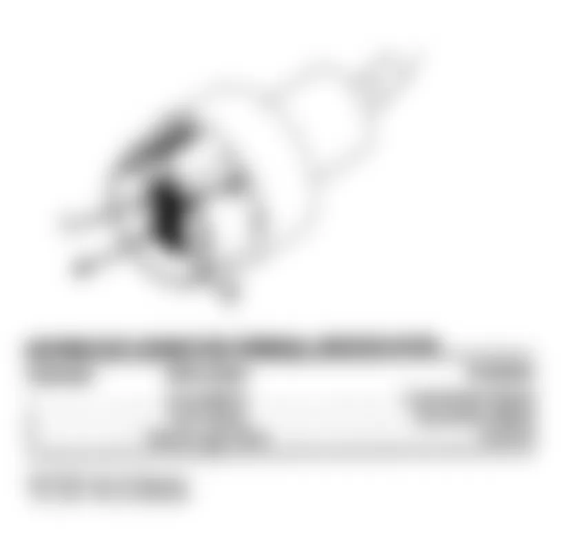
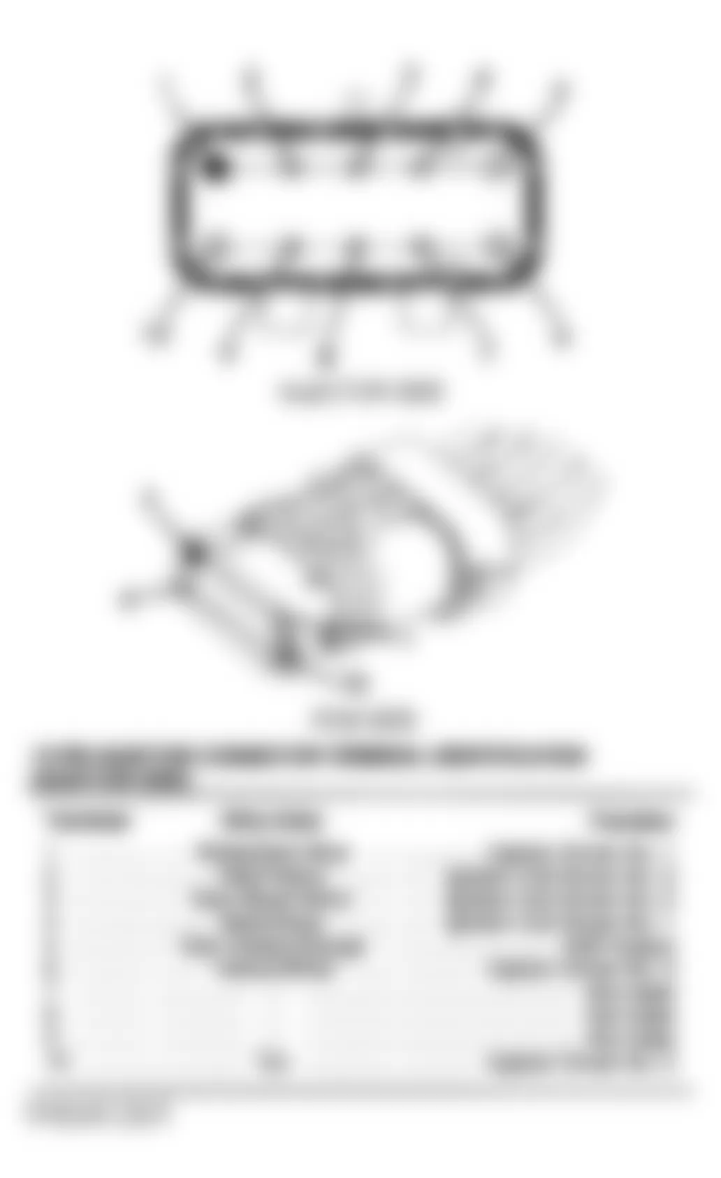
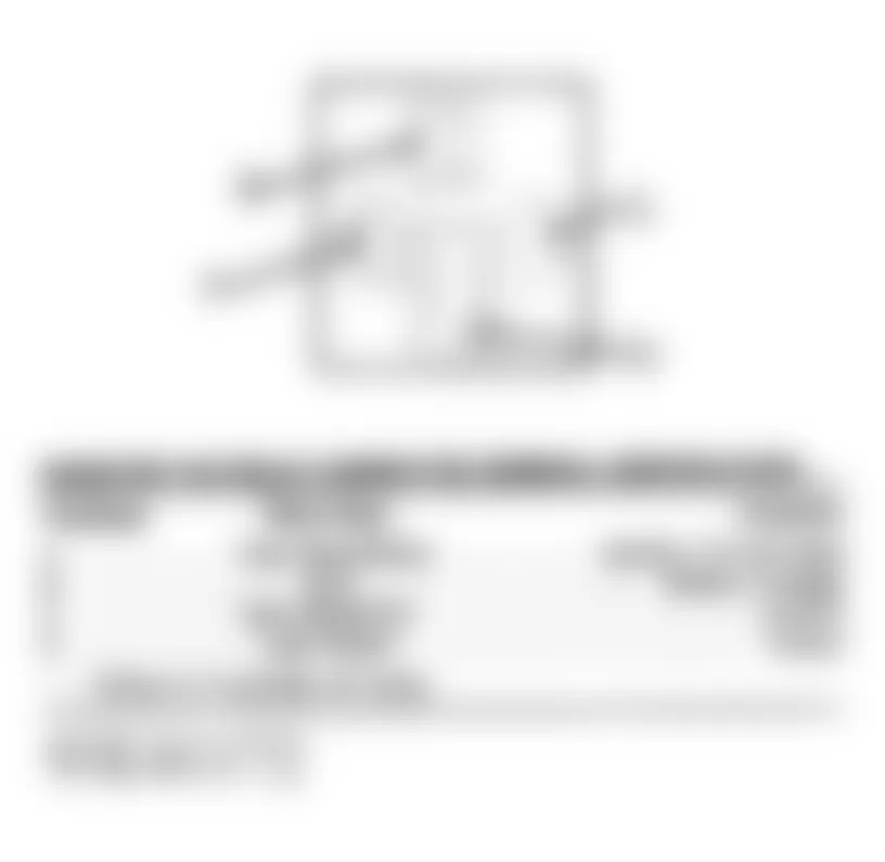
Chrysler Concorde 1993 DISTRIBUTOR CONNECTOR TERMINAL IDENTIFICATION
Terminal Wire Color Function 1 Gray/Black Crankshaft Signal 2 Tan/Yellow Camshaft Signal 3 Black/Light Blue Ground
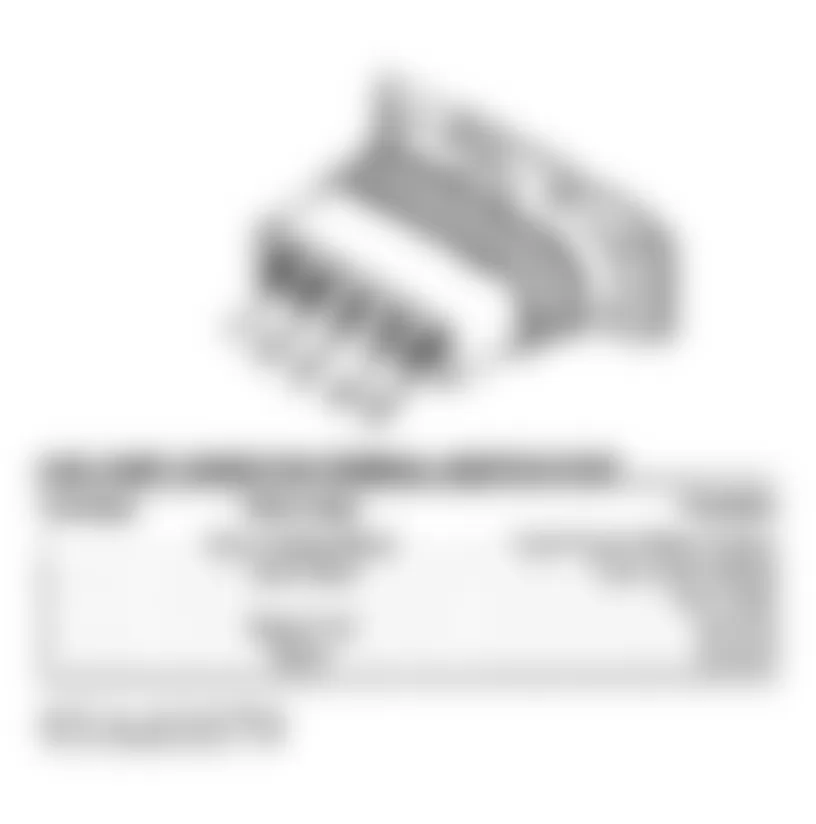
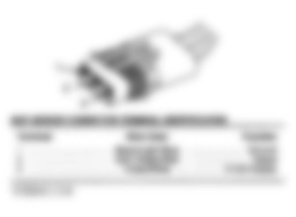
Fig. 5: Chrysler Concorde 1993 - Component Locations - Distributor Connector Terminal ID
Chrysler Concorde 1993 ENGINE TEMP COOLANT (ECT) SENSOR CONNECTOR TERMINAL ID
Terminal Wire Color Function 1 Tan/Black Signal 2 Black/Light Blue Ground
Chrysler Concorde 1993 EVAPORATIVE PURGE SOLENOID CONNECTOR TERMINAL ID
Terminal Wire Color Function 1 Pink/Black Control 2 Light Green/Black Ignition 12-Volt Feed
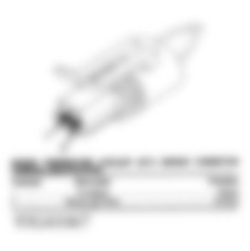
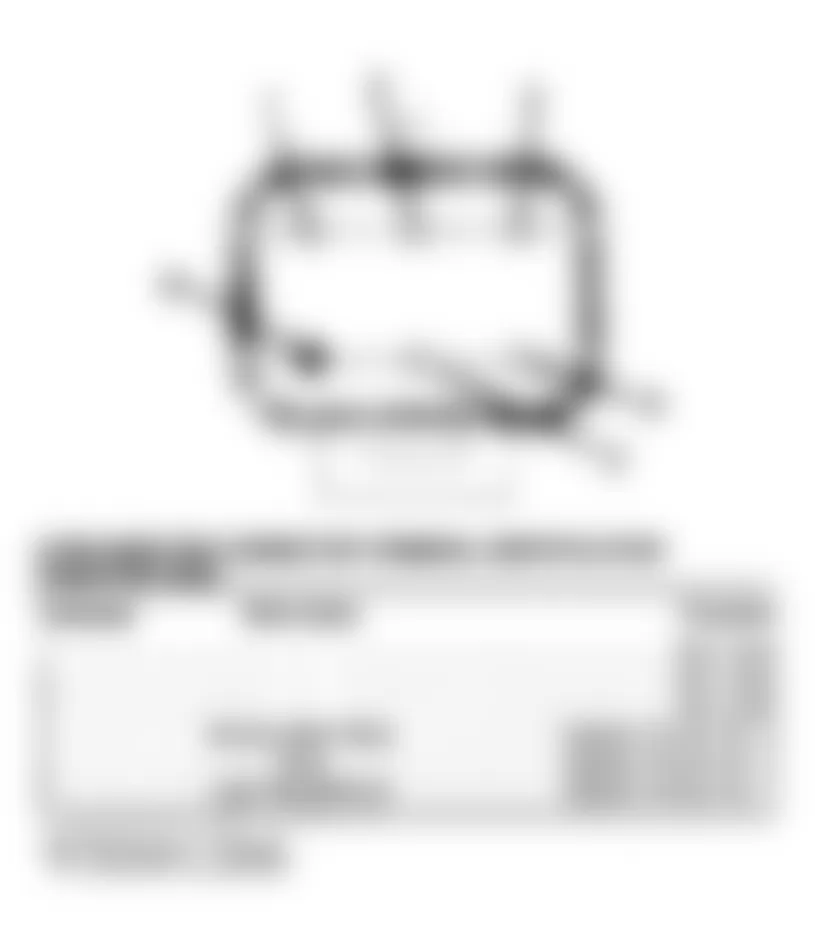
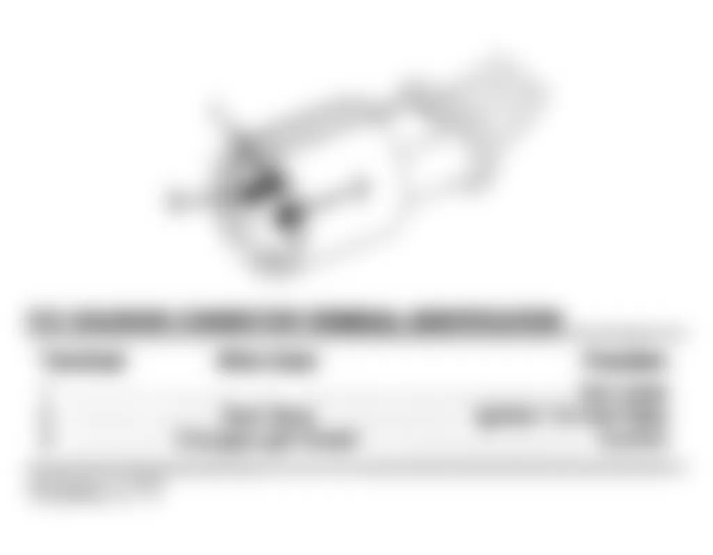
Chrysler Concorde 1993 FLEXIBLE FUEL SENSOR CONNECTOR TERMINAL IDENTIFICATION (LH BODY)
Terminal Wire Color Function 1 Black/Red Signal 2 Black/Light Blue Ground 3 Orange 8-Volt Supply
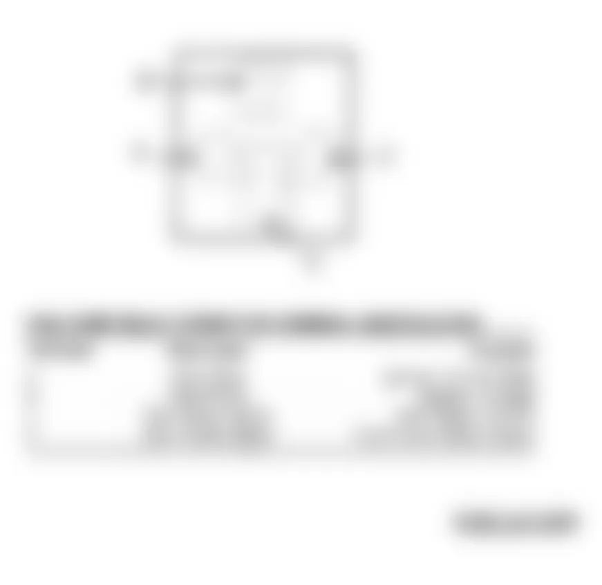
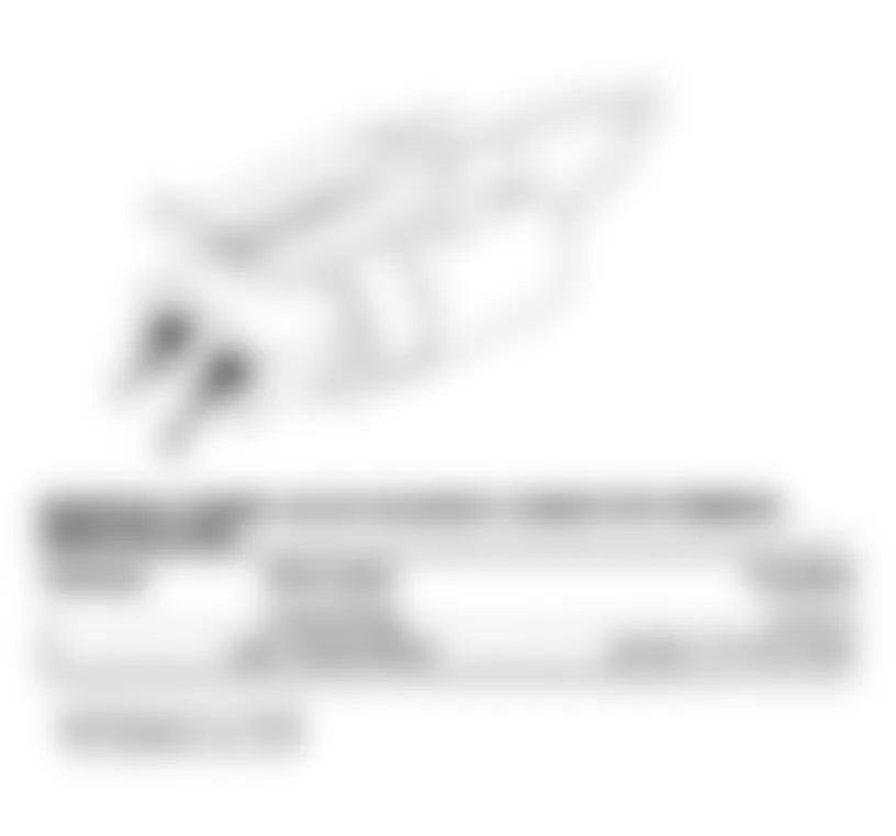
Fig. 8: Chrysler Concorde 1993 - Component Locations - Flexible Fuel Sensor Connector Terminal ID
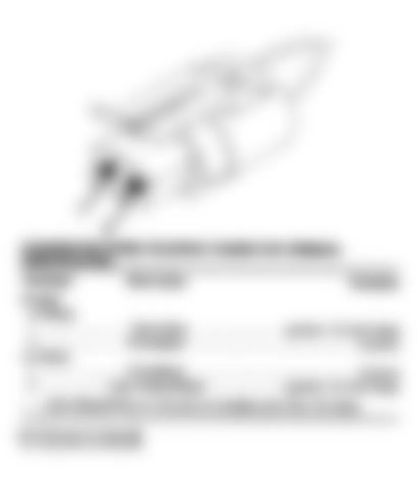
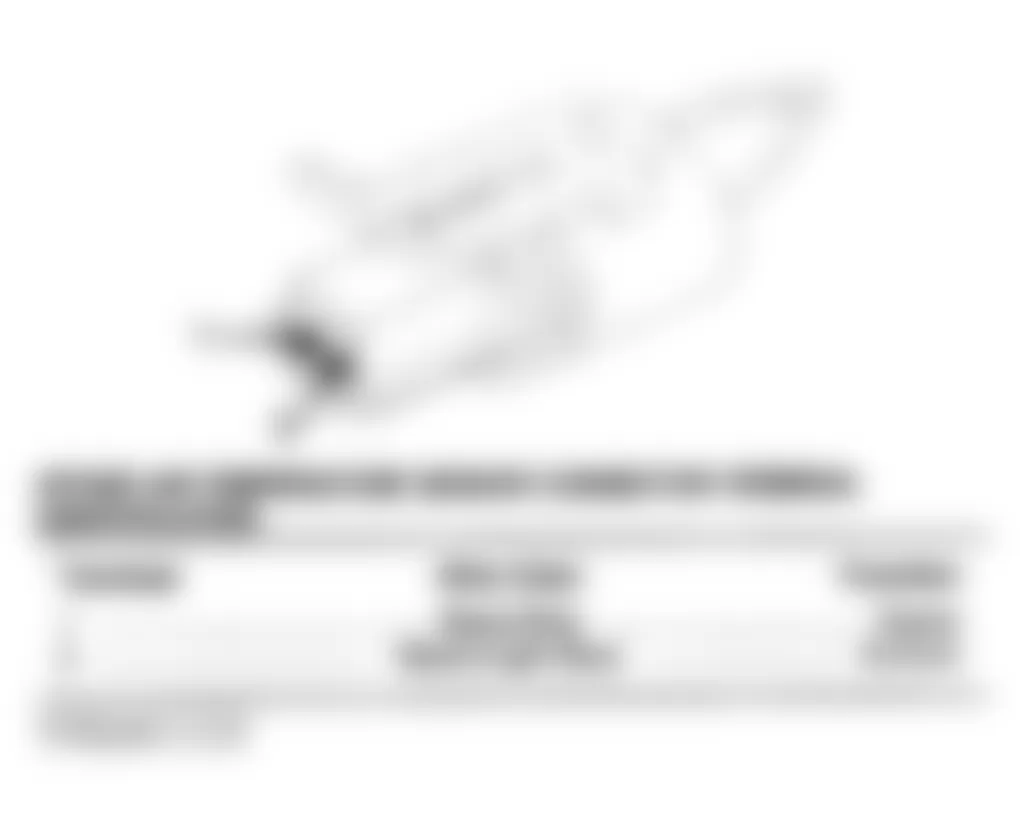
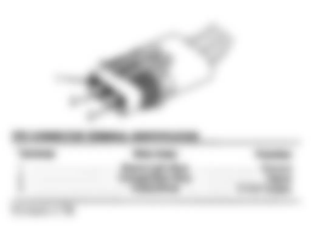
Chrysler Concorde 1993 FUEL PUMP CONNECTOR TERMINAL IDENTIFICATION
Terminal Wire Color Function 1 Dark Green/Black Fuel Pump Relay Output 2 Dark Blue Fuel Level Sense 3 Not Used Not Used 4 Black/Tan Ground 5 Black Ground
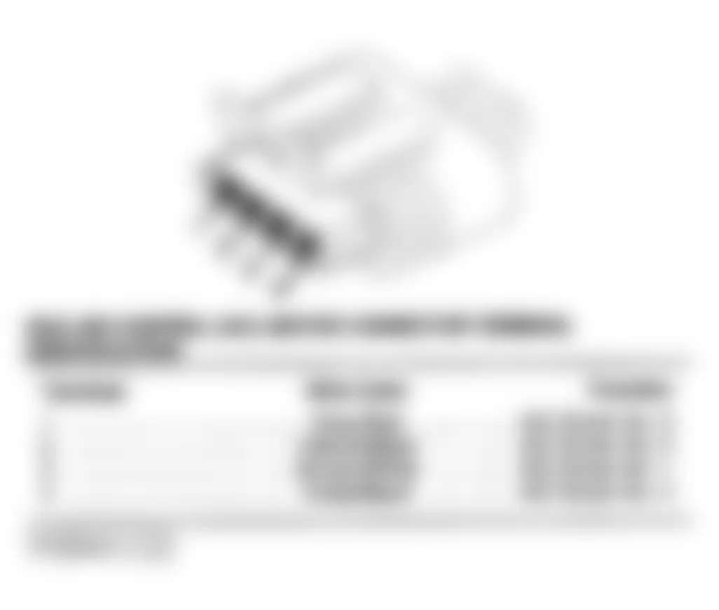
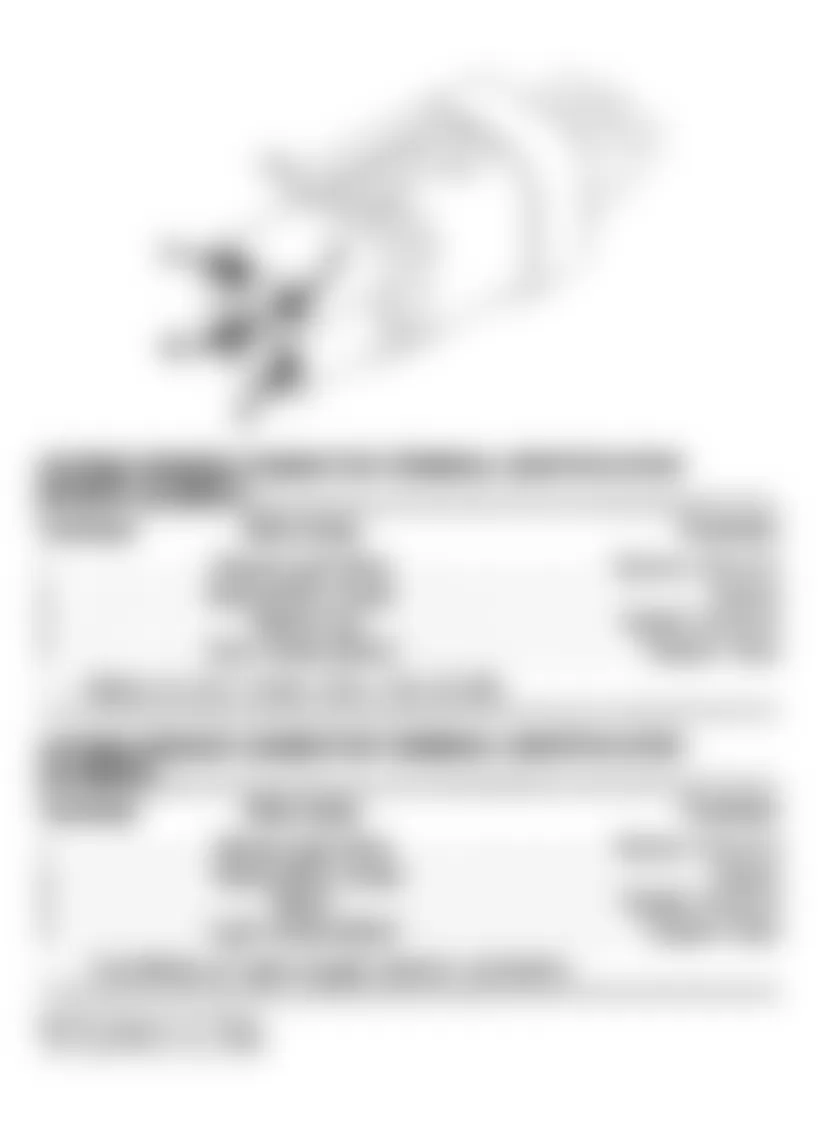
Fig. 9: Chrysler Concorde 1993 - Component Locations - Fuel Pump Connector Terminal ID (LH Body)
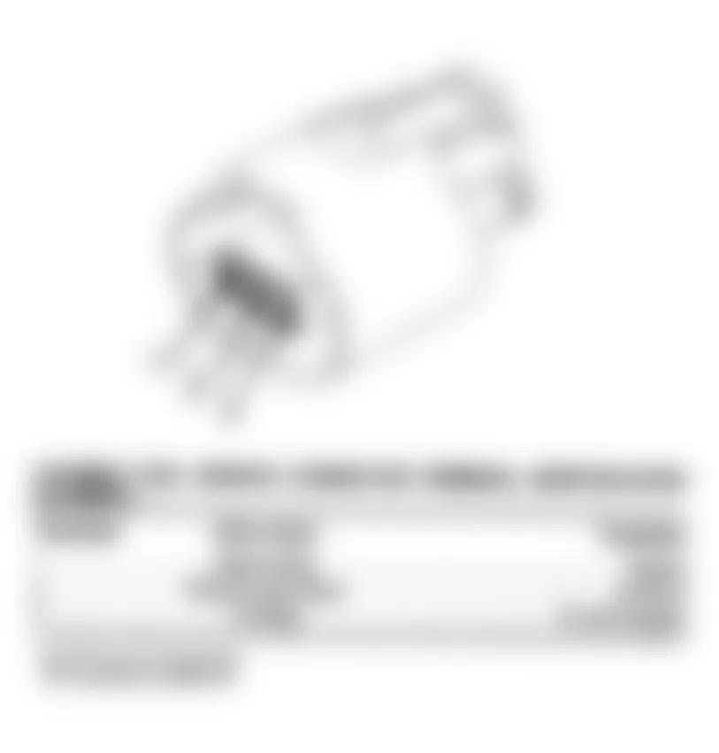
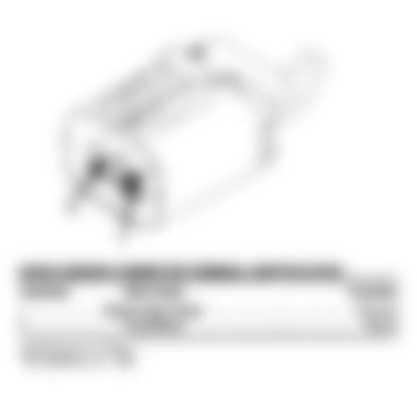
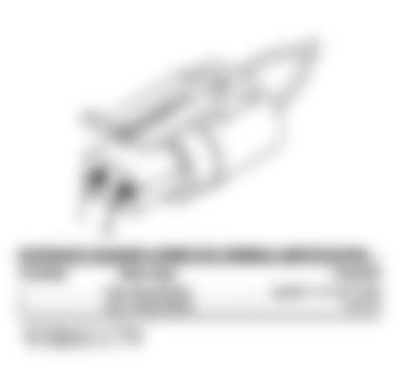
Chrysler Concorde 1993 FUEL PUMP RELAY CONNECTOR TERMINAL IDENTIFICATION
Terminal Wire Color Function A Dark Blue Ignition 12-Volt Feed B Red/White Battery Voltage C Dark Blue/Yellow ASD Relay Control D Dark Green/Black Fuel Pump Relay Output
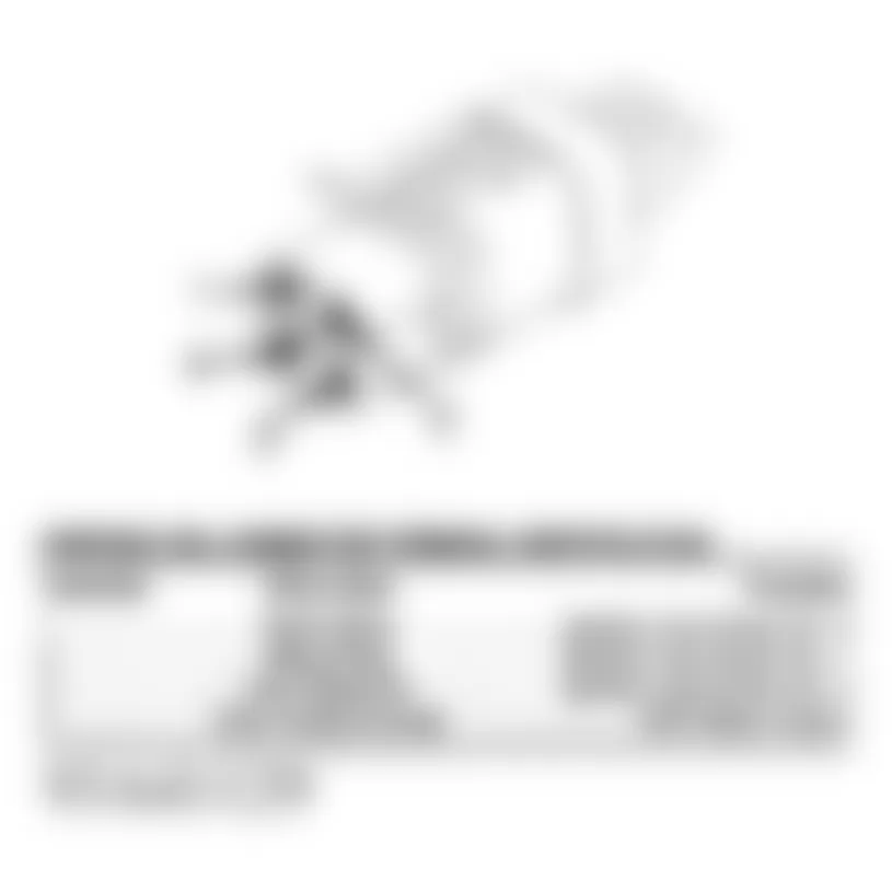
Fig. 10: Chrysler Concorde 1993 - Component Locations - Fuel Pump Relay Connector Terminal ID (3.3L)
Chrysler Concorde 1993 IDLE AIR CONTROL (IAC) MOTOR CONNECTOR TERMINAL IDENTIFICATION
Terminal Wire Color Function 1 Gray/Red IAC Driver No. 3 2 Yellow/Black IAC Driver No. 2 3 Brown/White IAC Driver No. 1 4 Violet/Black IAC Driver No. 4
Chrysler Concorde 1993 IGNITION COIL CONNECTOR TERMINAL IDENTIFICATION
Terminal Wire Color Function 1 Red/Yellow Ignition Coil Driver No. 3 2 Black/Gray Ignition Coil Driver No. 1 3 Dark Blue/Tan Ignition Coil Driver No. 2 4 Dark Green/Orange ASD Relay Output
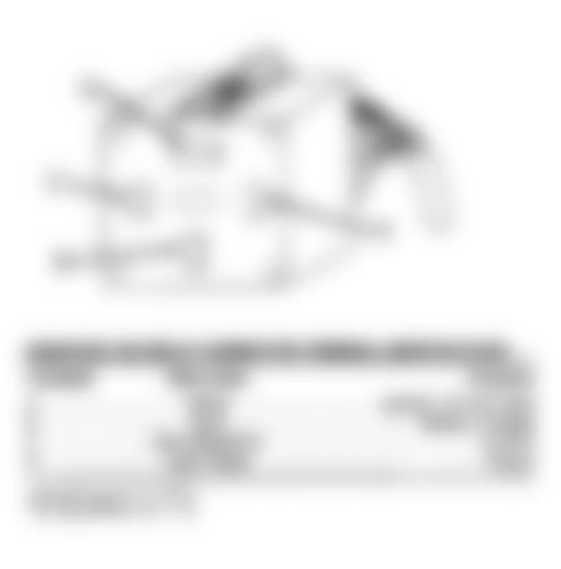
Fig. 12: Chrysler Concorde 1993 - Component Locations - Ignition Coil Connector Terminal ID
Chrysler Concorde 1993 10-PIN INJECTOR CONNECTOR TERMINAL ID (INJECTOR SIDE)
Terminal Wire Color Function 1 White/Dark Blue Injector Driver No. 1 2 Red/Yellow Ignition Coil Driver No. 3 3 Dark Blue/Yellow Ignition Coil Driver No. 2 4 Black/Gray Ignition Coil Driver No. 1 5 Dark Green/Orange ASD Output 6 Yellow/White Injector Driver No. 3 7 Not Used Not Used 8 Not Used Not Used 9 Not Used Not Used 10 Tan Injector Driver No. 2
Fig. 13: Chrysler Concorde 1993 - Component Locations - 10-Pin Injector Connector Terminal ID (3.3L)
Chrysler Concorde 1993 6-PIN INJECTOR CONNECTOR TERMINAL ID (INJECTOR SIDE)
Terminal Wire Color Function 1 Not Used Not Used 2 Not Used Not Used 3 Not Used Not Used 4 Brown/Dark Blue Injector Driver No. 6 5 Gray Injector Driver No. 5 6 Light Blue/Brown Injector Driver No. 4
Fig. 14: Chrysler Concorde 1993 - Component Locations - 6-Pin Injector Connector Terminal ID (3.3L)
Chrysler Concorde 1993 INTAKE AIR TEMPERATURE SENSOR CONNECTOR TERMINAL ID
Terminal Wire Color Function 1 Black/Red Signal 2 Black/Light Blue Ground
Chrysler Concorde 1993 KNOCK SENSOR CONNECTOR TERMINAL IDENTIFICATION
Terminal Wire Color Function 1 Black/Light Green Ground 2 Gray/Black Signal
Fig. 16: Chrysler Concorde 1993 - Component Locations - Knock Sensor Connector Terminal ID (LH Body)
Chrysler Concorde 1993 MAP SENSOR CONNECTOR TERMINAL IDENTIFICATION
Terminal Wire Color Function 1 Black/Light Blue Ground 2 Dark Green/Red Signal 3 Violet/White 5-Volt Supply
Chrysler Concorde 1993 MANIFOLD TUNING VALVE SOLENOID CONNECTOR TERMINAL IDENTIFICATION
Terminal Wire Color Function 1 Violet/White Control 2 Light Green/Black Ignition 12-Volt Feed
Chrysler Concorde 1993 OXYGEN SENSOR CONNECTOR TERMINAL IDENTIFICATION (LH BODY)
Terminal Wire Color Function 1 Black/Light Blue Sensor Ground 2 (1) Black/Dark Green Signal 3 Black Heater Ground 4 Light Green/Black Heater Feed
(1) Tan/White on right oxygen sensor connector.
Fig. 19: Chrysler Concorde 1993 - Component Locations - Oxygen Sensor Connector Terminal ID
Chrysler Concorde 1993 RADIATOR FAN RELAY CONNECTOR TERMINAL IDENTIFICATION (3.3L)
Terminal Wire Color Function A White Ignition 12-Volt Feed B Gray Battery Voltage C Dark Blue/Pink Control D Light Green Output
Chrysler Concorde 1993 RADIATOR FAN RELAY CONNECTOR TERMINAL IDENTIFICATION (3.5L)
Terminal Wire Color Function A Dark Blue Ignition 12-Volt Feed B Gray Battery Voltage C Dark Blue/Pink Control D Light Green Output
Chrysler Concorde 1993 TORQUE CONVERTER CLUTCH SOLENOID CONNECTOR TERMINAL ID
Terminal Wire Color Function 1 Not Used Not Used 2 Dark Blue Ignition 12-Volt Feed 3 Orange/Light Green Control
Chrysler Concorde 1993 THROTTLE POSITION SENSOR (TPS) CONNECTOR TERMINAL ID
Terminal Wire Color Function 1 Black/Light Blue Ground 2 Orange/Dark Blue Signal 3 Violet/White 5-Volt Supply
Chrysler Concorde 1993 WASTEGATE SOLENOID CONNECTOR TERMINAL IDENTIFICATION
Terminal Wire Color Function 1 Dark Blue/White Ignition 12-Volt Feed 2 Light Green/Black Control
Fig. 24: Chrysler Concorde 1993 - Component Locations - Wastegate Solenoid Connector Terminal ID

CAUTION: When battery is disconnected, vehicle computer and energy systems may lose memory data. Driveability problems may exist until computer systems have completed a relearn cycle. See COMPUTER RELEARN PROCEDURES article in GENERAL INFORMATION before disconnecting battery.
Chrysler Concorde 1993 - SELF-DIAGNOSTIC TESTS
NOTE: In following tests, illustrations are courtesy of Chrysler Corp.
Chrysler Concorde 1993 - FAULT CODE TESTS TEST FC-1A - CHECKING SYSTEM FOR FAULT CODES
NOTE: For connector terminal identification, see CONNECTOR IDENTIFICATION . For wiring diagram, see WIRING DIAGRAMS at the end of this article.
NOTE: Battery must be fully charged before proceeding.
- Attempt to start engine. If necessary, crank engine for up to 10 seconds. Connect DRB-II to data link connector. Record DRB-II fault messages. If DRB-II screen displays NO RESPONSE, go to TEST NS-6A.
- If DRB-II has a blank screen or displays RAM TEST FAILURE, CARTRIDGE ERROR, KEY PAD TEST FAILURE, or LOW OR HIGH BATTERY, this indicates a DRB-II failure. To diagnose and correct these conditions, see see TESTS W/CODES - 3.3L/3.5L article.
- If fault messages are displayed, refer to fault code list. See DTC & DRB-II FAULT MESSAGES table. If DRB-II does not display any fault messages, refer to one of the following: for driveability problems, go to TEST NF-1A. For no-start problems, go to TEST NS-1A.
Chrysler Concorde 1993 DTC & DRB-II FAULT MESSAGES
DTC DRB-II Message Perform Test No. Code 11 NO CRANK REFERENCE SIGNAL AT PCM FC-2A Code 54 NO CAM SYNC SIGNAL AT PCM FC-3A Code 13 NO CHANGE IN MAP FROM START TO RUN FC-4A Code 14 MAP SENSOR VOLTAGE TOO LOW FC-5A Code 14 MAP SENSOR VOLTAGE TOO HIGH FC-6A Code 15 NO VEHICLE SPEED SENSOR SIGNAL FC-7A Code 21 LEFT O2S STAYS AT CENTER FC-8A Code 21 RIGHT O2S STAYS AT CENTER FC-9A Code 21 LEFT O2S SHORTED TO VOLTAGE FC-10A Code 21 RIGHT O2S SHORTED TO VOLTAGE FC-11A Code 52 LEFT O2S STAYS ABOVE CENTER (RICH) FC-12A Code 52 RIGHT O2S STAYS ABOVE CENTER (RICH) FC-13A Code 51 LEFT O2S STAYS BELOW CENTER (LEAN) FC-14A Code 51 RIGHT O2S STAYS BELOW CENTER (LEAN) FC-15A Code 22 ECT SENSOR VOLTAGE TOO HIGH FC-16A Code 22 ECT SENSOR VOLTAGE TOO LOW FC-17A Code 23 INTAKE AIR TEMPERATURE SENSOR VOLTAGE LOW FC-18A Code 23 INTAKE AIR TEMPERATURE SENSOR VOLTAGE HIGH FC-19A Code 24 THROTTLE POSITION SENSOR VOLTAGE HIGH FC-20A Code 24 THROTTLE POSITION SENSOR VOLTAGE LOW FC-21A Code 25 IDLE AIR CONTROL MOTOR CIRCUITS FC-22A Code 27 INJECTOR #1 CONTROL CIRCUIT FC-23A Code 27 INJECTOR #2 CONTROL CIRCUIT FC-24A Code 27 INJECTOR #3 CONTROL CIRCUIT FC-25A Code 27 INJECTOR #4 CONTROL CIRCUIT FC-26A Code 27 INJECTOR #5 CONTROL CIRCUIT FC-27A Code 27 INJECTOR #6 CONTROL CIRCUIT FC-28A Code 31 EVAP PURGE SOLENOID CONTROL CIRCUIT FC-29A Code 32 EGR SOLENOID CONTROL CIRCUIT FC-30A Code 32 EGR SYSTEM FAILURE FC-31A Code 16 KNOCK SENSOR #1 CIRCUIT FC-32A Code 16 KNOCK SENSOR #2 CIRCUIT FC-33A Code 33 A/C CLUTCH RELAY CIRCUIT FC-34A Code 33 A/C PRESSURE SENSOR HIGH FC-35A Code 33 A/C PRESSURE SENSOR LOW FC-36A Code 35 LOW SPEED FAN CTRL RELAY CIRCUIT FC-37A Code 35 HIGH SPEED FAN CTRL RELAY CIRCUIT FC-38A Code 42 AUTO SHUTDOWN RELAY CONTROL CIRCUIT FC-39A Code 43 IGNITION COIL #1 PRIMARY CIRCUIT FC-40A Code 43 IGNITION COIL #2 PRIMARY CIRCUIT FC-41A Code 43 IGNITION COIL #3 PRIMARY CIRCUIT FC-42A Code 65 MANIFOLD TUNE VALVE SOLENOID CIRCUIT FC-43A Code 66 NO CCD MESSAGE FROM TCM FC-44A Code 66 NO CCD MESSAGE FROM BODY CONTROL MODULE FC-45A Code 62 PCM FAILURE SRI MILES NOT STORED FC-46A Code 63 PCM FAILURE EEPROM WRITE DENIED FC-47A Code 17 ENGINE IS COLD TOO LONG (1) Code 53 INTERNAL PCM FAILURE (2) Code 44 BATTERY TEMP SENSOR VOLTS OUT OF LIMIT (3) Code 47 CHARGING SYSTEM VOLTAGE TOO LOW (3) Code 46 CHARGING SYSTEM VOLTAGE TOO HIGH (3) Code 34 SPEED CONTROL SOLENOID CIRCUITS (4) ..... SPEED CONTROL SWITCH ALWAYS HIGH (4) ..... SPEED CONTROL SWITCH ALWAYS LOW (4) Code 77 SPEED CONTROL POWER RELAY CIRCUIT (4)
(1) If engine temperature does not reach 176?F (80?C) after driving 20 minutes, check cooling system. Fault may also set in error during very cold slow speed driving.
(2) Replace Powertrain Control Module (PCM) and perform VERIFICATION PROCEDURE VER-1.
(3) - appropriate ALTERNATORS & REGULATORS article in the ELECTRICAL Section.
(4) - appropriate CRUISE CONTROL SYSTEM article in ACCESSORIES/SAFETY EQUIPMENT Section.
Chrysler Concorde 1993 - TEST FC-2A - NO CRANK REFERENCE SIGNAL AT PCM (DTC 11)
NOTE: For connector terminal identification, see CONNECTOR IDENTIFICATION . For appropriate wiring diagram, see WIRING DIAGRAMS at end of article.
- Using DRB-II, erase faults. Attempt to start engine. If necessary, crank engine for at least 10 seconds. Read DRB-II faults. If DRB-II displays NO CRANK REFERENCE SIGNAL AT PCM, go to step 5). If DRB-II does not display NO CRANK REFERENCE SIGNAL AT PCM, go to next step.
- At this time, the condition required to set fault is not present. NO CRANK REFERENCE SIGNAL AT PCM fault sets if powertrain control module does not see crank signal with cam signal present. Possible causes are: open 8-volt power supply at crankshaft position sensor, open or shorted crankshaft position sensor signal wire, open crankshaft position sensor ground, failed crankshaft position sensor, improperly adjusted crankshaft position sensor, failed Powertrain Control Module (PCM), or failed Transmission Control Module (TCM).
- Inspect crankshaft position sensor wiring and connectors. Clean and repair wiring and connectors as required. Perform TEST VER-2. If wiring and connectors are okay, start engine. Wiggle wiring harness from crankshaft position sensor to PCM.
- If engine misses or stalls when wiring harness is wiggled, repair wiring harness where wiggling caused problem. Perform TEST VER-2. If engine does not miss or stall when wiring harness is wiggled, see INACTIVE FAULT CONDITION . is complete. Perform TEST VER-2.
- If DRB-II displayed NO CRANK REFERENCE SIGNAL AT PCM instep 1), turn ignition off. Disconnect crankshaft position sensor connector. Place DRB-II in ohmmeter mode. Using DRB-II, check resistance of crankshaft position sensor connector 8-volt power supply wire (Orange wire).
- If resistance is less than 5 ohms, repair 8-volt power supply wire for short to ground. If resistance is more than 5 ohms, turn ignition on. Place DRB-II in voltmeter mode.
- Using DRB-II, check voltage of crankshaft position sensor connector 8-volt power supply wire (Orange wire). If voltage is less than 7 volts, go to TEST FC-2B. If voltage is more than 7 volts, turn ignition off. Connect one end of a jumper wire to crankshaft position sensor connector signal wire (Gray/Black wire).
- Turn ignition on. Read DRB-II DIS signal status while tapping other end of jumper wire to crankshaft position sensor connector ground wire (Black/Light Blue wire).
- If DRB-II displays CRANK ONLY, replace crankshaft position sensor. Perform TEST VER-2. If DRB-II does not display CRANK ONLY, turn ignition off. Place DRB-II in ohmmeter mode.
- Using DRB-II, check resistance of crankshaft position sensor connector sensor ground wire (Black/Dark Blue wire). If resistance is more than 5 ohms, repair sensor ground wire for an open to harness splice. Perform TEST VER-2. If resistance is less than 5 ohms, go to next step.
- Disconnect PCM connector. Inspect PCM connector. Repair any terminals that are damaged, pushed out or miswired. Perform TEST VER-2. If PCM connector is okay, go to next step.
- Using an external ohmmeter, check resistance of signal wire (Gray/Black wire) between crankshaft position sensor connector and PCM connector terminal No. 24. If resistance is more than 5 ohms, repair crankshaft position sensor signal wire for an open. Perform TESTVER-2.
- If resistance is less than 5 ohms, place DRB-II in ohmmeter mode. Using DRB-II, check resistance of PCM connector terminal No. 24, signal wire (Gray/Black wire). If resistance is more than 5 ohms, replace PCM. Perform TEST VER-2.
- If resistance is less than 5 ohms, disconnect TCM connector. Using DRB-II, check resistance of PCM connector terminal No. 24, signal wire (Gray/Black wire).
- If resistance is more than 5 ohms, replace TCM. Perform TEST VER-2. If resistance is less than 5 ohms, repair signal wire for short to ground. Perform TEST VER-2.
Chrysler Concorde 1993 - TEST FC-2B - NO CRANK REFERENCE SIGNAL AT PCM
NOTE: For connector terminal identification, see CONNECTOR IDENTIFICATION . For appropriate wiring diagram, see WIRING DIAGRAMS at end of article.
- Turn ignition off. Disconnect Powertrain Control Module (PCM) connector. Inspect PCM connector. Clean and repair wiring and connectors as required. Perform TEST VER-2. If PCM connector is okay, go to next step.
- Using an external ohmmeter, check resistance of 8-volt power supply wire (Orange wire) between crankshaft position sensor connector and PCM connector terminal No. 7.
- If resistance is more than 5 ohms, repair 8-volt power supply wire for an open. If resistance is less than 5 ohms, replace PCM. Perform TEST VER-2.
Chrysler Concorde 1993 - TEST FC-3A - NO CAM SYNC SIGNAL AT PCM (DTC 54)
NOTE: For connector terminal identification, see CONNECTOR IDENTIFICATION . For appropriate wiring diagram, see WIRING DIAGRAMS at end of article.
- Using DRB-II, erase faults. Attempt to start engine. If necessary, crank engine for at least 10 seconds. Read faults. If DRB-II displays NO CAM SYNC SIGNAL AT PCM, go to step 5). If DRB-II does not display NO CAM SYNC SIGNAL AT PCM, go to next step.
- At this time, the condition required to set fault is not present. NO CAM SYNC SIGNAL AT PCM fault sets if Powertrain Control Module (PCM) does not see cam signal with crank signal present. Possible causes are: open 8-volt power supply at camshaft position sensor, open or shorted camshaft position sensor signal wire, open camshaft position sensor ground, failed camshaft position sensor, improperly adjusted camshaft position sensor, or failed PCM.
- Inspect camshaft position sensor wiring and connectors. Repair as required. Perform TEST VER-2. If wiring and connectors are okay, start engine. Wiggle wiring harness from camshaft position sensor to PCM. If engine stalls when wiring harness is wiggled, repair area where wiggling caused problem to appear. Perform TEST VER-2.
- If engine does not stall when wiring harness is wiggled, see INACTIVE FAULT CONDITION . Perform TEST VER-2.
- If DRB-II displayed NO CAM SYNC SIGNAL AT PCM in step 1), turn ignition off. Disconnect camshaft position sensor connector. Place DRB-II in ohmmeter mode. Using DRB-II, check resistance of camshaft position sensor connector 8-volt power supply wire (Orange wire).
- If resistance is less than 5 ohms, repair 8-volt power supply wire for short to ground. Perform TEST VER-2. If resistance is more than 5 ohms, turn ignition on.
- Place DRB-II in voltmeter mode. Using DRB-II, check voltage of camshaft position sensor connector 8-volt power supply wire (Orange wire). If voltage is less than 7 volts, go to TEST FC-3B. If voltage is more than 7 volts, turn ignition off.
- Using a jumper wire, connect one end of jumper wire to camshaft position sensor connector signal wire (Tan/Yellow wire). Turn ignition on. Read DRB-II DIS signal status. While observing DIS signal status, connect other end of jumper wire to camshaft position sensor connector ground wire (Black/Light Blue wire).
- If DRB-II displays CAM ONLY, replace camshaft position sensor. Perform TEST VER-2. If DRB-II does not display CAM ONLY, turn ignition off. Place DRB-II in ohmmeter mode.
- Using DRB-II, check resistance of camshaft position sensor ground wire (Black/Light Blue wire). If resistance is more than 5 ohms, repair camshaft position sensor ground wire for an open to harness splice. Perform TEST VER-2. If resistance is less than 5 ohms, go to next step.
- Disconnect PCM connector. Inspect PCM connector terminals. Repair as required. Perform TEST VER-2. If PCM connector is okay, go to next step.
- Using an external ohmmeter, check resistance of signal wire (Tan/Yellow wire) between camshaft position sensor connector and PCM connector terminal No. 44. If resistance is more than 5 ohms, repair camshaft position sensor signal wire for an open. Perform TEST VER-2.
- If resistance is less than 5 ohms, place DRB-II in ohmmeter mode. Using DRB-II, check resistance of PCM connector terminal No. 44, signal wire (Tan/Yellow wire). If resistance is more than 5 ohms, replace PCM. If resistance is less than 5 ohms, repair camshaft position sensor signal wire for short to ground. Perform TEST VER-2.
Chrysler Concorde 1993 - TEST FC-3B - NO CAM SYNC SIGNAL AT PCM
NOTE: For connector terminal identification, see CONNECTOR IDENTIFICATION . For appropriate wiring diagram, see WIRING DIAGRAMS at end of article.
- Turn ignition off. Disconnect Powertrain Control Module (PCM) connector. Inspect PCM connector. Repair as required. Perform TEST VER-2. If PCM connector is okay, go to next step.
- Using an external ohmmeter, check resistance of 8-volt power supply wire (Orange wire) between camshaft position sensor connector and PCM connector terminal No. 7.
- If resistance is more than 5 ohms, repair 8-volt power supply wire for an open. Perform TEST VER-2. If resistance is less than 5 ohms, replace PCM. Perform TEST VER-2.
Chrysler Concorde 1993 - TEST FC-4A - NO CHANGE IN MAP FROM START TO RUN (DTC 13)
NOTE: For connector terminal identification, see CONNECTOR IDENTIFICATION . For appropriate wiring diagram, see WIRING DIAGRAMS at end of article.
- Using DRB-II, erase faults. Start engine. Allow engine to run for 30 seconds. Read faults. If DRB-II displays NO CHANGE IN MAP FROM START TO RUN, go to next step. If DRB-II does not display NO CHANGE IN MAP FROM START TO RUN, go to step 4).
- Turn ignition off. Disconnect MAP sensor connector. Turn ignition on. Place DRB-II in voltmeter mode. Using DRB-II, check voltage of MAP sensor connector 5-volt supply wire (Violet/White wire).
- If voltage is less than 4.5 volts, repair 5-volt supply wire to MAP sensor. Perform TEST VER-2. If voltage is more than 4.5 volts, replace MAP sensor. Perform TEST VER-2.
- If DRB-II did not display NO CHANGE IN MAP FROM START TO RUN in step 1), start engine. Using DRB-II, set engine speed to 1500 RPM. With engine speed at 1500 RPM, read MAP sensor vacuum.
- While watching DRB-II display, snap throttle open and closed. If vacuum does not drop rapidly to zero in. Hg, go to step 7). If vacuum drops rapidly to zero in. Hg, go to next step.
- At this time, the condition required to set the fault is not present. NO CHANGE IN MAP FROM START TO RUN fault sets if too small a difference is seen between barometric pressure at key on and manifold vacuum after start up. Possible causes are: restricted or leaking vacuum/pressure to MAP sensor, ice in sensor or passage, or MAP sensorfailure.
- If vacuum did not drop rapidly to zero in. Hg, in step 5), remove MAP sensor and check for restriction. If a restriction is present, remove restriction and reinstall MAP sensor. Perform TEST VER-2. If restriction is not present, replace MAP sensor. Perform TEST VER-2.
Chrysler Concorde 1993 - TEST FC-5A - MAP SENSOR VOLTAGE TOO LOW (DTC 14)
NOTE: For connector terminal identification, see CONNECTOR IDENTIFICATION . For appropriate wiring diagram, see WIRING DIAGRAMS at end of article.
- Using DRB-II, read MAP sensor voltage with engine running. If MAP sensor voltage is less than 0.2 volt, go to step 6). If MAP sensor voltage is more than 0.2 volt, turn ignition on (engine off).
- Using DRB-II, read MAP sensor voltage. If MAP sensor voltage is less than 1.2 volts, go to step 6). If MAP sensor voltage is more than 1.2 volts, wiggle MAP sensor connector and harness while observing DRB-IIdisplay.
- If MAP sensor voltage changes when MAP sensor connector and harness are wiggled, repair harness or connector that caused the voltage change. Perform TEST VER-2. If MAP sensor voltage does not change when MAP sensor connector and harness are wiggled, go to next step.
- At this time, the condition required to set the fault is not present. MAP SENSOR VOLTAGE TOO LOW fault sets if MAP sensor output voltage is less than 1.2 volts at start, or less than 0.2 volt with engine running. Engine speed must be more than 400 RPM, but less than 1500 RPM, and TPS voltage less than one volt. Possible causes are: MAP sensor signal wire shorted to ground, MAP sensor shorted internally, or loss of MAP sensor 5-volt supply wire.
- Inspect MAP sensor wiring and connectors. Repair as required. Perform TEST VER-2. If wiring and connectors are okay, see INACTIVE FAULT CONDITION . Perform TEST VER-2.
- Disconnect MAP sensor connector. Using DRB-II, read MAP sensor voltage. If MAP sensor voltage is more than 4 volts, replace MAP sensor. Perform TEST VER-2. If MAP sensor voltage is less than 4 volts, turn ignition off.
- Disconnect Powertrain Control Module (PCM). Place DRB-II in volt-meter mode. Using DRB-II, check voltage of MAP sensor signal circuit (Dark Green/Red wire). If resistance is less than 10 ohms, repair MAP sensor signal wire for short to ground. Perform TEST VER-2. If resistance is more than 10 ohms, replace PCM. Perform TEST VER-2.
Chrysler Concorde 1993 - TEST FC-6A - MAP SENSOR VOLTAGE TOO HIGH (DTC 14)
NOTE: For connector terminal identification, see CONNECTOR IDENTIFICATION . For appropriate wiring diagram, see WIRING DIAGRAMS at end of article.
- Start engine. Using DRB-II, read MAP sensor voltage. If MAP sensor voltage is more than 4.6 volts, go to step 5). If MAP sensor voltage is less than 4.6 volts, wiggle MAP sensor connector and harness while observing DRB-II display.
- If MAP sensor voltage changes when MAP sensor connector and harness are wiggled, repair harness or connector that caused voltage change. Perform TEST VER-2. If MAP sensor voltage does not change when MAP sensor connector and harness are wiggled, go to next step.
- At this time, the condition required to set fault is not present. MAP SENSOR VOLTAGE TOO HIGH fault sets if MAP sensor output voltage is more than 4.6 volts at start or with engine running. Engine speed must be more than 400 RPM, but less than 1500 RPM, and TPS voltage less than one volt. Possible causes are: MAP sensor signal wire open, MAP sensor open internally, MAP sensor ground wire open, or MAP sensor signal wire shorted to voltage.
- Inspect MAP sensor wiring and connector. Repair wiring and connector as required. Perform TEST VER-2. If wiring and connectors are okay, see INACTIVE FAULT CONDITION . Perform TEST VER-2.
- If MAP sensor voltage was more than 4.6 volts in step 1), disconnect MAP sensor connector. Connect a jumper wire between MAP sensor connector signal wire (Dark Green/Red wire) and MAP sensor connector ground wire (Black/Light Blue wire). Using DRB-II, read MAP sensor voltage.
- If MAP sensor voltage is less than one volt, replace MAP sensor. Perform TEST VER-2. If MAP sensor voltage is more than one volt, move jumper wire from MAP sensor connector ground wire (Black/Light Blue wire) to engine ground.
- Read MAP sensor voltage. If voltage is less than one volt, repair open MAP sensor ground wire. Perform TEST VER-2. If voltage is more than one volt, disconnect Powertrain Control Module (PCM).
- Connect a jumper wire between PCM connector terminal No. 1, signal wire (Dark Green/Red wire) and MAP sensor connector signal wire (Dark Green/Red wire). If resistance is less than 5 ohms, replace PCM. Perform TEST VER-2. If resistance is more than 5 ohms, repair open MAP sensor signal wire. Perform TEST VER-2.
Chrysler Concorde 1993 - TEST FC-7A - NO VEHICLE SPEED SENSOR SIGNAL (DTC 15)
NOTE: For connector terminal identification, see CONNECTOR IDENTIFICATION . For appropriate wiring diagram, see WIRING DIAGRAMS at end of article.
WARNING: Keep hands and feet clear of rotating wheels.
- Raise and support vehicle under lower control arms, allowing wheels to spin free. Start engine. Using DRB-II, read vehicle speed sensor MPH. Place transmission in any forward gear. If DRB-II does not display 0 MPH, go to step 4). If DRB-II displays 0 MPH, go to next step.
- At this time, the condition required to set fault is not present. VEHICLE SPEED SENSOR SIGNAL fault sets when Powertrain Control Module (PCM) does not see a speed signal on PCM terminal No. 47, speed sensor signal wire (White/Orange wire), under road load conditions. Possible causes are: open or shorted signal wire, no signal from Transmission Control Module (TCM), failed Daytime Running Light (DRL) module, failed PCM, or failed TCM.
- Inspect wiring and connectors. Repair wiring and connectors as required. Perform TEST VER-2. If wiring and connectors are okay, see INACTIVE FAULT CONDITION . Perform TEST VER-2.
- If DRB-II did not display 0 MPH in step 1), use DRB-II to read electronic automatic transmission faults. If any of the electronic automatic transmission faults (faults 50-58) are present, repair electronic automatic transmission as necessary.
- If no electronic automatic transmission faults are present, turn ignition off. Disconnect TCM connector. Turn ignition on. Place DRB-II in volt-meter mode. Using DRB-II, check voltage of TCM connector terminal No. 58, speed sensor signal wire (White/Orange wire).
- If voltage is more than 4 volts, go to step 10). If voltage is less than 4 volts, turn ignition off. Disconnect PCM connector. If vehicle is equipped with DRL, go to TEST FC-7B. If vehicle is not equipped with DRL, go to next step.
- Using an external ohmmeter, check resistance of speed sensor signal wire (White/Orange wire) between PCM connector terminal No. 47 and TCM connector terminal No. 58.
- If resistance is more than 5 ohms, repair open speed sensor signal wire. Perform TEST VER-2. If resistance is less than 5 ohms, place DRB-II in ohmmeter mode. Using DRB-II, check resistance of PCM connector terminal No. 47, speed sensor signal wire (White/Orange wire).
- If resistance is less than 5 ohms, repair speed sensor signal wire for short to ground. Perform TEST VER-2. If resistance is more than 5 ohms, replace PCM. Perform TEST VER-2.
- If voltage was more than 4 volts in step 6), read vehicle speed MPH using DRB-II. Connect one end of a jumper wire to TCM connector terminal No. 58, speed sensor signal wire (White/Orange wire).
- While observing DRB-II vehicle speed MPH display, connect other end of jumper wire to ground. If DRB-II displays vehicle speed more than 0 MPH, replace TCM. Perform TEST VER-2. If DRB-II displays vehicle speed less than 0 MPH, turn ignition off.
- Disconnect PCM connector. Using an external ohmmeter, check resistance of speed sensor signal wire (White/Orange wire) between PCM connector terminal No. 47 and TCM connector terminal No. 58.
- If resistance is less than 5 ohms, replace PCM. Perform TEST VER-2. If resistance is more than 5 ohms, repair speed sensor signal wire for an open. Perform TEST VER-2.
Chrysler Concorde 1993 - TEST FC-7B - NO VEHICLE SPEED SENSOR SIGNAL
NOTE: For connector terminal identification, see CONNECTOR IDENTIFICATION . For appropriate wiring diagram, see WIRING DIAGRAMS at end of article.
- Place DRB-II in ohmmeter mode. Using DRB-II, check resistance of Powertrain Control Module (PCM) connector terminal No. 47, speed sensor signal wire (White/Orange wire). If resistance is more than 5 ohms, go to step 4).
- If resistance is less than 5 ohms, disconnect Daytime Running Light (DRL) module. Using DRB-II, check resistance of PCM connector terminal No. 47, speed sensor signal wire (White/Orange wire). If resistance is more than 5 ohms, replace DRL module. Perform TEST VER-2.
- If resistance is less than 5 ohms, repair speed sensor signal wire for short to ground. Perform TEST VER-2.
- If resistance was more than 5 ohms in step 1), use an external ohmmeter to check resistance of speed sensor signal wire (White/Orange wire) between PCM connector terminal No. 47 and transmission control module connector terminal No. 58.
- If resistance is more than 5 ohms, repair open speed sensor signal wire. Perform TEST VER-2. If resistance is less than 5 ohms, replace PCM. Perform TEST VER-2.
Chrysler Concorde 1993 - TEST FC-8A - LEFT O2S STAYS AT CENTER (DTC 21)
NOTE: For connector terminal identification, see CONNECTOR IDENTIFICATION . For appropriate wiring diagram, see WIRING DIAGRAMS at end of article.
- Start engine. Using DRB-II, read left O2 sensor voltage. If left O2 sensor voltage is locked on 0.5 volt, go to step 5). If left O2 sensor voltage is not locked on 0.5 volt, wiggle O2 sensor wiring while observing DRB-II display.
- If at any time O2 sensor voltage locks on 0.5 volt when wiring is wiggled, repair harness or connector that caused voltage to lock (open circuit). Perform TEST VER-2. If O2 sensor voltage does not lock on 0.5 volt when wiring is wiggled, go to next step.
- At this time, the condition required to set fault is not present. LEFT O2S STAYS AT CENTER fault sets if O2 sensor output voltage stays at 0.5 volt for 1.5 minutes with engine temperature more than 170?F (76.6?C) and engine running for 2 minutes. Possible causes are: O2 sensor circuit open or O2 sensor failure.
- Inspect O2 wiring and connectors. Repair wiring and connectors as required. Perform TEST VER-2. If wiring and connectors are okay, see INACTIVE FAULT CONDITION . Perform TEST VER-2.
- If left O2 sensor was locked on 0.5 volt in step 1), disconnect left O2 sensor connector. Place DRB-II in ohmmeter mode. Using DRB-II, check resistance of O2 sensor connector ground wire (Black/Light Blue wire).
- If resistance is more than 5 ohms, repair ground wire for an open. Perform TEST VER-2. If resistance is less than 5 ohms, go to next step.
- Connect a jumper wire between left O2 sensor connector signal wire (Black/Dark Green wire) and positive battery terminal. Using DRB-II, read left O2 sensor voltage. If voltage is more than one volt, replace left O2 sensor. Perform TEST VER-2. If voltage is less than one volt, go to next step.
- Turn ignition off. Disconnect Powertrain Control Module (PCM) connector. With jumper wire still in place, place DRB-II in voltmeter mode. Using DRB-II, check voltage of PCM connector terminal No. 41, left O2 sensor signal wire (Black/Dark Green wire).
- If voltage is more than 10 volts, replace PCM. Perform TEST VER-2. If voltage is less than 10 volts, repair open left O2 sensor signal wire. Perform TEST VER-2.
Chrysler Concorde 1993 - TEST FC-9A - RIGHT O2S STAYS AT CENTER (DTC 21)
NOTE: For connector terminal identification, see CONNECTOR IDENTIFICATION . For appropriate wiring diagram, see WIRING DIAGRAMS at end of article.
- Start engine. Using DRB-II, read right O2 sensor voltage. If right O2 sensor voltage is locked on 0.5 volt, go to step 5). If right O2 sensor voltage is not locked on 0.5 volt, wiggle O2 sensor wiring while observing DRB-II display.
- If at any time O2 sensor voltage locks on 0.5 volt, repair harness or connector that caused voltage to lock (open circuit). Perform TEST VER-2. If O2 sensor voltage does not lock on 0.5 volt, go to next step.
- At this time, the condition required to set fault is not present. RIGHT O2S STAYS AT CENTER fault sets if sensor output voltage stays at 0.5 volt for 1.5 minutes with engine temperature more than 170?F (76.6?C) and engine running for 2 minutes. Possible causes are: O2 sensor circuit open or O2 sensor failure.
- Inspect O2 sensor wiring and connectors. Repair wiring and connectors as required. Perform TEST VER-2. If wiring and connectors are okay, see INACTIVE FAULT CONDITION . Perform TEST VER-2.
- If right O2 sensor voltage was locked on 0.5 volt in step 1), disconnect right O2 sensor connector. Place DRB-II in ohmmeter mode. Using DRB-II, check resistance of O2 sensor connector ground wire (Black/Light Blue wire).
- If resistance is more than 5 ohms, repair sensor ground wire for an open to ground. Perform TEST VER-2. If resistance is less than 5 ohms, go to next step.
- Connect a jumper wire between right O2 sensor connector signal wire (Tan/White wire) and positive battery terminal. Using DRB-II, read right O2 sensor voltage. If voltage is more than one volt, replace right O2 sensor. Perform TEST VER-2. If voltage is less than one volt, go to next step.
- Turn ignition off. Disconnect Powertrain Control Module (PCM) connector. With jumper wire still in place, place DRB-II in voltmeter mode. Using DRB-II, check voltage of PCM connector terminal No. 49, right O2 sensor signal wire (Tan/White wire).
- If voltage is more than 10 volts, replace PCM. Perform TEST VER-2. If voltage is less than 10 volts, repair open right O2 sensor signal wire. Perform TEST VER-2.
Chrysler Concorde 1993 - TEST FC-10A - LEFT O2S SHORTED TO VOLTAGE (DTC 21)
NOTE: For connector terminal identification, see CONNECTOR IDENTIFICATION . For appropriate wiring diagram, see WIRING DIAGRAMS at end of article.
- Start engine. Using DRB-II, read left O2 sensor voltage. If left O2 sensor voltage is less than 1.2 volts, go to step 3). If left O2 sensor voltage is more than 1.2 volts, disconnect left O2 sensor connector.
- If left O2 sensor voltage reads less than 1.2 volts with left O2 sensor connector disconnected, replace left O2 sensor. Perform TEST VER-2. If left O2 sensor voltage reads more than 1.2 volts with left O2 sensor connector disconnected, repair short in left O2 sensor signal wire (Black/Dark Green wire). Perform TEST VER-2.
- If left O2 sensor voltage was less than 1.2 volts in step 1), wiggle left O2 sensor connector and harness while observing DRB-II display. If at any time left O2 sensor voltage jumps more than 1.2 volts while wiggling left O2 connector and harness, repair connector or harness that caused voltage to jump (short to voltage). Perform TEST VER-2. If left O2 sensor voltage does not jump more than 1.2 volts while wiggling left O2 sensor connector and harness, go to next step.
- At this time, the condition required to set fault is not present. LEFT OS2 SHORTED TO VOLTAGE fault sets if sensor signal wire voltage is more than 1.2 volts. Possible causes are: O2 sensor output wire shorted to another circuit, dirty/wet connection causing voltage tracking in connector, or O2 sensor failure.
- Inspect O2 sensor wiring and connectors. Repair as required. Perform TEST VER-2. If wiring and connectors are okay, see INACTIVE FAULT CONDITION . Perform TEST VER-2.
Chrysler Concorde 1993 - TEST FC-11A - RIGHT O2S SHORTED TO VOLTAGE (DTC 21)
NOTE: For connector terminal identification, see CONNECTOR IDENTIFICATION . For appropriate wiring diagram, see WIRING DIAGRAMS at end of article.
- Start engine. Using DRB-II, read right O2 sensor voltage. If right O2 sensor voltage is less than 1.2 volts, go to step 3). If right O2 sensor voltage is more than 1.2 volts, disconnect right O2 sensor connector.
- If right O2 sensor voltage is less than 1.2 volts with right O2 sensor connector disconnected, replace right O2 sensor. Perform TEST VER-2. If right O2 sensor voltage is more than 1.2 volts with right O2 sensor connector disconnected, repair short in right O2 sensor signal wire (Tan/White wire). Perform TEST VER-2.
- If right O2 sensor voltage was less than 1.2 volts in step 1), wiggle right O2 sensor connector and harness while observing DRB-II display. If at any time right O2 sensor voltage jumps more than 1.2 volts while wiggling right O2 connector and harness, repair connector or harness that caused voltage to jump (short to voltage). Perform TEST VER-2. If right O2 sensor voltage does not jump more than 1.2 volts while wiggling right O2 connector and harness, go to next step.
- At this time, the condition required to set fault is not present. RIGHT OS2 SHORTED TO VOLTAGE fault sets if O2 sensor signal wire voltage is more than 1.2 volts. Possible causes are: O2 sensor output wire shorted to another circuit, dirty/wet connection causing voltage tracking in connector, or O2 sensor failure.
- Inspect wiring and connectors. Repair as required. Perform TEST VER-2. If wiring and connectors are okay, see INACTIVE FAULT CONDITION . Perform TEST VER-2.
Chrysler Concorde 1993 - TEST FC-12A - LEFT O2S STAYS ABOVE CENTER (RICH) (DTC 52)
NOTE: For connector terminal identification, see CONNECTOR IDENTIFICATION . For appropriate wiring diagram, see WIRING DIAGRAMS at end of article.
- Using DRB-II, set engine speed to 1500 RPM. Read left O2 sensor voltage. If left O2 sensor voltage is always less than 0.5 volt, go to step 3). If left O2 sensor voltage is always more than 0.5 volt, go to next step.
- If LEFT O2S STAYS ABOVE CENTER (RICH) fault is not in memory, replace leaking injector for left intake manifold bank. Perform TEST VER-2. If LEFT O2S STAYS ABOVE CENTER (RICH) fault is in memory, a condition causing engine to run rich in all cylinders is indicated. Go to TEST NF-1A.
- At this time, the condition required to set fault is not present. LEFT O2S STAYS ABOVE CENTER (RICH) fault sets if sensor signal stays more than 0.5 volt but less than 1.2 volts without changing for more than 8 minutes. Possible causes are: high fuel pressure, other engine sensor calibrations, ignition system failure, O2 sensor failure, or fuel contamination. Go to TEST NF-1A.
Chrysler Concorde 1993 - TEST FC-13A - RIGHT O2S STAYS ABOVE CENTER (RICH) (DTC 52)
NOTE: For connector terminal identification, see CONNECTOR IDENTIFICATION . For appropriate wiring diagram, see WIRING DIAGRAMS at end of article.
- Using DRB-II, set engine speed to 1500 RPM. Read right O2 sensor voltage. If right O2 sensor voltage is always less than 0.5 volt, go to step 3). If right O2 sensor voltage is always more than 0.5 volt, go to next step.
- If RIGHT O2S STAYS ABOVE CENTER (RICH) fault is not in memory, replace leaking injector for right intake manifold bank. Perform TEST VER-2. If RIGHT O2S STAYS ABOVE CENTER (RICH) fault is in memory, a condition causing engine to run rich in all cylinders is indicated. Go to TEST NF-1A.
- At this time, the condition required to set fault is not present. RIGHT O2S STAYS ABOVE CENTER (RICH) fault sets if sensor signal stays more than 0.5 volt, but less than 1.2 volts without changing for more than 8 minutes. Possible causes are: high fuel pressure, other engine sensor calibrations, ignition system failure, O2 sensor failure, or fuel contamination. Go to TEST NF-1A.
Chrysler Concorde 1993 - TEST FC-14A - LEFT O2S STAYS BELOW CENTER (LEAN) (DTC 51)
NOTE: For connector terminal identification, see CONNECTOR IDENTIFICATION . For appropriate wiring diagram, see WIRING DIAGRAMS at end of article.
- Using DRB-II, set engine speed to 1500 RPM. Read left O2 sensor voltage. If left O2 sensor voltage is always more than 0.5 volt, go to step 3). If left O2 sensor voltage is always less than 0.5 volt, go to next step.
- If LEFT O2S STAYS BELOW CENTER (LEAN) fault is not in memory, replace leaking injector for left intake manifold bank. Perform TEST VER-2. If LEFT O2S STAYS BELOW CENTER (LEAN) fault is in memory, a condition causing engine to run lean in all cylinders is indicated. Go to TEST NF-1A.
- At this time, the condition required to set fault is not present. LEFT O2S STAYS BELOW CENTER (LEAN) fault sets if sensor signal stays less than 0.5 volt without changing for more than 8 minutes. Possible causes are: major vacuum leak, low fuel pressure, other engine sensor calibrations, ignition system failure, O2 sensor failure, or fuel contamination. Go to TEST NF-1A.
Chrysler Concorde 1993 - TEST FC-15A - RIGHT O2S STAYS BELOW CENTER (LEAN) (DTC 51)
NOTE: For connector terminal identification, see CONNECTOR IDENTIFICATION . For appropriate wiring diagram, see WIRING DIAGRAMS at end of article.
- Using DRB-II, set engine speed to 1500 RPM. Read right O2 sensor voltage. If right O2 sensor voltage is always more than 0.5 volt, go to step 3). If right O2 sensor voltage is always less than 0.5 volt, go to next step.
- If RIGHT O2S STAYS ABOVE CENTER (LEAN) fault is not in memory, replace leaking injector for right intake manifold bank. Perform TEST VER-2. If RIGHT O2S STAYS ABOVE CENTER (LEAN) fault is in memory, a condition causing engine to run lean in all cylinders is indicated. Go to TEST NF-1A.
- At this time, the condition required to set fault is not present. RIGHT O2S STAYS BELOW CENTER (LEAN) fault sets if sensor signal stays less than 0.5 volt without changing for more than 8 minutes. Possible causes are: major vacuum leak, low fuel pressure, other engine sensor calibrations, ignition system failure, O2 sensor failure, or fuel contamination. Go to TEST NF-1A.
Chrysler Concorde 1993 - TEST FC-16A - ECT SENSOR VOLTAGE TOO HIGH (DTC 22)
NOTE: For connector terminal identification, see CONNECTOR IDENTIFICATION . For appropriate wiring diagram, see WIRING DIAGRAMS at end of article.
- Using DRB-II, read Engine Coolant Temperature (ECT) sensor voltage. If ECT sensor voltage is more than 4.5 volts, go to step 5). If ECT sensor voltage is less than 4.5 volts, wiggle ECT sensor connector and harness while watching DRB-II display.
- If ECT sensor voltage changes when ECT connector and harness is wiggled, repair connector or harness that caused voltage to change. Perform TEST VER-2. If ECT sensor voltage does not change when ECT connector and harness are wiggled, go to next step.
- At this time, the condition required to set fault is not present. ECT SENSOR VOLTAGE TOO HIGH fault sets if ECT sensor signal wire (Tan/Black wire) is more than 4.5 volts. Possible causes are: ECT sensor circuit open, ECT sensor open internally, or ECT sensor ground wire open.
- Inspect wiring and connectors. Repair as required. Perform TEST VER-2. If wiring and connectors are okay, see INACTIVE FAULT CONDITION . Perform TEST VER-2.
- If ECT sensor voltage was more than 4.5 volts in step 1), disconnect ECT sensor connector. Connect a jumper wire between ECT sensor connector ECT sensor signal wire (Tan/Black wire) and sensor ground (Black/Light Blue wire).
- Using DRB-II, read ECT sensor voltage. If voltage is less than one volt, replace ECT sensor. Perform TEST VER-2. If voltage is more than one volt, move jumper wire from ECT sensor ground wire to engine ground. Read ECT sensor voltage.
- If voltage is less than one volt, repair open ECT sensor ground wire. Perform TEST VER-2. If ECT sensor voltage is more than one volt, disconnect Powertrain Control Module (PCM) connector.
- Using an external ohmmeter, check resistance of ECT sensor signal wire (Tan/Black wire) between ECT sensor connector and PCM connector terminal No. 2.
- If resistance is less than 5 ohms, replace PCM. Perform TEST VER-2. If resistance is more than 5 ohms, repair open ECT signal wire. Perform TEST VER-2.
Chrysler Concorde 1993 - TEST FC-17A - ECT SENSOR VOLTAGE TOO LOW (DTC 22)
NOTE: For connector terminal identification, see CONNECTOR IDENTIFICATION . For appropriate wiring diagram, see WIRING DIAGRAMS at end of article.
- Using DRB-II, read Engine Coolant Temperature (ECT) sensor voltage. If ECT sensor voltage is less than 0.5 volt, go to step 5). If ECT sensor voltage is more than 0.5 volt, wiggle ECT sensor connector and harness while watching DRB-II display.
- If ECT sensor voltage changes when ECT connector and harness are wiggled, repair connector or harness that caused voltage to change. Perform TEST VER-2. If ECT sensor voltage does not change when ECT connector and harness are wiggled, go to next step.
- At this time, the condition required to set fault is not present. ECT SENSOR VOLTAGE TOO LOW fault sets if ECT sensor signal wire (Tan/Black wire) is less than 0.5 volt. Possible causes are: ECT sensor circuit shorted to ground or ECT sensor open internally.
- Inspect wiring and connectors. Repair as required. Perform TEST VER-2. If wiring and connectors are okay, see INACTIVE FAULT CONDITION . Perform TEST VER-2.
- If ECT sensor voltage was less than 0.5 volt in step 1), disconnect ECT sensor connector. Using DRB-II, read ECT sensor voltage. If voltage is more than 4 volts, replace ECT sensor. Perform TEST VER-2.
- If voltage is less than 4 volts, turn ignition off. Disconnect Powertrain Control Module (PCM) connector. Place DRB-II in ohmmeter mode. Using DRB-II, check resistance of PCM connector terminal No. 2, ECT signal wire (Tan/Black wire).
- If resistance is less than 5 ohms, repair ECT signal wire for short to ground. Perform TEST VER-2. If resistance is more than 5 ohms, replace PCM. Perform TEST VER-2.
Chrysler Concorde 1993 - TEST FC-18A - INTAKE AIR TEMP SENSOR VOLTAGE LOW (DTC 23)
NOTE: For connector terminal identification, see CONNECTOR IDENTIFICATION . For appropriate wiring diagram, see WIRING DIAGRAMS at end of article.
- Using DRB-II, read intake air temperature sensor voltage. If intake air temperature sensor voltage is less than 0.5 volt, go to step 4). If intake air temperature sensor voltage is more than 0.5 volt, wiggle intake air temperature sensor connector and harness while watching DRB-II display.
- If intake air temperature sensor voltage changes when connector and harness are wiggled, repair connector or harness that caused voltage to change. Perform TEST VER-2. If intake air temperature sensor voltage does not change when connector and harness are wiggled, go to next step.
- At this time, the condition required to set fault is not present. Inspect wiring and connectors. Repair as required. Perform TEST VER-2. If wiring and connectors are okay, see INACTIVE FAULT CONDITION . intake air temperature sensor voltage was less than 0.5 volt in step 1), disconnect intake air temperature sensor connector. Using DRB-II, read intake air temperature sensor voltage. If voltage is more than 4 volts, replace intake air temperature sensor. Perform TEST VER-2.
- If voltage is less than 4 volts, turn ignition off. Disconnect Powertrain Control Module (PCM) connector. Place DRB-II in ohmmeter mode. Using DRB-II, check resistance of intake air temperature sensor 5-volt feed wire (Black/Red wire).
- If resistance is less than 5 ohms, repair 5-volt feed wire for short to ground. Perform TEST VER-2. If resistance is more than 5 ohms, replace PCM. Perform TEST VER-2.
Chrysler Concorde 1993 - TEST FC-19A - INTAKE AIR TEMP SENSOR VOLTAGE HIGH (DTC 23)
NOTE: For connector terminal identification, see CONNECTOR IDENTIFICATION . For appropriate wiring diagram, see WIRING DIAGRAMS at end of article.
- Using DRB-II, read intake air temperature sensor voltage. If intake air temperature sensor voltage is more than 4.5 volts, go to step 4). If intake air temperature sensor voltage is less than 4.5 volts, wiggle intake air temperature sensor connector and harness while watching DRB-II display.
- If intake air temperature sensor voltage changes when connector and harness are wiggled, repair connector or harness that caused voltage to change. Perform TEST VER-2. If intake air temperature sensor voltage does not change when connector and harness are wiggled, go to next step.
- At this time, the condition required to set fault is not present. Inspect wiring and connectors. Repair as required. Perform TEST VER-2. If wiring and connectors are okay, see INACTIVE FAULT CONDITION . Perform TEST VER-2.
- If intake air temperature sensor voltage was more than 4.5 volts in step 1), disconnect intake air temperature sensor connector. Connect a jumper wire between intake air temperature sensor connector 5-volt signal wire (Black/Red wire) and sensor ground (Black/Light Blue wire).
- Using DRB-II, read intake air temperature sensor voltage. If voltage is less than one volt, replace intake air temperature sensor. Perform TEST VER-2. If voltage is more than one volt, move jumper wire from intake air temperature sensor connector sensor ground wire to engine ground. Read intake air temperature sensor voltage.
- If voltage is less than one volt, repair open intake air temperature sensor ground wire. Perform TEST VER-2. If voltage is more than one volt, turn ignition off.
- Disconnect PCM connector. Using an external ohmmeter, check resistance of sensor signal wire (Black/Red wire) between PCM connector terminal No. 21 and intake air temperature sensor connector.
- If resistance is less than 5 ohms, replace PCM. Perform TEST VER-2. If resistance is more than 5 ohms, repair open sensor signal wire. Perform TEST VER-2.
Chrysler Concorde 1993 - TEST FC-20A - THROTTLE POSITION SENSOR VOLTAGE HIGH (DTC 24)
NOTE: For connector terminal identification, see CONNECTOR IDENTIFICATION . For appropriate wiring diagram, see WIRING DIAGRAMS at end of article.
- Using DRB-II, read Throttle Position Sensor (TPS) voltage. If TPS voltage is more than 4.5 volts, go to step 6). If TPS voltage is less than 4.5 volts, slowly open and close throttle.
- If voltage does not change smoothly when throttle is opened and closed, replace TPS. Perform TEST VER-2. If voltage changes smoothly when throttle is opened and closed, go to next step.
- Wiggle TPS connectors and harnesses while watching DRB-II. If a change in TPS voltage is observed when wiggling TPS connectors and harnesses, repair connectors or harnesses that caused voltage to change. Perform TEST VER-2. If a change in TPS voltage is not observed when wiggling TPS connectors and harnesses, go to next step.
- At this time, the condition required to set fault is not present. THROTTLE POSITION SENSOR VOLTAGE HIGH fault sets if TPS voltage is more than 4.5 volts. Possible causes are: TPS output wire open, TPS ground wire open, or TPS failure.
- Inspect wiring and connectors. Repair as required. Perform TEST VER-2. If wiring and connectors are okay, see INACTIVE FAULT CONDITION . Perform TEST VER-2.
- If TPS voltage was more than 4.5 volts in step 1), disconnect TPS connector. Connect a jumper wire between TPS connector signal wire (Orange/Dark Blue wire) and sensor ground wire (Black/Light Blue wire).
- Using DRB-II, read TPS voltage. If TPS voltage is less than one volt, replace TPS. Perform TEST VER-2. If TPS voltage is more than one volt, move jumper wire from TPS sensor ground wire to engine ground.
- Turn ignition off. Disconnect Powertrain Control Module (PCM) connector. Using an external ohmmeter, check resistance of sensor signal wire (Orange/Dark Blue wire) between PCM connector terminalNo. 22 and TPS connector.
- If resistance is less than 5 ohms, replace PCM. Perform TEST VER-2. If resistance is more than 5 ohms, repair open sensor signal wire. Perform TEST VER-2.
Chrysler Concorde 1993 - TEST FC-21A - THROTTLE POSITION SENSOR VOLTAGE LOW (DTC 24)
NOTE: For connector terminal identification, see CONNECTOR IDENTIFICATION . For appropriate wiring diagram, see WIRING DIAGRAMS at end of article.
- Using DRB-II, read Throttle Position Sensor (TPS) voltage. If TPS voltage is less than 0.2 volt, go to step 6). If TPS voltage is more than 0.2 volt, slowly open and close throttle.
- If voltage does not change smoothly when throttle is opened and closed, replace TPS. Perform TEST VER-2. If voltage changes smoothly when throttle is opened and closed, go to next step.
- Wiggle TPS connectors and harnesses while watching DRB-II. If a change in TPS voltage is observed when wiggling TPS connectors and harnesses, repair connectors or harnesses that caused voltage to change. Perform TEST VER-2. If a change in TPS voltage is not observed when wiggling TPS connectors and harnesses, go to next step.
- At this time, the condition required to set fault is not present. THROTTLE POSITION SENSOR VOLTAGE LOW fault sets if TPS voltage (Orange/Dark Blue wire) is less than 0.2 volt, or if vehicle speed is more than 20 MPH, engine speed is more than 1500 RPM, and engine vacuum is less than 2 in. Hg with TPS voltage less than 0.5 volt. Possible causes are: TPS signal wire shorted or TPS sensor failure.
- Inspect wiring and connectors. Repair as required. Perform TEST VER-2. If wiring and connectors are okay, see INACTIVE FAULT CONDITION . Perform TEST VER-2.
- If TPS voltage was less than 0.2 volt in step 1), disconnect TPS connector. Using DRB-II, read TPS voltage. If TPS voltage is less than one volt, replace TPS. Perform TEST VER-2.
- If TPS voltage is more than one volt, disconnect Transmission Control Module (TCM) connector. Using DRB-II, read TPS voltage. If voltage is more than one volt, replace TCM. Perform TEST VER-2. If voltage is less than one volt, go to next step.
- Place DRB-II in voltmeter mode. Using DRB-II, check voltage of TPS connector 5-volt supply wire (Violet/White wire). If voltage is less than 4.5 volts, repair open 5-volt supply wire. Perform TEST VER-2.
- If voltage is more than 4.5 volts, turn ignition off. Disconnect Powertrain Control Module (PCM). Place DRB-II in ohmmeter mode. Using DRB-II, check resistance of TPS connector signal wire (Orange/Dark Blue wire).
- If resistance is less than 5 ohms, repair TPS signal wire for a short to ground. Perform TEST VER-2. If resistance is more than 5 ohms, replace PCM. Perform TEST VER-2.
Chrysler Concorde 1993 - TEST FC-22A - IDLE AIR CONTROL MOTOR CIRCUITS (DTC 25)
NOTE: For connector terminal identification, see CONNECTOR IDENTIFICATION . For appropriate wiring diagram, see WIRING DIAGRAMS at end of article.
- Using DRB-II, erase fault codes. Turn ignition off. Start engine and wait 30 seconds. If Idle Air Control (IAC) motor fault returns, go tostep 4). If idle air control motor fault does not return, go to next step.
- At this time, the condition required to set fault is not present. IDLE AIR CONTROL MOTOR CIRCUITS fault sets if any of the 4 wires are shorted to ground or to 12 volts. Open wires will not set this fault. Possible causes are: harness shorted to ground, harness shorted to 12 volts, or IAC motor is shorted internally.
- Inspect wiring and connectors. Repair as required. Perform TEST VER-2. If wiring and connectors are okay, see INACTIVE FAULT CONDITION . Perform TEST VER-2.
- If IAC motor fault returned in step 1), turn ignition off. Disconnect IAC motor connector. Turn ignition on. Using DRB-II, actuate IAC motor.
- Place DRB-II in voltmeter mode. Using DRB-II, check voltage of IAC motor connector driver No. 3 wire (Gray/Red wire). If circuit is okay, voltage will switch from less than one volt to more than 10 volts.
- If voltage is less than one volt, repair IAC motor connector driverNo. 3 wire for a short to ground. Perform TEST VER-2. If voltage is more than 10 volts, repair IAC driver No. 3 wire for a short to voltage. Perform TEST VER-2.
- If voltage is less than 10 volts, use DRB-II to check voltage of IAC motor connector driver No. 2 wire (Yellow/Black wire). If voltage is less than one volt, repair IAC motor connector driver No. 2 wire for a short to ground. Perform TEST VER-2. If voltage is more than 10 volts, repair IAC driver No. 2 wire for a short to voltage. Perform TEST VER-2.
- If voltage is less than 10 volts, use DRB-II to check voltage of IAC motor connector driver No. 1 wire (Brown/White wire). If voltage is less than one volt, repair IAC motor connector driver No. 1 wire for a short to ground. Perform TEST VER-2. If voltage is more than 10 volts, repair driver No. 1 wire for a short to voltage. Perform TEST VER-2.
- If voltage is less than 10 volts, use DRB-II to check voltage of IAC motor connector driver No. 4 wire (Violet/Black wire). If voltage is less than one volt, repair IAC motor connector driver No. 4 wire for a short to ground. Perform TEST VER-2. If voltage is more than 10 volts, repair IAC driver No. 4 wire for a short to voltage. Perform TEST VER-2.
- If voltage is less than 10 volts, turn ignition off. Connect IAC motor connector. Disconnect Powertrain Control Module (PCM). Using an external ohmmeter, check resistance between PCM connector terminal No. 39, IAC motor driver No. 3 wire (Gray/Red wire) and PCM connector terminal No. 59, IAC motor driver No. 4 wire (Violet/Black wire).
- If resistance is less than 35 ohms, replace IAC motor. Perform TEST VER-2. If resistance is more than 35 ohms, check resistance between PCM connector terminal No. 40, IAC motor driver No. 1 (Brown/White wire) and PCM connector terminal No. 60, IAC motor driver No. 2 wire (Yellow/Black wire).
- If resistance is less than 35 ohms, replace IAC motor. Perform TEST VER-2. If resistance is more than 35 ohms, check resistance between PCM connector terminal No. 39, IAC motor driver No. 3 wire (Gray/Red wire) and PCM connector terminal No. 60, IAC motor driver No. 2 wire (Yellow/Black wire).
- If resistance is less than 10 ohms, repair IAC motor driver No. 3 wire for a short to IAC motor driver No. 2 wire. Perform TEST VER-2. If resistance is more than 10 ohms but less than 75 ohms, go to next step. If resistance is more than 10 ohms but less than 120 ohms, repair IAC motor driver No. 1 wire for a short to IAC driver No. 4 wire. Perform TEST VER-2. If resistance is more than 120 ohms, replace PCM. Perform TEST VER-2.
- If resistance was more than 10 ohms but less than 75 ohms instep 13), check resistance between PCM connector terminal No. 59, IAC motor driver No. 4 wire (Violet/Black wire) and PCM connector terminal No. 60, IAC motor driver No. 2 wire (Yellow/Black wire).
- If resistance is less than 10 ohms, repair IAC motor driver No. 2 wire for a short to IAC driver No. 4 wire. Perform TEST VER-2. If resistance is more than 10 ohms, repair IAC motor driver No. 1 wire for a short to IAC motor driver No. 4 wire. Perform TEST VER-2.
Chrysler Concorde 1993 - TEST FC-23A - INJECTOR #1 CONTROL CIRCUIT (DTC 27)
NOTE: For connector terminal identification, see CONNECTOR IDENTIFICATION . For appropriate wiring diagram, see WIRING DIAGRAMS at end of article.
- Using DRB-II, erase faults. Attempt to start engine. If necessary, crank engine for at least 10 seconds. Using DRB-II, read faults. Allow engine to idle for at least 10 seconds.
- If DRB-II displays INJECTOR #1 CONTROL CIRCUIT, go to step 6). If DRB-II does not display INJECTOR #1 CONTROL CIRCUIT, go to next step.
- At this time, the condition required to set fault is not present. INJECTOR CONTROL CIRCUIT fault sets when Powertrain Control Module (PCM) does not detect injector turn off edge when expected. Possible causes are: open or shorted control circuit, open power supply, open injector, or failed driver in PCM.
- Inspect wiring and connectors. Repair as required. Perform TEST VER-2. If wiring and connectors are okay, start engine. Wiggle wiring harness and connectors from injector to PCM.
- If engine misses or stalls when wiring harness and connectors are wiggled, repair area where wiggling caused problem to appear. Perform TEST VER-2. If engine does not miss or stall when wiring harness and connectors are wiggled, see INACTIVE FAULT CONDITION . Perform TEST VER-2.
- If DRB-II displayed INJECTOR #1 CONTROL CIRCUIT in step 2) and vehicle is equipped with a 3.3L engine, go to TEST FC-23B. If DRB-II displayed INJECTOR #1 CONTROL CIRCUIT in step 2) and vehicle is equipped with a 3.5L engine, go to next step.
- Turn ignition off. Disconnect injector No. 1 connector. Using an external ohmmeter, check resistance between injector terminals. If resistance is not 10-15 ohms, replace fuel injector. Perform TEST VER-2.
- If resistance is 10-15 ohms, turn ignition on. Using DRB-II, actuate injector No. 1. Place DRB-II in voltmeter mode. Using DRB-II, check voltage of Auto Shutdown (ASD) relay connector output wire (Dark Green/Orange wire).
- If voltage is less than 10 volts, repair ASD relay connector output wire for an open to splice. Perform TEST VER-2. If voltage is more than 10 volts, turn ignition off.
- Disconnect PCM connector. Using an external ohmmeter, check resistance of driver No. 1 wire (White/Dark Blue wire) between injector No. 1 connector and PCM connector terminal No. 16.
- If resistance is more than 5 ohms, repair injector driver No. 1 wire for an open. Perform TEST VER-2. If resistance is less than 5 ohms, replace PCM. Perform TEST VER-2.
Chrysler Concorde 1993 - TEST FC-23B - INJECTOR #1 CONTROL CIRCUIT
NOTE: For connector terminal identification, see CONNECTOR IDENTIFICATION . For appropriate wiring diagram, see WIRING DIAGRAMS at end of article.
- Turn ignition off. Disconnect junction block connectors No. 1 and 3. Junction block is located next to right shock tower. See Fig. 26 . Using an external ohmmeter, check resistance between junction block connector No. 1 (junction block side) at injector driver No. 1 wire (White/Dark Blue wire) and junction block connector No. 3 (junction block side) at Auto Shutdown (ASD) relay output wire (Dark Green/Orange wire).
- If resistance is not 10-15 ohms, go to TEST FC-23C. If resistance is 10-15 ohms, move ohmmeter lead from junction block connector No. 3 (Dark Green/Orange wire) to a good ground. If resistance is less than 5 ohms, repair injector driver No. 1 wire for short to ground. Perform TEST VER-2.
- If resistance is more than 5 ohms, turn ignition on. Using DRB-II, actuate ASD relay. Place DRB-II in voltmeter mode. Using DRB-II, check voltage of junction block connector No. 3 (injector side) at ASD output wire (Dark Green/Orange wire).
- If voltage is less than 10 volts, repair ASD output wire for an open. Perform TEST VER-2. If voltage is more than 10 volts, turn ignition off. Disconnect Powertrain Control Module (PCM) connector.
- Place DRB-II in ohmmeter mode. Using DRB-II, check resistance of PCM connector terminal No. 16, injector driver No. 1 wire (White/Dark Blue wire). If resistance is more than 5 ohms, go to next step. If resistance is less than 5 ohms, repair injector driver No. 1 wire for short to ground. Perform TEST VER-2.
- Using an external ohmmeter, check resistance of injector driver No. 1 wire (White/Dark Blue wire) between PCM connector terminal No. 16 and junction block connector No. 1 (injector side).
- If resistance is more than 5 ohms, repair injector driver No. 1 wire for an open. Perform TEST VER-2. If resistance is less than 5 ohms, replace PCM. Perform TEST VER-2.
Chrysler Concorde 1993 - TEST FC-23C - INJECTOR #1 CONTROL CIRCUIT
NOTE: For connector terminal identification, see CONNECTOR IDENTIFICATION . For appropriate wiring diagram, see WIRING DIAGRAMS at end of article.
NOTE: It may be necessary to remove intake plenum in the following steps.
- Reconnect junction block connector No. 3. Disconnect injector No. 1 connector. Turn ignition on. Using DRB-II, actuate Auto Shutdown (ASD) relay. Place DRB-II in voltmeter mode.
- Using DRB-II, check voltage of injector No. 1, ASD output wire (Dark Green/Orange wire). If voltage is less than 10 volts, repair ASD output wire for an open. Perform TEST VER-2. If voltage is more than 10 volts, go to next step.
- Turn ignition off. Using an external ohmmeter, check resistance of injector driver No. 1 wire (White/Dark Blue wire) between junction block connector No. 1 (junction block side) and injector No. 1 connector.
- If resistance is more than 5 ohms, repair injector driver No. 1 wire for an open. Perform TEST VER-2. If resistance is less than 5 ohms, replace injector. Perform TEST VER-2.
Chrysler Concorde 1993 - TEST FC-24A - INJECTOR #2 CONTROL CIRCUIT (DTC 27)
NOTE: For connector terminal identification, see CONNECTOR IDENTIFICATION . For appropriate wiring diagram, see WIRING DIAGRAMS at end of article.
- Using DRB-II, erase faults. Attempt to start engine. If necessary, crank engine for at least 10 seconds. Using DRB-II, read faults. Allow engine to idle for at least 10 seconds.
- If DRB-II displays INJECTOR #2 CONTROL CIRCUIT, go to step 6). If DRB-II does not display INJECTOR #2 CONTROL CIRCUIT, go to next step.
- At this time, the condition required to set fault is not present. INJECTOR CONTROL CIRCUIT fault sets when Powertrain Control Module (PCM) does not detect injector turn off edge when expected. Possible causes are: open or shorted control circuit, open power supply, open injector, or failed driver in PCM.
- Inspect wiring and connectors. Repair as required. Perform TEST VER-2. If wiring and connectors are okay, start engine. Wiggle wiring harness and connectors from injector to PCM.
- If engine misses or stalls when wiring harness and connectors are wiggled, repair area where wiggling caused problem to appear. Perform TEST VER-2. If engine does not miss or stall when wiring harness and connectors are wiggled, see INACTIVE FAULT CONDITION . Perform TEST VER-2.
- If DRB-II displayed INJECTOR #2 CONTROL CIRCUIT in step 2) and vehicle is equipped with a 3.3L engine, go to TEST FC-24B. If DRB-II displayed INJECTOR #2 CONTROL CIRCUIT in step 2) and vehicle is equipped with a 3.5L engine, go to next step.
- Turn ignition off. Disconnect injector No. 2 connector. Using an external ohmmeter, check resistance between injector terminals. If resistance is not 10-15 ohms, replace fuel injector. Perform TEST VER-2.
- If resistance is 10-15 ohms, turn ignition on. Using DRB-II, actuate injector No. 2. Place DRB-II in voltmeter mode. Using DRB-II, check voltage of Auto Shutdown (ASD) relay connector output wire (Dark Green/Orange wire).
- If voltage is less than 10 volts, repair ASD relay connector output wire for an open to splice. Perform TEST VER-2. If voltage is more than 10 volts, turn ignition off.
- Disconnect PCM connector. Using an external ohmmeter, check resistance of driver No. 2 wire (Tan wire) between injector No. 2 connector and PCM connector terminal No. 15.
- If resistance is more than 5 ohms, repair injector driver No. 2 wire for an open. Perform TEST VER-2. If resistance is less than 5 ohms, replace PCM. Perform TEST VER-2.
Chrysler Concorde 1993 - TEST FC-24B - INJECTOR #2 CONTROL CIRCUIT
NOTE: For connector terminal identification, see CONNECTOR IDENTIFICATION . For appropriate wiring diagram, see WIRING DIAGRAMS at end of article.
- Turn ignition off. Disconnect junction block connectors No. 1 and 3. Junction block is located next to right shock tower. See Fig. 26 . Using an external ohmmeter, check resistance between junction block connector No. 1 (junction block side) at injector driver No. 2 wire (Tan wire) and junction block connector No. 3 (junction block side) at Auto Shutdown (ASD) relay output wire (Dark Green/Orange wire).
- If resistance is not 10-15 ohms, go to TEST FC-24C. If resistance is 10-15 ohms, move ohmmeter lead from junction block connector No. 3 (Dark Green/Orange wire) to a good ground. If resistance is less than 5 ohms, repair injector driver No. 2 wire for short to ground. Perform TEST VER-2.
- If resistance is more than 5 ohms, turn ignition on. Using DRB-II, actuate ASD relay. Place DRB-II in voltmeter mode. Using DRB-II, check voltage of junction block connector No. 3 (injector side) at ASD output wire (Dark Green/Orange wire).
- If voltage is less than 10 volts, repair ASD output wire for an open. Perform TEST VER-2. If voltage is more than 10 volts, turn ignition off. Disconnect Powertrain Control Module (PCM) connector.
- Place DRB-II in ohmmeter mode. Using DRB-II, check resistance of PCM connector terminal No. 15, injector driver No. 2 wire (Tan wire). If resistance is more than 5 ohms, go to next step. If resistance is less than 5 ohms, repair injector driver No. 2 wire for short to ground. Perform TEST VER-2.
- Using an external ohmmeter, check resistance of injector driver No. 2 wire (Tan wire) between PCM connector terminal No. 15 and junction block connector No. 1 (injector side)
- If resistance is more than 5 ohms, repair injector driver No. 2 wire for an open. Perform TEST VER-2. If resistance is less than 5 ohms, replace PCM. Perform TEST VER-2.
Chrysler Concorde 1993 - TEST FC-24C - INJECTOR #2 CONTROL CIRCUIT
NOTE: For connector terminal identification, see CONNECTOR IDENTIFICATION . For appropriate wiring diagram, see WIRING DIAGRAMS at end of article.
NOTE: It may be necessary to remove intake plenum in the following steps.
- Reconnect junction block connector No. 3. Disconnect injector No. 2 connector. Turn ignition on. Using DRB-II, actuate Auto Shutdown (ASD) relay. Place DRB-II in voltmeter mode.
- Using DRB-II, check voltage of injector No. 2, ASD output wire (Dark Green/Orange wire). If voltage is less than 10 volts, repair ASD output wire for an open. Perform TEST VER-2. If voltage is more than 10 volts, go to next step.
- Turn ignition off. Using an external ohmmeter, check resistance of injector driver No. 2 wire (Tan wire) between junction block connector No. 1 (junction block side) and injector No. 2 connector.
- If resistance is more than 5 ohms, repair injector driver No. 2 wire for an open. Perform TEST VER-2. If resistance is less than 5 ohms, replace injector. Perform TEST VER-2.
Chrysler Concorde 1993 - TEST FC-25A - INJECTOR #3 CONTROL CIRCUIT (DTC 27)
NOTE: For connector terminal identification, see CONNECTOR IDENTIFICATION . For appropriate wiring diagram, see WIRING DIAGRAMS at end of article.
- Using DRB-II, erase faults. Attempt to start engine. If necessary, crank engine for at least 10 seconds. Using DRB-II, read faults. Allow engine to idle for at least 10 seconds.
- If DRB-II displays INJECTOR #3 CONTROL CIRCUIT, go to step 6). If DRB-II does not display INJECTOR #3 CONTROL CIRCUIT, go to next step.
- At this time, the condition required to set fault is not present. INJECTOR CONTROL CIRCUIT fault sets when Powertrain Control Module (PCM) does not detect injector turn off edge when expected. Possible causes are: open or shorted control circuit, open power supply, open injector, or failed driver in PCM.
- Inspect wiring and connectors. Repair as required. Perform TEST VER-2. If wiring and connectors are okay, start engine. Wiggle wiring harness and connectors from injector to PCM.
- If engine misses or stalls when wiring harness and connectors are wiggled, repair area where wiggling caused problem to appear. Perform TEST VER-2. If engine does not miss or stall when wiring harness and connectors are wiggled, see INACTIVE FAULT CONDITION . Perform TEST VER-2.
- If DRB-II displayed INJECTOR #3 CONTROL CIRCUIT in step 2) and vehicle is equipped with a 3.3L engine, go to TEST FC-25B. If DRB-II displayed INJECTOR #3 CONTROL CIRCUIT in step 2) and vehicle is equipped with a 3.5L engine, go to next step.
- Turn ignition off. Disconnect injector No. 3 connector. Using an external ohmmeter, check resistance between injector terminals. If resistance is not 10-15 ohms, replace fuel injector. Perform TEST VER-2.
- If resistance is 10-15 ohms, turn ignition on. Using DRB-II, actuate injector No. 3. Place DRB-II in voltmeter mode. Using DRB-II, check voltage of Auto Shutdown (ASD) relay connector output wire (Dark Green/Orange wire).
- If voltage is less than 10 volts, repair ASD relay connector output wire for an open to splice. Perform TEST VER-2. If voltage is more than 10 volts, turn ignition off.
- Disconnect Powertrain Control Module (PCM). Using an external ohmmeter, check resistance of driver No. 3 wire (Yellow/White wire) between injector No. 3 connector and PCM connector terminal No. 14.
- If resistance is more than 5 ohms, repair injector driver No. 3 wire for an open. Perform TEST VER-2. If resistance is less than 5 ohms, replace PCM. Perform TEST VER-2.
Chrysler Concorde 1993 - TEST FC-25B - INJECTOR #3 CONTROL CIRCUIT
NOTE: For connector terminal identification, see CONNECTOR IDENTIFICATION . For appropriate wiring diagram, see WIRING DIAGRAMS at end of article.
- Turn ignition off. Disconnect junction block connectors No. 1 and 3. Junction block is located next to right shock tower. See Fig. 26 . Using an external ohmmeter, check resistance between junction block connector No. 1 (junction block side) at injector driver No. 3 wire (Yellow/White wire) and junction block connector No. 3 (junction block side) at Auto Shutdown (ASD) relay output wire (Dark Green/Orange wire).
- If resistance is not 10-15 ohms, go to TEST FC-25C. If resistance is 10-15 ohms, move ohmmeter lead from junction block connector No. 3 (Dark Green/Orange wire) to a good ground. If resistance is less than 5 ohms, repair injector driver No. 3 wire for short to ground. Perform TEST VER-2.
- If resistance is more than 5 ohms, turn ignition on. Using DRB-II, actuate ASD relay. Place DRB-II in voltmeter mode. Using DRB-II, check voltage of junction block connector No. 3 (injector side) at ASD output wire (Dark Green/Orange wire).
- If voltage is less than 10 volts, repair ASD output wire for an open. Perform TEST VER-2. If voltage is more than 10 volts, turn ignition off. Disconnect Powertrain Control Module (PCM) connector.
- Place DRB-II in ohmmeter mode. Using DRB-II, check resistance of PCM connector terminal No. 14, injector driver No. 3 wire (Yellow/White wire). If resistance is less than 5 ohms, repair injector driver No. 3 wire for short to ground. Perform TEST VER-2. If resistance is more than 5 ohms, go to next step.
- Using an external ohmmeter, check resistance of injector driver No. 3 wire (Yellow/White wire) between PCM connector terminal No. 14 and junction block connector No. 1 (injector side).
- If resistance is more than 5 ohms, repair injector driver No. 3 wire for an open. Perform TEST VER-2. If resistance is less than 5 ohms, replace PCM. Perform TEST VER-2.
Chrysler Concorde 1993 - TEST FC-25C - INJECTOR #3 CONTROL CIRCUIT
NOTE: For connector terminal identification, see CONNECTOR IDENTIFICATION . For appropriate wiring diagram, see WIRING DIAGRAMS at end of article.
NOTE: It may be necessary to remove intake plenum in the following steps.
- Reconnect junction block connector No. 3. Disconnect injector No. 3 connector. Turn ignition on. Using DRB-II, actuate Auto Shutdown (ASD) relay. Place DRB-II in voltmeter mode.
- Using DRB-II, check voltage of injector No. 3, ASD output wire (Dark Green/Orange wire). If voltage is less than 10 volts, repair ASD output wire for an open. Perform TEST VER-2. If voltage is more than 10 volts, go to next step.
- Turn ignition off. Using an external ohmmeter, check resistance of injector driver No. 3 wire (Yellow/White wire) between junction block connector No. 1 (junction block side) and injector No. 3 connector.
- If resistance is more than 5 ohms, repair injector driver No. 3 wire for an open. Perform TEST VER-2. If resistance is less than 5 ohms, replace injector No. 3. Perform TEST VER-2.
Chrysler Concorde 1993 - TEST FC-26A - INJECTOR #4 CONTROL CIRCUIT (DTC 27)
NOTE: For connector terminal identification, see CONNECTOR IDENTIFICATION . For appropriate wiring diagram, see WIRING DIAGRAMS at end of article.
- Using DRB-II, erase faults. Attempt to start engine. If necessary, crank engine for at least 10 seconds. Using DRB-II, read faults. Allow engine to idle for at least 10 seconds.
- If DRB-II displays INJECTOR #4 CONTROL CIRCUIT, go to step 6). If DRB-II does not display INJECTOR #4 CONTROL CIRCUIT, go to next step.
- At this time, the condition required to set fault is not present. INJECTOR CONTROL CIRCUIT fault sets when Powertrain Control Module (PCM) does not detect injector turn off edge when expected. Possible causes are: open or shorted control circuit, open power supply, open injector, or failed driver in PCM.
- Inspect wiring and connectors. Repair as required. Perform TEST VER-2. If wiring and connectors are okay, start engine. Wiggle wiring harness and connectors from injector to PCM.
- If engine misses or stalls when wiring harness and connectors are wiggled, repair area where wiggling caused problem to appear. Perform TEST VER-2. If engine does not miss or stall when wiring harness and connectors are wiggled, see INACTIVE FAULT CONDITION . Perform TEST VER-2.
- If DRB-II displayed INJECTOR #4 CONTROL CIRCUIT in step 2) and vehicle is equipped with a 3.3L engine, go to TEST FC-26B. If DRB-II displayed INJECTOR #4 CONTROL CIRCUIT in step 2) and vehicle is equipped with a 3.5L engine, go to next step.
- Turn ignition off. Disconnect injector No. 4 connector. Using an external ohmmeter, check resistance between injector terminals. If resistance is not 10-15 ohms, replace fuel injector. Perform TEST VER-2.
- If resistance is 10-15 ohms, turn ignition on. Using DRB-II, actuate injector No. 4. Place DRB-II in voltmeter mode. Using DRB-II, check voltage of Auto Shutdown (ASD) relay connector output wire (Dark Green/Orange wire).
- If voltage is less than 10 volts, repair ASD relay connector output wire for an open to splice. Perform TEST VER-2. If voltage is more than 10 volts, turn ignition off.
- Disconnect Powertrain Control Module (PCM). Using an external ohmmeter, check resistance of driver No. 4 wire (Light Blue/Brown wire) between injector No. 4 connector and PCM connector terminal No. 13.
- If resistance is more than 5 ohms, repair injector driver No. 4 wire for an open. Perform TEST VER-2. If resistance is less than 5 ohms, replace PCM. Perform TEST VER-2.
Chrysler Concorde 1993 - TEST FC-26B - INJECTOR #4 CONTROL CIRCUIT
NOTE: For connector terminal identification, see CONNECTOR IDENTIFICATION . For appropriate wiring diagram, see WIRING DIAGRAMS at end of article.
- Turn ignition off. Disconnect junction block connectors No. 1 and 3. Junction block is located next to right shock tower. See Fig. 26 . Using an external ohmmeter, check resistance between junction block connector No. 1 (junction block side) at injector driver No. 4 wire (Light Blue/Brown wire) and junction block connector No. 3 (junction block side) at Auto Shutdown (ASD) relay output wire (Dark Green/Orange wire).
- If resistance is not 10-15 ohms, go to TEST FC-26C. If resistance is 10-15 ohms, move ohmmeter lead from junction block connector No. 3 (Dark Green/Orange wire) to a good ground. If resistance is less than 5 ohms, repair injector driver No. 4 wire for short to ground. Perform TEST VER-2.
- If resistance is more than 5 ohms, turn ignition on. Using DRB-II, actuate ASD relay. Place DRB-II in voltmeter mode. Using DRB-II, check voltage of junction block connector No. 3 (injector side) at ASD output wire (Dark Green/Orange wire).
- If voltage is less than 10 volts, repair ASD output wire for an open. Perform TEST VER-2. If voltage is more than 10 volts, turn ignition off. Disconnect Powertrain Control Module (PCM) connector.
- Place DRB-II in ohmmeter mode. Using DRB-II, check resistance of PCM connector terminal No. 13, injector driver No. 4 wire (Light Blue/Brown wire). If resistance is more than 5 ohms, go to next step. If resistance is less than 5 ohms, repair injector driver No. 4 wire for short to ground. Perform TEST VER-2.
- Using an external ohmmeter, check resistance of injector driver No. 4 wire (Light Blue/Brown wire) between PCM connector terminal No. 13 and junction block connector No. 1 (injector side).
- If resistance is more than 5 ohms, repair injector driver No. 4 wire for an open. Perform TEST VER-2. If resistance is less than 5 ohms, replace PCM. Perform TEST VER-2.
Chrysler Concorde 1993 - TEST FC-26C - INJECTOR #4 CONTROL CIRCUIT
NOTE: For connector terminal identification, see CONNECTOR IDENTIFICATION . For appropriate wiring diagram, see WIRING DIAGRAMS at end of article.
NOTE: It may be necessary to remove intake plenum in the following steps.
- Reconnect junction block connector No. 3. Disconnect injector No. 4 connector. Turn ignition on. Using DRB-II, actuate Auto Shutdown (ASD) relay. Place DRB-II in voltmeter mode.
- Using DRB-II, check voltage of injector No. 4, ASD output wire (Dark Green/Orange wire). If voltage is less than 10 volts, repair ASD output wire for an open. Perform TEST VER-2. If voltage is more than 10 volts, go to next step.
- Turn ignition off. Using an external ohmmeter, check resistance of injector driver No. 4 wire (Light Blue/Brown wire) between junction block connector No. 1 (junction block side) and injector No. 4 connector.
- If resistance is more than 5 ohms, repair injector driver No. 4 wire for an open. Perform TEST VER-2. If resistance is less than 5 ohms, replace injector. Perform TEST VER-2.
Chrysler Concorde 1993 - TEST FC-27A - INJECTOR #5 CONTROL CIRCUIT (DTC 27)
NOTE: For connector terminal identification, see CONNECTOR IDENTIFICATION . For appropriate wiring diagram, see WIRING DIAGRAMS at end of article.
- Using DRB-II, erase faults. Attempt to start engine. If necessary, crank engine for at least 10 seconds. Using DRB-II, read faults. Allow engine to idle for at least 10 seconds.
- If DRB-II displays INJECTOR #5 CONTROL CIRCUIT, go to step 6). If DRB-II does not display INJECTOR #5 CONTROL CIRCUIT, go to next step.
- At this time, the condition required to set fault is not present. INJECTOR CONTROL CIRCUIT fault sets when Powertrain Control Module (PCM) does not detect injector turn off edge when expected. Possible causes are: open or shorted control circuit, open power supply, open injector, or failed driver in PCM.
- Inspect wiring and connectors. Repair as required. Perform TEST VER-2. If wiring and connectors are okay, start engine. Wiggle wiring harness and connectors from injector to PCM.
- If engine misses or stalls when wiring harness and connectors are wiggled, repair area where wiggling caused problem to appear. Perform TEST VER-2. If engine does not miss or stall when wiring harness and connectors are wiggled, see INACTIVE FAULT CONDITION . Perform TEST VER-2.
- If DRB-II displayed INJECTOR #5 CONTROL CIRCUIT in step 2) and vehicle is equipped with a 3.3L engine, go to TEST FC-27B. If DRB-II displayed INJECTOR #5 CONTROL CIRCUIT in step 2) and vehicle is equipped with a 3.5L engine, go to next step.
- Turn ignition off. Disconnect injector No. 5 connector. Using an external ohmmeter, check resistance between injector terminals. If resistance is not 10-15 ohms, replace fuel injector. Perform TEST VER-2.
- If resistance is 10-15 ohms, turn ignition on. Using DRB-II, actuate injector No. 5. Place DRB-II in voltmeter mode. Using DRB-II, check voltage of Auto Shutdown (ASD) relay connector output wire (Dark Green/Orange wire).
- If voltage is less than 10 volts, repair ASD relay connector output wire for an open to splice. Perform TEST VER-2. If voltage is more than 10 volts, turn ignition off.
- Disconnect PCM connector. Using an external ohmmeter, check resistance of driver No. 5 wire (Brown/Red wire) between injector No. 5 connector and PCM connector terminal No. 38.
- If resistance is more than 5 ohms, repair injector driver No. 5 wire for an open. Perform TEST VER-2. If resistance is less than 5 ohms, replace PCM. Perform TEST VER-2.
Chrysler Concorde 1993 - TEST FC-27B - INJECTOR #5 CONTROL CIRCUIT
NOTE: For connector terminal identification, see CONNECTOR IDENTIFICATION . For appropriate wiring diagram, see WIRING DIAGRAMS at end of article.
- Turn ignition off. Disconnect junction block connectors No. 1 and 3. Junction block is located next to right shock tower. See Fig. 26 . Using an external ohmmeter, check resistance between junction block connector No. 1 (junction block side) at injector driver No. 5 wire (Brown/Red wire) and junction block connector No. 3 (junction block side) at Auto Shutdown (ASD) relay output wire (Dark Green/Orange wire).
- If resistance is not 10-15 ohms, go to TEST FC-27C. If resistance is 10-15 ohms, move ohmmeter lead from junction block connector No. 3 (Dark Green/Orange wire) to a good ground. If resistance is less than 5 ohms, repair injector driver No. 5 wire for short to ground. Perform TEST VER-2.
- If resistance is more than 5 ohms, turn ignition on. Using DRB-II, actuate ASD relay. Place DRB-II in voltmeter mode. Using DRB-II, check voltage of junction block connector No. 3 (injector side) at ASD output wire (Dark Green/Orange wire).
- If voltage is less than 10 volts, repair ASD output wire for an open. Perform TEST VER-2. If voltage is more than 10 volts, turn ignition off. Disconnect Powertrain Control Module (PCM) connector.
- Place DRB-II in ohmmeter mode. Using DRB-II, check resistance of PCM connector terminal No. 38, injector driver No. 5 wire (Brown/Red wire). If resistance is more than 5 ohms, go to next step. If resistance is less than 5 ohms, repair injector driver No. 5 wire for short to ground. Perform TEST VER-2.
- Using an external ohmmeter, check resistance of injector driver No. 5 wire (Brown/Red wire) between Powertrain Control Module (PCM) connector terminal No. 38 and junction block connector No. 1 (injector side).
- If resistance is more than 5 ohms, repair injector driver No. 5 wire for an open. Perform TEST VER-2. If resistance is less than 5 ohms, replace PCM. Perform TEST VER-2.
Chrysler Concorde 1993 - TEST FC-27C - INJECTOR #5 CONTROL CIRCUIT
NOTE: For connector terminal identification, see CONNECTOR IDENTIFICATION . For appropriate wiring diagram, see WIRING DIAGRAMS at end of article.
NOTE: It may be necessary to remove intake plenum in the following steps.
- Reconnect junction block connector No. 3. Disconnect injector No. 5 connector. Turn ignition on. Using DRB-II, actuate Auto Shutdown (ASD) relay. Place DRB-II in voltmeter mode.
- Using DRB-II, check voltage of injector No. 5, ASD output wire (Dark Green/Orange wire). If voltage is less than 10 volts, repair ASD output wire for an open. Perform TEST VER-2. If voltage is more than 10 volts, go to next step.
- Turn ignition off. Using an external ohmmeter, check resistance of injector driver No. 5 wire (Brown/Red wire) between junction block connector No. 1 (junction block side) and injector No. 5 connector.
- If resistance is more than 5 ohms, repair injector driver No. 5 wire for an open. Perform TEST VER-2. If resistance is less than 5 ohms, replace injector. Perform TEST VER-2.
Chrysler Concorde 1993 - TEST FC-28A - INJECTOR #6 CONTROL CIRCUIT (DTC 27)
NOTE: For connector terminal identification, see CONNECTOR IDENTIFICATION . For appropriate wiring diagram, see WIRING DIAGRAMS at end of article.
- Using DRB-II, erase faults. Attempt to start engine. If necessary, crank engine for at least 10 seconds. Using DRB-II, read faults. Allow engine to idle for at least 10 seconds.
- If DRB-II displays INJECTOR #6 CONTROL CIRCUIT, go to step 6). If DRB-II does not display INJECTOR #6 CONTROL CIRCUIT, go to next step.
- At this time, the condition required to set fault is not present. INJECTOR CONTROL CIRCUIT fault sets when Powertrain Control Module (PCM) does not detect injector turn off edge when expected. Possible causes are: open or shorted control circuit, open power supply, open injector, or failed driver in PCM.
- Inspect wiring and connectors. Repair as required. Perform TEST VER-2. If wiring and connectors are okay, start engine. Wiggle wiring harness and connectors from injector to PCM.
- If engine misses or stalls when wiring harness and connectors are wiggled, repair area where wiggling caused problem to appear. Perform TEST VER-2. If engine does not miss or stall when wiring harness and connectors are wiggled, see INACTIVE FAULT CONDITION . Perform TEST VER-2.
- If DRB-II displayed INJECTOR #6 CONTROL CIRCUIT in step 2) and vehicle is equipped with a 3.3L engine, go to TEST FC-28B. If DRB-II displayed INJECTOR #6 CONTROL CIRCUIT in step 2) and vehicle is equipped with a 3.5L engine, go to next step.
- Turn ignition off. Disconnect injector No. 6 connector. Using an external ohmmeter, check resistance between injector terminals. If resistance is not 10-15 ohms, replace fuel injector. Perform TEST VER-2.
- If resistance is 10-15 ohms, turn ignition on. Using DRB-II, actuate injector No. 6. Place DRB-II in voltmeter mode. Using DRB-II, check voltage of Auto Shutdown (ASD) relay connector output wire (Dark Green/Orange wire).
- If voltage is less than 10 volts, repair ASD relay connector output wire for an open to splice. Perform TEST VER-2. If voltage is more than 10 volts, turn ignition off.
- Disconnect PCM connector. Using an external ohmmeter, check resistance of driver No. 6 wire (Brown/Black wire) between injectorNo. 6 connector and PCM connector terminal No. 58.
- If resistance is more than 5 ohms, repair injector driver No. 6 wire for an open. Perform TEST VER-2. If resistance is less than 5 ohms, replace PCM. Perform TEST VER-2.
Chrysler Concorde 1993 - TEST FC-28B - INJECTOR #6 CONTROL CIRCUIT
NOTE: For connector terminal identification, see CONNECTOR IDENTIFICATION . For appropriate wiring diagram, see WIRING DIAGRAMS at end of article.
- Turn ignition off. Disconnect junction block connectors No. 1 and 3. Junction block is located next to right shock tower. See Fig. 26 . Using an external ohmmeter, check resistance between junction block connector No. 1 (junction block side) at injector driver No. 6 wire (Brown/Black wire) and junction block connector No. 3 (junction block side) at Auto Shutdown (ASD) relay output wire (Dark Green/Orange wire).
- If resistance is not 10-15 ohms, go to TEST FC-28C. If resistance is 10-15 ohms, move ohmmeter lead from junction block connector No. 3 (Dark Green/Orange wire) to a good ground. If resistance is less than 5 ohms, repair injector driver No. 6 wire for short to ground. Perform TEST VER-2.
- If resistance is more than 5 ohms, turn ignition on. Using DRB-II, actuate ASD relay. Place DRB-II in voltmeter mode. Using DRB-II, check voltage of junction block connector No. 3 (injector side) at ASD output wire (Dark Green/Orange wire).
- If voltage is less than 10 volts, repair ASD output wire for an open. Perform TEST VER-2. If voltage is more than 10 volts, turn ignition off. Disconnect Powertrain Control Module (PCM) connector.
- Place DRB-II in ohmmeter mode. Using DRB-II, check resistance of PCM connector terminal No. 58, injector driver No. 6 wire (Brown/Black wire). If resistance is more than 5 ohms, go to next step. If resistance is less than 5 ohms, repair injector driver No. 6 wire for short to ground. Perform TEST VER-2.
- Using an external ohmmeter, check resistance of injector driver No. 6 wire (Brown/Black wire) between PCM connector terminal No. 58 and junction block connector No. 1 (injector side).
- If resistance is more than 5 ohms, repair injector driver No. 6 wire for an open. Perform TEST VER-2. If resistance is less than 5 ohms, replace PCM. Perform TEST VER-2.
Chrysler Concorde 1993 - TEST FC-28C - INJECTOR #6 CONTROL CIRCUIT
NOTE: For connector terminal identification, see CONNECTOR IDENTIFICATION . For appropriate wiring diagram, see WIRING DIAGRAMS at end of article.
NOTE: It may be necessary to remove intake plenum in the following steps.
- Reconnect junction block connector No. 3. Disconnect injector No. 6 connector. Turn ignition on. Using DRB-II, actuate Auto Shutdown (ASD) relay. Place DRB-II in voltmeter mode.
- Using DRB-II, check voltage of injector No. 6, ASD output wire (Dark Green/Orange wire). If voltage is less than 10 volts, repair ASD output wire for an open. Perform TEST VER-2. If voltage is more than 10 volts, go to next step.
- Turn ignition off. Using an external ohmmeter, check resistance of injector driver No. 6 wire (Brown/Black wire) between junction block connector No. 1 (junction block side) and injector No. 6 connector.
- If resistance is more than 5 ohms, repair injector driver No. 6 wire for an open. Perform TEST VER-2. If resistance is less than 5 ohms, replace injector. Perform TEST VER-2.
Chrysler Concorde 1993 - TEST FC-29A - EVAP PURGE SOLENOID CONTROL CIRCUIT (DTC 31)
NOTE: For connector terminal identification, see CONNECTOR IDENTIFICATION . For appropriate wiring diagram, see WIRING DIAGRAMS at end of article.
- Using DRB-II, erase faults. Actuate EVAP purge solenoid. Read faults. If DRB-II displays EVAP PURGE SOLENOID CONTROL CIRCUIT, go to step 6). If DRB-II does not display EVAP PURGE SOLENOID CONTROL CIRCUIT, go to next step.
- At this time, the condition required to set fault is not present. EVAP PURGE SOLENOID CONTROL CIRCUIT fault sets if solenoid is not in its proper state when monitored by Powertrain Control Module (PCM). Possible causes are: open or shorted EVAP purge control solenoid, open or shorted EVAP purge control circuit, failed PCM, or open ignition 12-volt feed to solenoid.
- Inspect wiring and connectors. Repair as required. Perform TEST VER-2. If wiring and connectors are okay, go to next step.
- Using DRB-II, read faults. With actuator test still running, wiggle wiring harness from solenoid to PCM. If EVAP PURGE SOLENOID CONTROL CIRCUIT fault returns, repair wiring where wiggling caused problem to appear. Perform TEST VER-2.
- If EVAP PURGE SOLENOID CONTROL CIRCUIT fault did not return, see INACTIVE FAULT CONDITION . Perform TEST VER-2.
- If DRB-II displayed EVAP PURGE SOLENOID CONTROL CIRCUIT in step 1), turn ignition off. Disconnect EVAP purge solenoid control valve connector. Turn ignition on. Place DRB-II in voltmeter mode.
- Using DRB-II, check voltage of EVAP purge solenoid control valve connector ignition 12-volt feed wire (Light Green/Black wire). If voltage is less than 10 volts, go to TEST FC-29B. If voltage is more than 10 volts, turn ignition off.
- Disconnect PCM connector. Using an external ohmmeter, check resistance of EVAP purge solenoid control wire (Pink/Black wire) between PCM connector terminal No. 52 and EVAP purge solenoid control valve connector.
- If resistance is more than 5 ohms, repair open EVAP purge solenoid control wire. Perform TEST VER-2. If resistance is less than 5 ohms, place DRB-II in ohmmeter mode. Using DRB-II, check resistance of PCM connector terminal No. 52, EVAP purge solenoid control wire (Pink/Black wire).
- If resistance is less than 5 ohms, repair EVAP purge solenoid control wire for short to ground. Perform TEST VER-2. If resistance is more than 5 ohms, reconnect EVAP purge solenoid control valve connector. Turn ignition on. Place DRB-II in voltmeter mode.
- Using DRB-II, check voltage of PCM connector terminal No. 52, EVAP purge solenoid control wire (Pink/Black wire). If voltage is less than 10 volts, replace EVAP purge solenoid control valve. Perform TEST VER-2. If voltage is more than 10 volts, replace PCM. Perform TEST VER-2.
Chrysler Concorde 1993 - TEST FC-29B - EVAP PURGE SOLENOID CIRCUIT
NOTE: For connector terminal identification, see CONNECTOR IDENTIFICATION . For appropriate wiring diagram, see WIRING DIAGRAMS at end of article.
Using an external ohmmeter, check resistance between EVAP purge solenoid terminals. If resistance is more than 5 ohms, repair ignition 12-volt feed wire for an open. Perform TEST VER-2. If resistance is less than 5 ohms, replace EVAP purge solenoid. Perform TEST VER-2.
Chrysler Concorde 1993 - TEST FC-30A - EGR SOLENOID CONTROL CIRCUIT (DTC 32)
NOTE: For connector terminal identification, see CONNECTOR IDENTIFICATION . For appropriate wiring diagram, see WIRING DIAGRAMS at end of article.
- Using DRB-II, erase faults. Actuate EGR solenoid. Read faults. If DRB-II displays EGR SOLENOID CONTROL CIRCUIT, go to step 5). If DRB-II does not display EGR SOLENOID CONTROL CIRCUIT, go to next step.
- At this time, the condition required to set fault is not present. EGR SOLENOID CIRCUIT fault is set when solenoid is not in its proper state when it is monitored by the Powertrain Control Module (PCM). Possible causes are: open or shorted solenoid, open power supply circuit, open or shorted control circuit, or failed PCM.
- Inspect wiring and connectors. Repair as required. Perform TEST VER-2. If wiring and connectors are okay, use DRB-II to read faults. With actuator test still running, wiggle wiring harness from EGR solenoid to PCM. If EGR SOLENOID CIRCUIT fault returns, repair wiring where wiggling caused problem to return. Perform TEST VER-2.
- If EGR SOLENOID CIRCUIT fault does not return, see INACTIVE FAULT CONDITION . Perform TEST VER-2.
- If DRB-II displayed EGR SOLENOID CONTROL CIRCUIT in step 1), turn ignition off. Disconnect EGR purge solenoid connector. Turn ignition on. Place DRB-II in voltmeter mode.
- Using DRB-II, check voltage of EGR solenoid connector ignition 12-volt feed wire (Light Green/Black wire). If voltage is less than 10 volts, go to TEST FC-30B. If voltage is more than 10 volts, turn ignition off.
- Disconnect PCM connector. Using an external ohmmeter, check resistance of EGR solenoid control wire (Gray/Yellow wire) between PCM connector terminal No. 35 and EGR solenoid connector.
- If resistance is more than 5 ohms, repair open EGR solenoid control wire. Perform TEST VER-2. If resistance is less than 5 ohms, place DRB-II in ohmmeter mode. Using DRB-II, check resistance of PCM connector terminal No. 35, EGR solenoid control wire (Gray/Yellow wire).
- If resistance is less than 5 ohms, repair EGR solenoid control wire for short to ground. Perform TEST VER-2. If resistance is more than 5 ohms, reconnect EGR solenoid connector. Turn ignition on. Place DRB-II in voltmeter mode.
- Using DRB-II, check voltage of PCM connector terminal No. 35, solenoid control wire (Gray/Yellow wire). If voltage is less than 10 volts, replace EGR solenoid. Perform TEST VER-2. If voltage is more than 10 volts, replace PCM. Perform TEST VER-2.
Chrysler Concorde 1993 - TEST FC-30B - EGR SOLENOID CIRCUIT
NOTE: For connector terminal identification, see CONNECTOR IDENTIFICATION . For appropriate wiring diagram, see WIRING DIAGRAMS at end of article.
Using an external ohmmeter, check resistance between EGR solenoid terminals. If resistance is more than 5 ohms, repair ignition 12-volt feed wire for an open, and check/replace ignition 12-volt feed fuse (No. 20-amp fuse. Perform TEST VER-2. If resistance is less than 5 ohms, replace EGR solenoid. Perform TEST VER-2.
Chrysler Concorde 1993 - TEST FC-31A - EGR SYSTEM FAILURE (DTC 32)
NOTE: For connector terminal identification, see CONNECTOR IDENTIFICATION . For appropriate wiring diagram, see WIRING DIAGRAMS at end of article.
- Start engine. Allow engine to idle for 2 minutes. Disconnect vacuum supply hose to EGR solenoid. Connect a vacuum gauge to disconnected hose. If vacuum gauge does not read 10 in. Hg, repair vacuum supply to EGR solenoid. Perform TEST VER-2.
- If vacuum gauge reads 10 in. Hg, reconnect vacuum hose to EGR solenoid. Disconnect vacuum hose from EGR valve. Connect a vacuum gauge to disconnected hose.
- While observing vacuum gauge, momentarily increase engine speed above 2000 RPM. If vacuum gauge reads 5 in. Hg, go to next step. If vacuum gauge does not read 5 in. Hg, replace EGR valve assembly. Perform TEST VER-2.
- Remove vacuum gauge from vacuum hose. Connect a vacuum pump to EGR valve nipple. Start engine and let idle. Slowly apply vacuum to EGR valve while observing engine idle. If engine idles rough or stalls as vacuum is applied, go to step 6).
- If engine does not idle rough or stall as vacuum is applied, remove EGR valve and inspect manifold and tube for restrictions. Repair as required. Perform TEST VER-2. If no restrictions were found, replace EGR valve. Perform TEST VER-2.
- If engine idled rough or stalled when vacuum was applied to EGR valve in step 4), turn ignition off. Apply vacuum to EGR valve nipple. Observe vacuum gauge. If vacuum does not hold for at least 10 seconds, replace EGR valve assembly. Perform TEST VER-2. If vacuum holds for at least 10 seconds, go to next step.
- At this time, the condition required to set fault is not present. EGR SYSTEM FAILURE fault occurs when Powertrain Control Module (PCM) performs a test of the EGR system and monitors the oxygen sensor signal for a change. Possible causes are: EGR valve not opening, EGR transfer tube blocked, or EGR passages in manifold blocked.
- Inspect hoses and connectors. Repair as required. Perform TEST VER-2. If hoses and connectors are okay, see INACTIVE FAULT CONDITION . Perform TEST VER-2.
Chrysler Concorde 1993 - TEST FC-32A - KNOCK SENSOR #1 CIRCUIT (DTC 16)
NOTE: For connector terminal identification, see CONNECTOR IDENTIFICATION . For appropriate wiring diagram, see WIRING DIAGRAMS at end of article.
- Using DRB-II, erase faults. Start engine and let idle. If knock sensor fault returns, go to step 5). If knock sensor fault does not return, go to next step.
- Wiggle knock sensor wiring harness between knock sensor and Powertrain Control Module (PCM). If knock sensor fault returns, repair harness between components where wiggling caused fault to return. Perform TEST VER-2. If knock sensor fault did not return, go to next step.
- At this time, the condition required to set fault is not present. KNOCK SENSOR #1 CIRCUIT fault sets if sensor output falls below a minimum value at idle or deceleration. Knock sensor fault also sets if sensor output is more than 5 volts. Possible causes are: knock sensor output wire open, knock sensor output wire shorted to ground or voltage, or knock sensor failure.
- Inspect wiring and connectors. Repair as required. Perform TEST VER-2. If wiring and connectors are okay, see INACTIVE FAULT CONDITION . Perform TEST VER-2.
- If knock sensor fault returned in step 1), turn ignition off. Disconnect PCM connector. Disconnect No. 1 (left) knock sensor at common connector. Place DRB-II in ohmmeter mode. Using DRB-II, check resistance of PCM connector terminal No. 42 (Black/Light Green wire).
- If resistance is less than 5 ohms, repair (Black/Light Green wire)No. 1 (left) knock sensor signal wire for short to ground. Perform TEST VER-2. If resistance is more than 5 ohms, turn ignition off.
- Place DRB-II in voltmeter mode. Using DRB-II, check voltage of PCM connector terminal No. 42 (Black/Light Green wire). If voltage is more than 5 volts, repair (Black/Light Green wire) No. 1 (left) knock sensor signal wire for short to voltage. Perform TEST VER-2. If voltage is less than 5 volts, go to next step.
- Using an external ohmmeter, check resistance of sensor signal wire (Black/Light Green wire) between No. 1 (left) knock sensor connector and PCM connector terminal No. 42.
- If resistance is less than 5 ohms, replace No. 1 (left) knock sensor. Perform TEST VER-2. If resistance is more than 5 ohms, repair openNo. 1 (left) knock sensor signal wire (Black/Light Green wire). Perform TEST VER-2.
Chrysler Concorde 1993 - TEST FC-33A - KNOCK SENSOR #2 CIRCUIT (DTC 16)
NOTE: For connector terminal identification, see CONNECTOR IDENTIFICATION . For appropriate wiring diagram, see WIRING DIAGRAMS at end of article.
- Using DRB-II, erase faults. Start engine and let idle. If knock sensor fault returns, go to step 5). If knock sensor fault does not return, go to next step.
- Wiggle knock sensor wiring harness between knock sensor and Powertrain Control Module (PCM). If knock sensor fault returns, repair harness between components where wiggling caused fault to return. Perform TEST VER-2. If knock sensor fault did not return, go to next step.
- At this time, the condition required to set fault is not present. KNOCK SENSOR #2 CIRCUIT fault sets if sensor output falls below a minimum value at idle or deceleration. Knock sensor fault also sets if sensor output is more than 5 volts. Possible causes are: knock sensor output wire open, knock sensor output wire shorted to ground or voltage, or knock sensor failure.
- Inspect wiring and connectors. Repair as required. Perform TEST VER-2. If wiring and connectors are okay, see INACTIVE FAULT CONDITION . Perform TEST VER-2.
- If knock sensor fault returned in step 1), turn ignition off. Disconnect PCM connector. Disconnect No. 2 (right) knock sensor at common connector. Place DRB-II in ohmmeter mode. Using DRB-II, check resistance of PCM connector terminal No. 10 (Gray/Black wire).
- If resistance is less than 5 ohms, repair (Gray/Black wire) No. 2 (right) knock sensor signal wire for short to ground. Perform TEST VER-2. If resistance is more than 5 ohms, turn ignition off.
- Place DRB-II in voltmeter mode. Using DRB-II, check voltage of PCM connector terminal No. 10 (Gray/Black wire). If voltage is more than 5 volts, repair (Gray/Black wire) No. 2 (right) knock sensor signal wire for short to voltage. Perform TEST VER-2. If voltage is less than 5 volts, go to next step.
- Using an external ohmmeter, check resistance of sensor signal wire (Gray/Black wire) between No. 2 (right) knock sensor connector and PCM connector terminal No. 10.
- If resistance is less than 5 ohms, replace No. 2 (right) knock sensor. Perform TEST VER-2. If resistance is more than 5 ohms, repair open No. 2 (right) knock sensor signal wire (Gray/Black wire). Perform TEST VER-2.
Chrysler Concorde 1993 - TEST FC-34A - A/C CLUTCH RELAY CIRCUIT (DTC 33)
NOTE: For connector terminal identification, see CONNECTOR IDENTIFICATION . For appropriate wiring diagram, see WIRING DIAGRAMS at end of article.
- Using DRB-II, erase faults. Actuate A/C clutch relay. If A/C clutch relay clicking sound cannot be heard, go to step 6). If A/C clutch relay clicking sound can be heard, go to next step.
- At this time, the condition required to set fault is not present. A/C CLUTCH RELAY CIRCUIT fault sets if the clutch relay control circuit does not reflect proper state (high or low) requested by Powertrain Control Module (PCM). Possible causes are: relay coil shorted or open, control circuit wire shorted or open, open or shorted ignition power feed to relay coil, or failed control circuit driver to PCM.
- Inspect wiring and connectors. Repair as required. Perform TEST VER-2. If wiring and connectors are okay, wiggle wiring harness from relay to PCM.
NOTE: In order to attempt to reset fault, actuator test must be running for this portion of test. - Using DRB-II, read faults. If A/C CLUTCH RELAY CIRCUIT fault returns, repair necessary wiring where wiggling caused fault to reappear. Perform TEST VER-2.
- If A/C CLUTCH RELAY CIRCUIT fault did not return, see INACTIVE FAULT CONDITION . Perform TEST VER-2.
- If A/C clutch relay clicking sound could not be heard in step 1), remove A/C relay and substitute a known good relay. A/C relay is located in power distribution center, near left shock tower. If substitute A/C clutch relay clicks, replace original relay. Perform TEST VER-2.
- If substitute A/C relay does not click, remove substitute A/C relay. Place DRB-II in voltmeter mode. Using DRB-II, check voltage of A/C relay connector terminal "A" ignition feed wire (Light Green/Black wire).
- If voltage is less than 10 volts, repair open ignition feed wire from low speed fan control relay. Perform TEST VER-2. If voltage is more than 10 ohms, turn ignition off.
- Disconnect PCM connector. Place DRB-II in ohmmeter mode. Using DRB-II, check resistance of A/C clutch relay connector terminal "C",A/C clutch relay control wire (Dark Blue/Orange wire). If resistance is less than 5 ohms, repair A/C clutch relay control wire for short to ground. Perform TEST VER-2. If resistance is more than 5 ohms, go to next step.
- Using an external ohmmeter, check resistance of A/C clutch relay control wire (Dark Blue/Orange wire) between A/C clutch relay connector terminal "C" and PCM connector terminal No. 34.
- If resistance is more than 5 ohms, repair open A/C clutch relay control wire. Perform TEST VER-2. If resistance is less than 5 ohms, replace PCM. Perform TEST VER-2.
Chrysler Concorde 1993 - TEST FC-35A - A/C PRESSURE SENSOR HIGH (DTC 33)
NOTE: For connector terminal identification, see CONNECTOR IDENTIFICATION . For appropriate wiring diagram, see WIRING DIAGRAMS at end of article.
- Using DRB-II, read A/C pressure sensor voltage. If A/C pressure sensor voltage is more than 4.6 volts, go to step 5). If A/C pressure sensor voltage is less than 4.6 volts, go to next step.
- Wiggle A/C pressure sensor connector and harness while watching DRB-II. If a change in A/C pressure sensor voltage is observed, repair connector or harness that caused voltage to change. Perform TEST VER-2. If a change in A/C pressure sensor voltage is not observed, go to next step.
- At this time, the condition required to set fault is not present. A/C PRESSURE SENSOR HIGH fault sets if A/C pressure sensor signal voltage is more than 4.6 volts. Possible causes are: sensor signal wire open, sensor open internally, or sensor ground wire open.
- Inspect wiring and connectors. Repair as required. Perform TEST VER-2. If wiring and connectors are okay, see INACTIVE FAULT CONDITION . Perform TEST VER-2.
- If A/C pressure sensor voltage was more than 4.6 volts in step 1), disconnect A/C pressure sensor connector. Connect a jumper wire between A/C pressure sensor connector A/C pressure signal wire (Dark Blue wire) and ground wire (Black/Light Blue wire).
- Using DRB-II, read A/C pressure sensor voltage. If voltage is less than one volt, replace A/C pressure sensor. Perform TEST VER-2. If voltage is more than one volt, connect a jumper wire between A/C pressure sensor connector A/C pressure signal wire (Dark Blue wire) and engine ground.
- Read A/C pressure sensor voltage. If voltage is less than one volt, repair A/C pressure sensor connector ground wire. Perform TEST VER-2. If voltage is more than one volt, disconnect Powertrain Control Module (PCM) connector.
- Using an external ohmmeter, check resistance of A/C pressure signal wire (Dark Blue wire) between A/C pressure sensor connector and PCM connector terminal No. 48.
- If resistance is less than 5 ohms, replace PCM. Perform TEST VER-2. If resistance is more than 5 ohms, repair open A/C pressure sensor signal wire. Perform TEST VER-2.
Chrysler Concorde 1993 - TEST FC-36A - A/C PRESSURE SENSOR LOW (DTC 33)
NOTE: For connector terminal identification, see CONNECTOR IDENTIFICATION . For appropriate wiring diagram, see WIRING DIAGRAMS at end of article.
- Using DRB-II, read A/C pressure sensor voltage. If A/C pressure sensor voltage is less than 0.2 volt, go to step 5). If A/C pressure sensor voltage is more than 0.2 volt, go to next step.
- Wiggle A/C pressure sensor connector and harness while watching DRB-II. If a change in A/C pressure sensor voltage is observed, repair connector or harness that caused voltage to change. Perform TEST VER-2. If a change in A/C pressure sensor voltage is not observed, go to next step.
- At this time, the condition required to set fault is not present. A/C PRESSURE SENSOR LOW fault sets if A/C pressure sensor signal voltage is less than 0.2 volt or if voltage is less than 0.7 volt for 22 seconds when A/C relay is energized. Possible causes are: sensor signal wire shorted to ground or sensor shorted to ground internally.
- Inspect wiring and connectors. Repair as required. Perform TEST VER-2. If wiring and connectors are okay, see INACTIVE FAULT CONDITION . Perform TEST VER-2.
- If A/C pressure sensor voltage was less than 0.2 volt in step 1), disconnect A/C pressure sensor connector. Place DRB-II in voltmeter mode. Using DRB-II, check voltage of A/C pressure sensor connector 5-volt sensor supply wire (Violet/White wire). If voltage is less than 4.9 volts, repair 5-volt sensor supply wire. Perform TEST VER-2. If voltage is more than 4.9 volts, go to next step.
- With A/C pressure sensor still disconnected, read A/C pressure sensor voltage value. If sensor voltage is more than 4.5 volts, replace A/C pressure sensor. Perform TEST VER-2. If sensor voltage is less than 4.5 volts, turn ignition off.
- Disconnect Powertrain Control Module (PCM). Place DRB-II in ohmmeter mode. Using DRB-II, check resistance of A/C pressure sensor connector sensor ground wire (Black/Light Blue wire). If resistance is less than 5 ohms, repair A/C pressure sensor ground wire for a short to ground. Perform TEST VER-2. If resistance is more than 5 volts, replace PCM. Perform TEST VER-2.
Chrysler Concorde 1993 - TEST FC-37A - LOW SPEED FAN CTRL RELAY CIRCUIT (DTC 35)
NOTE: For connector terminal identification, see CONNECTOR IDENTIFICATION . For appropriate wiring diagram, see WIRING DIAGRAMS at end of article.
- Using DRB-II, erase faults. Actuate low speed radiator fan relay. If a clicking sound cannot be heard when relay is actuated, go to step 6). If a clicking sound can be heard when relay is actuated, go to next step.
- At this time, the condition required to set fault is not present. LOW SPEED FAN CTRL RELAY CIRCUIT fault sets if the relay control circuit does not reflect the proper state (high or low) requested by Powertrain Control Module (PCM). Possible causes are: open or shorted coil in relay, control circuit wire open or shorted, open or shorted ignition power feed to relay, or failed control circuit driver in PCM.
- Inspect wiring and connectors. Repair as required. Perform TEST VER-2. If wiring and connectors are okay, wiggle harness from relay to PCM.
NOTE: In order to attempt to reset fault, actuator test must be running for this portion of test. - Using DRB-II, read faults. If low speed fan control relay circuit fault returns, repair wiring where wiggling caused fault to return. Perform TEST VER-2.
- If low speed fan control relay circuit fault does not return, see INACTIVE FAULT CONDITION . Perform TEST VER-2.
- If a clicking sound could not be heard when relay was actuated instep 1), remove low speed radiator fan relay and substitute another relay. Low speed radiator fan relay is located in power distribution center, near left shock tower. If substitute relay clicking sound can be heard, replace original relay. Perform TEST VER-2. If substitute relay clicking sound cannot be heard, remove substitute low speed radiator fan relay.
- Place DRB-II in voltmeter mode. Using DRB-II, check voltage of low speed radiator fan relay connector terminal "A" ignition feed wire (Green/Black wire). If voltage is less than 10 volts, repair ignition feed wire. Perform TEST VER-2.
- If voltage is more than 10 volts, turn ignition off. Disconnect Powertrain Control Module (PCM). Place DRB-II in ohmmeter mode. Using DRB-II, check resistance of low speed radiator fan relay connector terminal "C" low speed radiator fan relay control wire (White wire).
- If resistance is less than 5 ohms, repair low speed radiator fan relay control wire for short to ground. Perform TEST VER-2. If resistance is more than 5 ohms, go to next step.
- Using an external ohmmeter, check resistance of low speed radiator fan control wire (White wire) between radiator fan low speed radiator fan relay connector terminal "C" and PCM connector terminal No. 32.
- If resistance is more than 5 ohms, repair open low speed radiator fan control wire. Perform TEST VER-2. If resistance is less than 5 ohms, replace radiator fan low speed relay. Perform TEST VER-2.
Chrysler Concorde 1993 - TEST FC-38A - HIGH SPEED FAN CTRL RELAY CIRCUIT (DTC 35)
NOTE: For connector terminal identification, see CONNECTOR IDENTIFICATION . For appropriate wiring diagram, see WIRING DIAGRAMS at end of article.
- Using DRB-II, erase faults. Actuate high speed radiator fan relay. If clicking sound cannot be heard when relay is actuated, go to step 6). If clicking sound can be heard when relay is actuated, go to next step.
- At this time, the condition required to set fault is not present. HIGH SPEED FAN CTRL RELAY CIRCUIT fault sets if the relay control circuit does not reflect the proper state (high or low) requested by Powertrain Control Module (PCM). Possible causes are: open or shorted coil in relay, control circuit wire open or shorted, open or shorted ignition power feed to relay, or failed control circuit driver in PCM.
- Inspect wiring and connectors. Repair as required. Perform TEST VER-2. If wiring and connectors are okay, wiggle harness from relay to PCM.
NOTE: In order to attempt to reset fault, actuator test must be running for this portion of test. - Using DRB-II, read faults. If high speed radiator fan control relay circuit fault returns, repair wiring where wiggling caused fault to return. Perform TEST VER-2.
- If high speed radiator fan control relay circuit fault does not return, see INACTIVE FAULT CONDITION . Perform TEST VER-2.
- If a clicking sound could not be heard when relay was actuated instep 1), remove high speed radiator fan relay and substitute another relay. High speed radiator fan relay is located in power distribution center, near left shock tower. If substitute relay clicking sound can be heard, replace original relay. Perform TEST VER-2. If substitute relay clicking sound cannot be heard, remove substitute high speed radiator fan relay.
- Place DRB-II in voltmeter mode. Using DRB-II, check voltage of high speed radiator fan relay connector terminal "A" ignition feed wire (Light Green/Black wire). If voltage is less than 10 volts, repair ignition feed wire. Perform TEST VER-2.
- If voltage is more than 10 volts, turn ignition off. Disconnect Powertrain Control Module (PCM). Place DRB-II in ohmmeter mode. Using DRB-II, check resistance of high speed radiator fan relay connector terminal "C" high speed radiator fan control wire (Dark Blue/Pink wire).
- If resistance is less than 5 ohms, repair high speed radiator fan relay control wire for short to ground. Perform TEST VER-2. If resistance is more than 5 ohms, go to next step.
- Using an external ohmmeter, check resistance of high speed radiator fan control wire (Dark Blue/Pink wire) between high speed radiator fan radiator fan relay connector terminal "C" and PCM connector terminal No. 31.
- If resistance is more than 5 ohms, repair open high speed radiator fan relay control wire (Dark Blue/Pink wire). Perform TEST VER-2. If resistance is less than 5 ohms, replace high speed radiator fan relay. Perform TEST VER-2.
Chrysler Concorde 1993 - TEST FC-39A - AUTO SHUTDOWN RELAY CONTROL CIRCUIT (DTC 42)
NOTE: For connector terminal identification, see CONNECTOR IDENTIFICATION . For appropriate wiring diagram, see WIRING DIAGRAMS at end of article.
- Using DRB-II, erase faults. Actuate Auto Shutdown (ASD) relay. If ASD relay does not make a clicking sound, go to step 6). If ASD relay makes a clicking sound but vehicle will not start and run, go to TEST FC-39B. If ASD relay makes a clicking sound and vehicle will start and run, go to next step.
- At this time, the condition required to set fault is not present. AUTO SHUTDOWN RELAY CONTROL CIRCUIT fault sets if ASD and fuel pump relay control circuit is not in its proper state when checked by Powertrain Control Module (PCM) during cranking. Possible causes are: open or short in ASD relay and fuel pump relay control circuit, open or short control circuit wire, open or shorted ignition power feed to relays, or failed control circuit driver in PCM.
- Inspect wiring and connectors. Repair as required. Perform TEST VER-2. If wiring and connectors are okay, wiggle wiring from relay to PCM.
NOTE: In order to attempt to reset fault, actuator test must be running for this portion of test. - Using DRB-II, read faults. If ASD relay control circuit fault returns, repair wiring where wiggling caused fault to reappear. Perform TEST VER-2.
- If ASD relay control circuit fault does not reappear, see INACTIVE FAULT CONDITION . Perform TEST VER-2.
- If ASD relay did not make a clicking sound in step 1), remove ASD relay and substitute another ASD relay. ASD relay is located in power distribution center, near left shock tower. If substitute relay clicks, replace original relay. Perform TEST VER-2. If substitute relay does not click, remove substitute ASD relay. Go to next step.
- Place DRB-II in voltmeter mode. Using DRB-II, check voltage of ASD relay connector terminal "A" ignition feed wire (Dark Blue/White wire). If voltage is less than 10 volts, repair open ignition feed wire. Perform TEST VER-2.
- If voltage is more than 10 volts, turn ignition off. Disconnect Powertrain Control Module (PCM) connector. Remove fuel pump relay. Fuel pump relay is located in power distribution center, near left shock tower. Place DRB-II in voltmeter mode. Using DRB-II, check voltage of ASD relay connector terminal "C" ASD relay control wire (Dark Blue/Yellow wire) at ASD relay.
- If resistance is less than 5 ohms, repair ASD relay control wire for short to ground. Perform TEST VER-2. If resistance is more than 5 ohms, go to next step.
- Using an external ohmmeter, check resistance of control wire (Dark Blue/Yellow wire) between ASD relay connector terminal "C" and PCM connector terminal No. 51.
- If resistance is more than 5 ohms, repair open control wire. Perform TEST VER-2. If resistance is less than 5 ohms, replace ASD relay. Perform TEST VER-2.
Chrysler Concorde 1993 - TEST FC-39B - AUTO SHUTDOWN RELAY CONTROL CIRCUIT
NOTE: For connector terminal identification, see CONNECTOR IDENTIFICATION . For appropriate wiring diagram, see WIRING DIAGRAMS at end of article.
- Disconnect Auto Shutdown (ASD) Relay. Place DRB-II in voltmeter mode. Using DRB-II, check voltage of ASD relay connector terminal "B" battery feed wire (Red/White wire). If voltage is less than 12 volts, repair battery feed wire to ASD relay. Perform TEST VER-2. If voltage is more than 12 volts, go to next step.
- Disconnect Powertrain Control Module (PCM). Using an external ohmmeter, check resistance of relay control wire (Dark Blue/Yellow wire) between ASD relay connector terminal "C" and PCM connector terminal No. 51. If resistance is more than 5 ohms, repair open ASD relay control wire. Perform TEST VER-2.
- If resistance is less than 5 ohms, reconnect PCM. Install a known good ASD relay. Attempt to start engine. If engine starts and runs, replace original ASD relay. Perform TEST VER-2. If engine does not start and run, replace PCM. Perform TEST VER-2.
Chrysler Concorde 1993 - TEST FC-40A - IGNITION COIL #1 PRIMARY CIRCUIT (DTC 43)
NOTE: For connector terminal identification, see CONNECTOR IDENTIFICATION . For appropriate wiring diagram, see WIRING DIAGRAMS at end of article.
- Using DRB-II, erase faults. Attempt to start engine. If necessary, crank engine for at least 10 seconds. Read faults. If DRB-II displays IGNITION COIL #1 PRIMARY CIRCUIT, go to step 4). If DRB-II does not display IGNITION COIL #1 PRIMARY CIRCUIT, go to next step.
- At this time, the condition required to set fault is not present. IGNITION COIL PRIMARY CIRCUIT fault sets when Powertrain Control Module (PCM) does not see peak current reached. Possible causes are: open or shorted coil, open or shorted control circuit, open power supply, or failed driver in controller.
- Inspect wiring and connectors. Repair as required. Perform TEST VER-2. If wiring and connectors are okay, start engine. Wiggle wiring harness from Direct Ignition System (DIS) coil to PCM. If engine misses or stalls, repair wiring where wiggling caused problem to appear. Perform TEST VER-2. If engine does not miss or stall, see INACTIVE FAULT CONDITION .
- If DRB-II displayed IGNITION COIL #1 PRIMARY CIRCUIT in step 1) and ASD RELAY CONTROL CIRCUIT fault is also present, go to TEST FC-39A. If DRB-II displayed IGNITION COIL #1 PRIMARY CIRCUIT in step 1) and ASD RELAY CONTROL CIRCUIT fault is not present, go to next step.
- Turn ignition off. Disconnect ignition coil connector. Turn ignition on. Using DRB-II, actuate ignition coil No. 1. Place DRB-II in voltmeter mode. Using DRB-II, check voltage of ignition coil connector ASD output wire (Dark Green/Orange wire). If voltage is less than 10 volts, go to TEST FC-42B.
- If voltage is more than 10 volts, use DRB-II to check voltage of ignition coil connector driver No. 1 wire (Gray wire). If voltage is more than 10 volts, replace ignition coil. Perform TEST VER-2.
- If voltage is less than 10 volts, turn ignition off. Disconnect PCM connector. Place DRB-II in ohmmeter mode. Using DRB-II, check resistance of PCM connector terminal No. 19, ignition coil driver No. 1 wire (Gray wire). If resistance is less than 5 ohms, repair ignition coil driver No. 1 wire for short to ground. Perform TEST VER-2. If resistance is more than 5 ohms, go to next step.
- Using an external ohmmeter, check resistance of ignition coil driver No. 1 wire (Gray wire) between ignition coil connector and PCM connector terminal No. 19.
- If resistance is more than 5 ohms, repair ignition coil driver No. 1 wire for an open. Perform TEST VER-2. If resistance is less than 5 ohms, replace PCM. Perform TEST VER-2.
Chrysler Concorde 1993 - TEST FC-41A - IGNITION COIL #2 PRIMARY CIRCUIT (DTC 43)
NOTE: For connector terminal identification, see CONNECTOR IDENTIFICATION . For appropriate wiring diagram, see WIRING DIAGRAMS at end of article.
- Using DRB-II, erase faults. Attempt to start engine. If necessary, crank engine for at least 10 seconds. Read faults. If DRB-II displays IGNITION COIL #2 PRIMARY CIRCUIT, go to step 4). If DRB-II does not display IGNITION COIL #2 PRIMARY CIRCUIT, go to next step.
- At this time, the condition required to set fault is not present. IGNITION COIL PRIMARY CIRCUIT fault sets when Powertrain Control Module (PCM) does not see peak current reached. Possible causes are: open or shorted coil, open or shorted control circuit, open power supply, or failed driver in controller.
- Inspect wiring and connectors. Repair as required. Perform TEST VER-2. If wiring and connectors are okay, start engine. Wiggle wiring harness from Direct Ignition System (DIS) coil to PCM. If engine misses or stalls, repair wiring where wiggling caused problem to appear. Perform TEST VER-2. If engine does not miss or stall, see INACTIVE FAULT CONDITION .
- If DRB-II displayed IGNITION COIL #2 PRIMARY CIRCUIT in step 1) and ASD RELAY CONTROL CIRCUIT fault is also present, go to TEST FC-39A. If DRB-II displayed IGNITION COIL #2 PRIMARY CIRCUIT in step 1) and ASD RELAY CONTROL CIRCUIT fault is not present, go to next step.
- Turn ignition off. Disconnect ignition coil connector. Turn ignition on. Using DRB-II, actuate ignition coil No. 2. Place DRB-II in voltmeter mode. Using DRB-II, check voltage of ignition coil connector ASD output wire (Dark Green/Orange wire). If voltage is less than 10 volts, go to TEST FC-42B.
- If voltage is more than 10 volts, use DRB-II to check voltage of ignition coil connector driver No. 2 wire (Dark Blue/Yellow wire). If voltage is more than 10 volts, replace ignition coil. Perform TEST VER-2.
- If voltage is less than 10 volts, turn ignition off. Disconnect PCM connector. Place DRB-II in ohmmeter mode. Using DRB-II, check resistance of PCM connector terminal No. 17, ignition coil driver No. 2 wire (Dark Blue/Yellow wire). If resistance is less than 5 ohms, repair ignition coil driver No. 2 wire for short to ground. Perform TEST VER-2. If resistance is more than 5 ohms, go to next step.
- Using an external ohmmeter, check resistance of ignition coil driver No. 2 wire (Dark Blue/Yellow wire) between ignition coil connector and PCM connector terminal No. 17.
- If resistance is more than 5 ohms, repair ignition coil driver No. 2 wire for an open. Perform TEST VER-2. If resistance is less than 5 ohms, replace PCM. Perform TEST VER-2.
Chrysler Concorde 1993 - TEST FC-42A - IGNITION COIL #3 PRIMARY CIRCUIT (DTC 43)
NOTE: For connector terminal identification, see CONNECTOR IDENTIFICATION . For appropriate wiring diagram, see WIRING DIAGRAMS at end of article.
- Using DRB-II, erase faults. Attempt to start engine. If necessary, crank engine for at least 10 seconds. Read faults. If DRB-II displays IGNITION COIL #3 PRIMARY CIRCUIT, go to step 4). If DRB-II does not display IGNITION COIL #3 PRIMARY CIRCUIT, go to next step.
- At this time, the condition required to set fault is not present. IGNITION COIL PRIMARY CIRCUIT fault sets when Powertrain Control Module (PCM) does not see peak current reached. Possible causes are: open or shorted coil, open or shorted control circuit, open power supply, or failed driver in controller.
- Inspect wiring and connectors. Repair as required. Perform TEST VER-2. If wiring and connectors are okay, start engine. Wiggle wiring harness from Direct Ignition System (DIS) coil to PCM. If engine misses or stalls, repair wiring where wiggling caused problem to appear. Perform TEST VER-2. If engine does not miss or stall, see INACTIVE FAULT CONDITION .
- If DRB-II displayed IGNITION COIL #3 PRIMARY CIRCUIT in step 1) and ASD RELAY CONTROL CIRCUIT fault is also present, go to TEST FC-39A. If DRB-II displayed IGNITION COIL #3 PRIMARY CIRCUIT in step 1) and ASD RELAY CONTROL CIRCUIT fault is not present, go to next step.
- Turn ignition off. Disconnect ignition coil connector. Turn ignition on. Using DRB-II, actuate ignition coil No. 3. Place DRB-II in voltmeter mode. Using DRB-II, check voltage of ignition coil connector ASD output wire (Dark Green/Orange wire). If voltage is less than 10 volts, go to TEST FC-42B.
- If voltage is more than 10 volts, use DRB-II to check voltage of ignition coil connector driver No. 3 wire (Red/Yellow wire). If voltage is more than 10 volts, replace ignition coil. Perform TEST VER-2.
- If voltage is less than 10 volts, turn ignition off. Disconnect PCM connector. Place DRB-II in ohmmeter mode. Using DRB-II, check resistance of PCM connector terminal No. 18, ignition coil driver No. 3 wire (Red/Yellow wire). If resistance is less than 5 ohms, repair ignition coil driver No. 3 wire for short to ground. Perform TEST VER-2. If resistance is more than 5 ohms, go to next step.
- Using an external ohmmeter, check resistance of ignition coil driver No. 3 wire (Red/Yellow wire) between ignition coil connector and PCM connector terminal No. 18.
- If resistance is more than 5 ohms, repair ignition coil driver No. 3 wire for an open. Perform TEST VER-2. If resistance is less than 5 ohms, replace PCM. Perform TEST VER-2.
Chrysler Concorde 1993 - TEST FC-42B - IGNITION COIL #3 PRIMARY CIRCUIT
NOTE: For connector terminal identification, see CONNECTOR IDENTIFICATION . For appropriate wiring diagram, see WIRING DIAGRAMS at end of article.
- Turn ignition off. Disconnect Auto Shutdown (ASD) relay. Using an external ohmmeter, check resistance of output wire (Dark Green/Orange wire) between ASD relay connector terminal "D" and ignition coil con-nector.
- If resistance is more than 5 ohms, repair ASD output wire for an open. Perform TEST VER-2. If resistance is less than 5 ohms, turn ignition on. Place DRB-II in voltmeter mode. Using DRB-II, check voltage of ASD relay connector B+ wire (Red/White wire).
- If voltage is less than 10 volts, repair B+ wire for an open. Perform TEST VER-2. If voltage is more than 10 volts, use DRB-II to check voltage of ASD relay connector ignition feed wire (Dark Blue/White wire). If voltage is less than 10 volts, repair ignition feed wire for an open. Perform TEST VER-2.
- If voltage is more than 10 volts, turn ignition off. Disconnect fuel pump relay. Using an external ohmmeter, check resistance of relay control wire (Dark Blue/Yellow wire) between ASD relay connector terminal "C" and fuel pump relay terminal "C".
- If resistance is more than 5 ohms, repair ASD control wire for an open. Perform TEST VER-2. If resistance is less than 5 ohms, replace ASD relay. Perform TEST VER-2.
Chrysler Concorde 1993 - TEST FC-43A - MANIFOLD TUNE VALVE SOLENOID CKT (3.5L ONLY) (DTC 65)
NOTE: For connector terminal identification, see CONNECTOR IDENTIFICATION . For appropriate wiring diagram, see WIRING DIAGRAMS at end of article.
- Using DRB-II, erase faults. Actuate Manifold Tuning Valve (MTV) solenoid. Read faults. If DRB-II displays MANIFOLD TUNE VALVE SOLENOID CIRCUIT, go to step 6). If DRB-II does not display MANIFOLD TUNE VALVE SOLENOID CIRCUIT, go to next step.
- At this time, the condition required to set fault is not present. MANIFOLD TUNE VALVE SOLENOID CONTROL CIRCUIT fault sets if the solenoid is not in its proper state when monitored by Powertrain Control Module (PCM). Possible causes are: open or shorted control circuit, open ignition 12-volt feed to solenoid, open or shorted solenoid, or failed PCM.
- Inspect wiring and connectors. Repair as required. Perform TEST VER-2. If wiring and connectors are okay, go to next step.
- With actuator test still running, erase faults. Wiggle wiring harness from solenoid to PCM. If MANIFOLD TUNE VALVE SOLENOID CIRCUIT fault returns, repair wiring where wiggling caused problem to appear. Perform TEST VER-2.
- If MANIFOLD TUNE VALVE SOLENOID CIRCUIT fault does not return, see INACTIVE FAULT CONDITION . Perform TEST VER-2.
- If DRB-II displayed MANIFOLD TUNE VALVE SOLENOID CIRCUIT in step 1), turn ignition off. Disconnect MTV solenoid connector. Turn ignition on. Place DRB-II in voltmeter mode.
- Using DRB-II, check voltage of MTV connector 12-volt feed wire (Light Green/Black wire). If voltage is less than 10 volts, go to TEST FC-43B. If voltage is more than 10 volts, turn ignition off. Disconnect PCM connector.
- Using an external ohmmeter, check resistance of solenoid control wire (Violet/White wire) between MTV connector and PCM connector terminal No. 36. If resistance is more than 5 ohms, repair open solenoid control wire. Perform TEST VER-2.
- If resistance is less than 5 ohms, place DRB-II in ohmmeter mode. Using DRB-II, check resistance of PCM connector terminal No. 36, solenoid control wire (Violet/White wire). If resistance is less than 5 ohms, repair solenoid control wire for short to ground. Perform TEST VER-2.
- If resistance is more than 5 ohms, reconnect MTV solenoid connector. Turn ignition on. Place DRB-II in voltmeter mode. Using DRB-II, check voltage of PCM connector terminal No. 36, solenoid control wire (Violet/White wire).
- If voltage is less than 10 volts, replace MTV solenoid. Perform TEST VER-2. If voltage is more than 10 volts, replace PCM. Perform TEST VER-2.
Chrysler Concorde 1993 - TEST FC-43B - MANIFOLD TUNE VALVE SOLENOID CIRCUIT
NOTE: For connector terminal identification, see CONNECTOR IDENTIFICATION . For appropriate wiring diagram, see WIRING DIAGRAMS at end of article.
- Using an external ohmmeter, check resistance between Manifold Tuning Valve (MTV) solenoid terminals. If resistance is more than 5 ohms, repair ignition 12-volt feed wire (Light Green/Black wire at MTV) for an open. Perform TEST VER-2.
- If resistance is less than 5 ohms, replace MTV solenoid and ignition 12-volt feed fuse (20-amp fuse). Perform TEST VER-2.
Chrysler Concorde 1993 - TEST FC-44A - NO CCD MESSAGE FROM TCM (DTC 66)
NOTE: For connector terminal identification, see CONNECTOR IDENTIFICATION . For appropriate wiring diagram, see WIRING DIAGRAMS at end of article.
- Turn ignition on. Using DRB-II, select TRANSMISSION and then EATX. If DRB-II does not display BUS OPERATIONAL, see appropriate TESTS W/CODES - 3.3L/3.5L article in the ENGINE PERFORMANCE Section. If DRB-II displays BUS OPERATIONAL, go to next step.
- If DRB-II displays NO RESPONSE, repair automatic transmission. If DRB-II does not display NO RESPONSE, go to next step.
- Using DRB-II, select ENGINE and erase faults. Start engine. Let idle for one minute. Read faults. If DRB-II displays NO CCD MESSAGE FROM TCM, go to step 6). If DRB-II does not display NO CCD MESSAGE FROM TCM, go to next step.
- At this time, the condition required to set fault is not present. NO CCD MESSAGE FROM TCM fault sets when Powertrain Control Module (PCM) does not receive any messages from Transmission Control Module (TCM) across CCD bus for 10 seconds. Possible causes are: CCD bus failure, open CCD (+) circuit, open CCD (-) circuit, failed PCM, no power to TCM, or failed TCM.
- Inspect wiring and connectors, Repair as required. Perform TEST VER-2. If wiring and connectors are okay, see INACTIVE FAULT CONDITION . Perform TEST VER-2.
- If DRB-II displayed NO CCD MESSAGE FROM TCM in step 3), turn ignition off. Disconnect PCM connector. Disconnect TCM connector. Using an external ohmmeter, check resistance of CCD (-) wire (White/Black wire) between PCM connector terminal No. 46 and TCM connector terminal No. 4.
- If resistance is more than 5 ohms, repair CCD (-) wire for an open. Perform TEST VER-2. If resistance is less than 5 ohms, go to next step.
- Using an external ohmmeter, check resistance of CCD (+) wire (Violet/Brown wire) between PCM connector terminal No. 26 and TCM connector terminal No. 43. If resistance is more than 5 ohms, repair CCD (+) wire for an open. Perform TEST VER-2. If resistance is more than 5 ohms, replace PCM. Perform TEST VER-2.
Chrysler Concorde 1993 - TEST FC-45A - NO CCD MESSAGE FROM BODY CONTROL MODULE (DTC 66)
NOTE: For connector terminal identification, see CONNECTOR IDENTIFICATION . For appropriate wiring diagram, see WIRING DIAGRAMS at end of article.
- Turn ignition on. Using DRB-II, select BODY SYSTEMS. If DRB-II displays BUS OPERATIONAL, see see TESTS W/CODES - 3.3L/3.5L article in the ENGINE PERFORMANCE Section. If DRB-II does not display BUS OPERATIONAL, go to next step.
- Using DRB-II, select BODY CONTROLLER. If DRB-II displays NO RESPONSE, see see TESTS W/CODES - 3.3L/3.5L article in the ENGINE PERFORMANCE Section. If DRB-II does not display NO RESPONSE, select ENGINE and read faults. Start engine. Allow engine to idle for one minute. Read faults.
- If DRB-II displays NO CCD MESSAGES FROM BODY CONTROL MODULE, go to step 6). If DRB-II does not display NO CCD MESSAGES FROM BODY CONTROL MODULE, go to next step.
- At this time, the condition required to set fault is not present. NO CCD MESSAGES FROM BODY CONTROL MODULE fault sets when Powertrain Control Module (PCM) does not receive any messages from body control module across CCD bus for 30 seconds. Possible causes are: CCD bus failure, open CCD (+) circuit, open CCD bus (-) circuit, no power to body control module, failed PCM, or failed body control module.
- Inspect wiring and connectors. Repair as required. Perform TEST VER-2. If wiring and connectors are okay, see INACTIVE FAULT CONDITION . Perform TEST VER-2.
- If DRB-II displayed NO CCD MESSAGES FROM BODY CONTROL MODULE in step 3), turn ignition off. Disconnect PCM connector. Disconnect body control module. Using an external ohmmeter, check resistance of CCD (-) wire (White/Black wire) between PCM connector terminal No. 46 and body control module Bone colored connector terminal No. 7.
- If resistance is more than 5 ohms, repair CCD (-) wire for an open. Perform TEST VER-2. If resistance is more than 5 ohms, go to next step.
- Using an external ohmmeter, check resistance of CCD (+) wire (Violet/Brown wire) between PCM connector terminal No. 26 and body control module Bone colored connector terminal No. 8.
- If resistance is more than 5 ohms, repair CCD (+) wire for an open. Perform TEST VER-2. If resistance is more than 5 ohms, replace PCM. Perform TEST VER-2.
Chrysler Concorde 1993 - TEST FC-46A - PCM FAILURE SRI MILES NOT STORED (DTC 62)
NOTE: For connector terminal identification, see CONNECTOR IDENTIFICATION . For appropriate wiring diagram, see WIRING DIAGRAMS at end of article.
- Turn ignition on. Using DRB-II, perform Service Reminder Indicator (SRI) memory test. If DRB-II displays WRITE FAILURE, replace Powertrain Control Module (PCM). Perform TEST VER-2.
- If DRB-II displays WRITE REFUSED, go to TEST FC-47A. If DRB-II displays SRI MILEAGE INVALID, update mileage and retest SRI memory. Perform TEST VER-2. If DRB-II does not display SRI MILEAGE INVALID, compare SRI mileage stored with instrument panel odometer.
- If mileage is the same, retest SRI memory. Perform TEST VER-2. If mileage is not the same, update mileage and retest SRI memory. Perform TEST VER-2.
Chrysler Concorde 1993 - TEST FC-47A - PCM FAILURE EEPROM WRITE DENIED (DTC 63)
NOTE: For connector terminal identification, see CONNECTOR IDENTIFICATION . For appropriate wiring diagram, see WIRING DIAGRAMS at end of article.
Powertrain Control Module (PCM) was busy. Using DRB-II, perform Service Reminder Indicator (SRI) memory test. Test SRI memory 2 more times if necessary. If DRB-II displays WRITE REFUSED, replace PCM. Perform TEST VER-2. If DRB-II does not display WRITE REFUSED, test is complete. Perform TEST VER-2.
Chrysler Concorde 1993 - NO FAULT TESTS TEST NF-1A - NO FAULT CODE TEST MENU No Fault Complete Test
Check TECH SERVICE BULLETINS (TSBs) for any pertinent information. If a TSB exists, perform corrective action. If TSB does not exist or if driveability problem still exists, perform tests NF-2A through NF-15A in sequence until driveability problem is found. See NO FAULT CODE TEST MENU table.
Chrysler Concorde 1993 NO FAULT CODE TEST MENU
Application Test Checking Secondary Ignition & Timing NF-2A Checking Fuel Pressure NF-3A Checking Coolant Sensor Calibration & Radiator Fan Operation NF-4A Checking TPS Sensor Calibration NF-5A Checking MAP Sensor Calibration NF-6A Checking Oxygen (O2) Sensor Switching NF-7A Checking Idle Air Control Motor NF-8A Checking Solenoid Operations NF-9A Checking Manual Valve Lever Position Switch (MVLPS) NF-10A Checking PCM Ground & Power Circuits NF-11A Checking EGR System NF-12A Checking Engine Vacuum NF-13A Checking Minimum Idle Airflow NF-14A Performing No Fault Code Mechanical Test NF-15A
Chrysler Concorde 1993 - No Fault Quick Individual Test
If it is suspected that any of the items listed in NO FAULT CODE TEST MENU table is the cause of a vehicle's driveability problem, perform associated test(s) individually. Return to NO FAULT CODE TEST MENU table if driveability problem still exists, or perform NO FAULT COMPLETE TEST.
Chrysler Concorde 1993 - No Fault Quick Symptom Test
Symptom checks cannot be used properly unless the driveability problem characteristic actually happens while the vehicle is being tested. To reduce diagnostic time, ensure that TEST FC-1A is reviewed before attempting to diagnose a symptom.
Select the symptom that most accurately describes the vehicle's driveability problem and then perform the test that pertains to this symptom. Perform each test in sequence until problem is found. See NO FAULT QUICK SYMPTOM TEST MENU table.
Chrysler Concorde 1993 NO FAULT QUICK SYMPTOM TEST MENU
Application Test Hard Start NF-2A , 3A-8A , 11A , 14A , 15A Start & Stall NF-2A , 3A-6A , 8A , 11A , 15A Hesitation/Sag/Stumble (1) Surge NF-2A , 3A-8A , 11A , 12A , 15A Lack Of Power/Sluggish NF-2A , 3A-8A , 11A , 13A , 15A Spark Knock/Detonation NF-2A , 3A-9A , 11A , 12A , 15A Cuts Out/Misses NF-2A , 3A , 7A , 9A , 11A , 13A , 15A Backfire/Popback NF-2A , 3A , 6A , 7A , 11A , 13A , 15A Runs Rough/Unstable/Erratic Idle (1) Poor Fuel Economy (1)
(1) Perform tests NF-2A through NF-15A in sequence. See NO FAULT CODE TEST MENU table.
Chrysler Concorde 1993 - TEST NF-2A - CHECKING SECONDARY IGNITION & TIMING
- Turn engine off. Connect engine analyzer to engine. Start engine, and let it idle. Set scope to read display or parade pattern. Follow equipment manufacturer's procedure for pattern analysis.
- If secondary ignition pattern is not okay, repair indicated component in secondary ignition system. Perform TEST VER-2. If secondary ignition pattern is okay, remove all lower spark plug wires one at a time from ignition coil. Observe secondary kilovolt line.
- If open circuit secondary voltage is not at least 25 kV, replace electronic ignition coil. Perform TEST VER-2. If open circuit secondary voltage is at least 25 kV, reinstall spark plug wire(s).
- Ensure engine temperature is more than 180?F (82?C) before proceeding. Using DRB-II, read spark advance. Increase engine speed to 2000 RPM. If spark advance does not change with increase in RPM, replace Powertrain Control Module (PCM). Perform TEST VER-2. If spark advance changes with increase in RPM, test is complete.
Chrysler Concorde 1993 - TEST NF-3A - CHECKING FUEL PRESSURE
WARNING: High fuel pressure may be present in fuel lines. Open fuel system with caution. See FUEL PRESSURE RELEASE procedure.
- Release fuel pressure. Connect fuel pressure gauge to fuel rail. Turn ignition on. Using DRB-II, actuate fuel system test. If fuel pressure is 50-60 psi (3.3L) or 43-53 psi (3.5L), test is complete. If fuel pressure is not 50-60 psi (3.3L) or 43-53 psi (3.5L), record fuel pressure reading. If pressure is more than 60 psi (3.3L) or 53 psi (3.5L), perform TEST NF-3B.
- If fuel pressure is less than 60 psi (3.3L) or 53 psi (3.5L), stop fuel system actuation test. Turn ignition off. Inspect fuel lines for kinked or restricted lines. Repair fuel lines as necessary. Perform TEST VER-2.
- If no kinked or restricted lines exist, release fuel pressure. Remove fuel pressure gauge from fuel rail. Install fuel pressure gauge between fuel tank and fuel filter. Turn ignition on. Actuate ASD relay using DRB-II. If fuel pressure is at least 5 psi more than previously recorded pressure, replace fuel filter. Perform TEST VER-2.
CAUTION: DO NOT allow fuel pressure to exceed 70 psi (3.3L) or 60 psi (3.5L) when squeezing fuel return hose. - If fuel pressure is not at least 5 psi more than previous reading, gently squeeze the fuel return hose while observing fuel pressure gauge, ensuring fuel pressure does not exceed 70 psi (3.3L) or 60 psi (3.5L). If fuel pressure increases, replace the fuel pressure regulator. Perform TEST VER-2. If fuel pressure does not increase, replace the fuel pump and sock assembly. Perform TEST VER-2.
Chrysler Concorde 1993 - TEST NF-3B - CHECKING FUEL PRESSURE
WARNING: High fuel pressure may be present in fuel lines. Open fuel system with caution. See FUEL PRESSURE RELEASE procedure.
- Release fuel pressure. Using DRB-II, stop fuel system actuation test. Ensure fuel tank is at least 1/4 full before performing following test. Install fuel pressure gauge and adapter between fuel tank and filter at rear of vehicle.
- Remove fuel return line from fuel pump at fuel tank. Connect Fuel Pressure Test Adapter (6541) to fuel return line. Place other end of adapter hose into an approved 2-gallon gasoline can. Turn ignition on.
- Using DRB-II, actuate fuel system test. Observe fuel pressure gauge. If fuel pressure is 50-60 psi (3.3L) or 43-53 psi (3.5L), repair fuel return line for a restriction at fuel tank. Perform TEST VER-2.
- If fuel pressure is not 50-60 psi (3.3L) or 43-53 psi (3.5L), stop fuel system actuation test. Release fuel pressure. Reconnect fuel return line to fuel tank. Disconnect fuel return line from fuel rail.
- Attach Fuel Pressure Test Adapter (6541) to fuel return line nipple at fuel rail. Place other end of adapter hose into an approved 2-gallon gasoline can. Turn ignition on. Actuate fuel system test. Observe fuel pressure gauge.
- If fuel pressure is 50-60 psi (3.3L) or 43-53 psi (3.5L), repair restricted fuel return line to fuel tank. Perform TEST VER-2. If fuel pressure is not 50-60 psi (3.3L) or 43-53 psi (3.5L), inspect fuel pressure damper line for restrictions.
- If restrictions exist, replace fuel pressure damper line. Perform TEST VER-2. If no restrictions exist, replace fuel pressure regulator. Perform TEST VER-2.
Chrysler Concorde 1993 - TEST NF-4A - CHECKING COOLANT SENSOR CALIBRATION & RADIATOR
FAN OPERATION
- Start engine. Allow engine to reach normal operating temperature. Using DRB-II, read coolant temperature sensor value. If coolant temperature sensor value does not increase smoothly, replace coolant temperature sensor. Perform TEST VER-2. If temperature is 180?F (82?C), go to next step. If temperature is not 180?F (82?C), replace coolant temperature sensor. Perform TEST VER-2.
- Run engine until radiator fan operates or temperature reaches 220?F (104?C). If cooling fan does not operate, repair cooling system. Perform TEST VER-2. If cooling fan operates, test is complete.
Chrysler Concorde 1993 - TEST NF-5A - CHECKING TPS SENSOR CALIBRATION
- Turn engine off. Turn ignition on. Using DRB-II, read Throttle Position Sensor (TPS) voltage. Ensure throttle is fully closed and against throttle stop.
- If voltage is not 1.2 volts or less with throttle closed, replace TPS. Perform TEST VER-2. If voltage is 1.2 volts or less with throttle closed, watch voltage while slowly opening throttle wide open. If voltage change was not smooth, replace TPS. Perform TEST VER-2.
- If maximum voltage was not at least 3.7 volts at wide open throttle, replace TPS. Perform TEST VER-2. If voltage change was smooth and maximum voltage was at least 3.7 volts at wide open throttle, test is complete. Perform TEST VER-2.
Chrysler Concorde 1993 - TEST NF-6A - CHECKING MANIFOLD ABSOLUTE PRESSURE (MAP) SENSOR
CALIBRATION
- Turn engine off. Install "T" into a manifold vacuum source. Install vacuum gauge. Start engine, and let it idle. If engine will not idle, maintain a constant RPM above idle. Using DRB-II, read MAP gauge value. If reading is within one in. Hg of vacuum gauge reading, test is complete. Perform TEST VER-2. If reading is not within one in. Hg of vacuum gauge reading, replace MAP sensor.
- Turn engine off. Disconnect vacuum gauge from MAP sensor vacuum hose. Connect an auxiliary vacuum pump to MAP sensor. Apply 5 in. Hg to MAP sensor. Read and record MAP sensor voltage. Increase vacuum to 20 in. Hg. Read and record MAP sensor voltage. Subtract voltage recorded at 20 in. Hg from voltage recorded at 5 in. Hg.
- If difference is 2.3-2.9 volts, repair restriction in vacuum hose to MAP sensor. Perform TEST VER-2. If voltage difference is not 2.3-2.9 volts, replace MAP sensor. Perform TEST VER-2.
Chrysler Concorde 1993 - TEST NF-7A - CHECKING OXYGEN (O2) SENSOR SWITCHING
WARNING: High fuel pressure may be present in fuel lines. Open fuel system with caution. See FUEL PRESSURE RELEASE procedure.
- Allow engine to reach normal operating temperature. Using DRB-II, read O2 sensor states (left and right). If O2 sensor states are switching, system is functioning okay. Test is complete. If O2 sensor states are not switching, check if O2 sensor is locked on lean. If O2 sensor is locked on lean, perform TEST NF-7B. If O2 sensor is not locked on lean, go to next step.
- Turn engine off. Release fuel pressure. Install fuel pressure gauge in fuel supply line. Turn ignition on. Using DRB-II, actuate fuel system test. Allow fuel pressure gauge to stabilize to normal fuel pressure. Stop fuel system actuation test. Monitor fuel pressure gauge for one minute.
- If fuel pressure gauge reading drops more than 10 psi, replace leaking injector(s) or "O" rings are needed. Perform TEST VER-2. If fuel pressure gauge reading does not drop more than 10 psi, go to next step.
- Inspect air cleaner and inlet ducts for restriction(s). Repair as required. Perform TEST VER-2. If no restrictions are observed, go to TEST NF-15A.
Chrysler Concorde 1993 - TEST NF-7B - CHECKING OXYGEN (O2) SENSOR SWITCHING
NOTE: For connector terminal identification, see CONNECTOR IDENTIFICATION . For appropriate wiring diagram, see WIRING DIAGRAMS at end of article.
- Allow engine to idle. Inspect engine for vacuum leaks. Repair vacuum leaks as necessary. Perform TEST VER-2. If no vacuum leaks exist, read both O2 sensor signal voltages using DRB-II.
- If voltage for either or both O2 sensors is more than 0.1 volt, go tostep 4). If voltage is less than 0.1 volt for both O2 sensors, turn ignition off. Disconnect faulty O2 sensor connector (left or right). Disconnect Powertrain Control Module (PCM) connector. Place DRB-II in ohmmeter mode. Using DRB-II, check resistance of left O2 sensor connector signal wire (Black/Dark Green wire) and right O2 sensor connector signal wire (Tan/White wire).
- If resistance at either or both is less than 10 ohms, repair right or left O2 sensor signal wire for short to ground. Perform TEST VER-2. If resistance is more than 10 ohms, replace O2 sensor. Perform TEST VER-2.
- If voltage for either or both O2 sensors is more than 0.1 volt in step 2), turn engine off. Replace O2 sensor(s). Perform TEST VER-2. Turn ignition on. Using DRB-II, reset adaptive fuel memory. Start engine, and allow it to reach normal operating temperature.
- Read right and left O2 sensor states. If both O2 sensor states are switching, repair is complete. Perform TEST VER-2. If both O2 sensor states are not switching, perform TEST NF-15A.
Chrysler Concorde 1993 - TEST NF-8A - CHECKING IDLE AIR CONTROL MOTOR
NOTE: For connector terminal identification, see CONNECTOR IDENTIFICATION . For appropriate wiring diagram, see WIRING DIAGRAMS at end of article.
- Using DRB-II, set engine speed to 1100 RPM. If engine speed set at 1050-1150 RPM, idle speed motor is operating properly. Test is complete. If engine speed did not set at 1050-1150 RPM, return engine to normal idle speed. Disconnect idle air control motor connector.
- Place DRB-II in voltmeter mode. Using DRB-II, check voltage of idle air control motor, driver No. 3 wire (Gray/Red wire) while momentarily opening and closing throttle. If voltage is less than one volt, go to TEST NF-8B. If voltage is more than one volt, go to next step.
- Using DRB-II, check voltage of idle air control motor connector, driver No. 2 wire (Yellow/Black wire). If voltage is less than one volt, go to TEST NF-8B. If voltage is more than one volt, go to next step.
- Using DRB-II, check voltage of idle air control motor connector, driver No. 1 wire (Brown/White wire). If voltage is less than one volt, go to TEST NF-8B. If voltage is more than one volt, go to next step.
- Using DRB-II, check voltage of idle air control motor connector, driver No. 4 wire (Violet/Black wire). If voltage is less than one volt, go to TEST NF-8B. If voltage is more than one volt, go to next step.
- Check engine for vacuum leaks. Repair as required. Perform TEST VER-2. If no vacuum leaks are observed, replace idle air control motor. Perform TEST VER-2.
Chrysler Concorde 1993 - TEST NF-8B - CHECKING IDLE AIR CONTROL MOTOR
NOTE: For connector terminal identification, see CONNECTOR IDENTIFICATION . For appropriate wiring diagram, see WIRING DIAGRAMS at end of article.
Turn engine off. Disconnect Powertrain Control Module (PCM). Using an external ohmmeter, check resistance on each wire between Idle Air Control (IAC) motor connector and Powertrain Control Module (PCM) connector. See PCM TERMINAL IDENTIFICATION table. If resistance for any wire was more than 10 ohms, repair open as necessary. Perform TEST VER-2. If resistance for any wire was less than 10 ohms, replace PCM. Perform TEST VER-2.
Chrysler Concorde 1993 PCM TERMINAL IDENTIFICATION
Wire Color Terminal No. Gray/Red 39 Brown/White 40 Violet/Black 59 Yellow/Black 60
Chrysler Concorde 1993 - TEST NF-9A - CHECKING SOLENOID OPERATIONS
NOTE: For connector terminal identification, see CONNECTOR IDENTIFICATION . For appropriate wiring diagram, see WIRING DIAGRAMS at end of article.
- Using DRB-II, actuate purge solenoid. While touching top of canister purge solenoid, feel for operation. If purge solenoid does not operate, replace canister purge solenoid. Perform TEST VER-2.
- If purge solenoid operates, actuate EGR solenoid. While touching top of EGR valve, feel for operation. If EGR solenoid does not operate, replace EGR solenoid. Perform TEST VER-2. If EGR solenoid operates, go to next step.
- If vehicle is equipped with a 3.3L engine and solenoids are operating normally, test is complete. If vehicle is equipped with a 3.5L engine, actuate Manifold Tuning Valve (MTV) solenoid.
- While touching top of MTV solenoid, feel for operation. If MTV solenoid does not operate, replace MTV solenoid. Perform TEST VER-2. If MTV solenoid operates, start engine and let idle for one minute to build up vacuum. Turn engine off. Turn ignition on. Actuate MTV valve.
- If MTV valve opens and closes fully when actuated, MTV solenoid and valve are operating properly. Test is complete. If MTV valve does not open and close fully when actuated, go to next step.
- Inspect MTV valve vacuum hose for leaks. Repair as required. Perform TEST VER-2. If no vacuum leaks are observed, replace MTV valve. Perform TEST VER-2.
Chrysler Concorde 1993 - TEST NF-10A - CHECKING MANUAL VALVE LEVER POSITION SWITCH
(MVLPS)
NOTE: For connector terminal identification, see CONNECTOR IDENTIFICATION . For appropriate wiring diagram, see WIRING DIAGRAMS at end of article.
- Using DRB-II, read park/neutral switch input state. While watching DRB-II display, move gear selector in and out of Park and Reverse. If display shows P/N and D/R, system is functioning correctly. If display does not show P/N and D/R, go to next step.
- Turn ignition off. Place gear selector in Park. Disconnect Powertrain Control Module (PCM) connector. Place DRB-II in ohmmeter mode. Using DRB-II, check resistance of PCM connector terminal No. 30, park/neutral switch sense wire (Black/Light Green wire). Watch DRB-II display while moving gear selector in and out of Park and Reverse.
- If display switches from less than 5 ohms to more than 5 ohms, replace PCM. Perform TEST VER-2. If display does not switch from less than 5 ohms to more than 5 ohms, check if display always stays less than 5 ohms. If display always stays less than 5 ohms, repair short to ground in park/neutral switch sense wire. Perform TEST VER-2. If display does not always stay less than 5 ohms, go to next step.
- Disconnect Manual Valve Lever Position Switch (MVLPS) connector. Using external ohmmeter, check resistance between MVLPS connector sense wire (Black/Light Green wire) and PCM connector terminal No. 30, park/neutral switch sense wire (Black/Light Green wire). If resistance is less than 10 ohms, replace manual valve lever position switch. Perform TEST VER-2. If resistance is more than 10 ohms, repair open park/neutral switch sense wire. Perform TEST VER-2.
Chrysler Concorde 1993 - TEST NF-11A - CHECKING PCM GROUND & POWER CIRCUITS
NOTE: For connector terminal identification, see CONNECTOR IDENTIFICATION . For appropriate wiring diagram, see WIRING DIAGRAMS at end of article.
- Turn ignition off. Disconnect Powertrain Control Module (PCM). Place DRB-II in ohmmeter mode. Using DRB-II, check resistance of PCM connector terminal No. 5, signal ground (Black/White wire). If resistance is more than 5 ohms, repair open in signal ground wire. Perform TEST VER-2. If resistance is less than 5 ohms, go to next step.
- Using DRB-II, check resistance of PCM connector terminal No. 11, power ground wire (Black/Tan wire). If resistance is more than 5 ohms, repair open in power ground wire. Perform TEST VER-2. If resistance is less than 5 ohms, go to next step.
- Using DRB-II, check resistance of PCM connector terminal No. 12, ignition power ground wire (Black/Tan wire). If resistance is more than 5 ohms, repair open in power ground wire. Perform TEST VER-2. If resistance is less than 5 ohms, go to next step.
- Place DRB-II in voltmeter mode. Turn ignition on. Using DRB-II, check voltage of PCM connector terminal No. 9, ignition 12-volt feed wire (Dark Blue/White wire). If voltage is less than 10 volts, repair open ignition 12-volt feed wire. Perform TEST VER-2. If voltage is more than 10 volts, turn ignition off. Reconnect PCM connector. PCM ground and power circuits are okay. Test is complete.
Chrysler Concorde 1993 - TEST NF-12A - CHECKING EGR SYSTEM
- Disconnect vacuum hose from EGR solenoid. Connect vacuum gauge to disconnected vacuum hose. Start engine. If vacuum is more than 10 in. Hg at idle, go to step 3). If vacuum is less than 10 in. Hg at idle, turn engine off.
- Disconnect EGR vacuum signal hose at intake manifold. Connect a vacuum gauge to intake manifold nipple. Start engine. Read vacuum gauge at idle. If vacuum is more than 10 in. Hg at idle, repair restriction or leak in vacuum line to EGR solenoid. Perform TEST VER-2. If vacuum is less than 10 in. Hg at idle, repair plugged vacuum nipple at throttle body. Perform TEST VER-2.
- Stop engine. Disconnect vacuum gauge, and reconnect vacuum hose to EGR solenoid. Disconnect vacuum hose from EGR valve, and connect vacuum gauge to disconnected hose. Start engine.
- Momentarily snap throttle open while watching gauge. If vacuum is less than 5 in. Hg, replace EGR valve assembly. Perform TEST VER-2. If vacuum is more than 5 in. Hg, go to next step.
- Turn ignition switch to OFF position. Disconnect hose to EGR valve backpressure signal tube. Adjust a shop air hose to 20 psi. Connect shop air to nipple on base of EGR valve. Listen for a tone change while opening and closing throttle.
- If tone changes, replace EGR valve assembly. Perform TEST VER-2. If tone does not change, remove vacuum gauge. Cap open nipple at EGR valve base. Connect hand vacuum pump to EGR valve. Start engine.
- Listen for engine RPM change while slowly applying vacuum to EGR valve. If engine RPM does not change, replace EGR valve assembly. Perform TEST VER-2. If engine RPM changes, turn ignition off. Apply 10 in. Hg and hold for 30 seconds. If vacuum holds for 30 seconds, test is complete. If vacuum does not hold for 30 seconds, replace EGR valve assembly. Perform TEST VER-2.
Chrysler Concorde 1993 - TEST NF-13A - CHECKING ENGINE VACUUM
Connect a vacuum gauge to engine. Start engine, and let it idle. Normal vacuum reading will vary depending on altitude. Observe vacuum gauge at idle. If vacuum gauge reading is not steady 13-22 in. Hg, perform TEST NF-15A. If vacuum gauge reading is steady and within specification, test is complete. Perform TEST VER-2.
Chrysler Concorde 1993 - TEST NF-14A - CHECKING MINIMUM IDLE AIRFLOW
- Turn ignition off. Disconnect PCV valve hose from vacuum nipple. Cap PCV valve nipple. On 3.3L engine, disconnect 3/16" idle purge hose from throttle body. Install Vacuum Fitting (6457) to intake manifold PCV nipple. On 3.5L, disconnect 3/16" idle purge hoses on both throttle bodies. Install Vacuum Fitting (C-6457) to each purge nipple on both throttle bodies. On all engines, start engine. Allow engine to reach normal operating temperature.
- Using DRB-II, actuate minimum airflow. If vehicle odometer indicates more than 1000 miles, go to step 5). If vehicle odometer indicates less than 1000 miles, and engine speed is 540-840 RPM (3.3L) or 700-1000 RPM (3.5L), minimum airflow is normal. Test is complete.
- On 3.3L, if vehicle odometer indicates less than 1000 miles, and engine speed is not 540-840 RPM, replace throttle body. Perform TEST VER-2.
- On 3.5L, if vehicle odometer indicates less than 1000 miles, and engine speed is not 700-1000 RPM, inspect throttle body and check throttle body adjustments. Repair as required. Perform TEST VER-2.
- On all engines, if vehicle odometer indicated more than 1000 miles in step 2) and engine speed is 600-840 RPM (3.3L) or 750-1100 (3.5L), minimum airflow is normal. Test is complete. If vehicle odometer indicated more than 1000 miles in step 2) and engine speed is not 600-840 RPM (3.3L) or 750-1100 (3.5L), go to next step.
- On 3.3L, replace throttle body. Perform TEST VER-2. On 3.5L, inspect throttle body and check throttle body adjustments. Repair as required. Perform TEST VER-2.
Chrysler Concorde 1993 - TEST NF-15A - PERFORMING NO FAULT CODE MECHANICAL TEST
At this point in diagnostic test procedure, all engine control systems have been determined to be operating as designed and not causing a driveability problem. Following additional items should be checked as possible causes:
NOTE: If coming to this test from O2 sensor test and rich or lean condition is not corrected after checking items listed below, replace Powertrain Control Module (PCM).
- Check if any TECH SERVICE BULLETINS (TSBs) apply to vehicle.
- Check engine compression.
- Check for exhaust system restriction.
- Check camshaft and crankshaft sprockets.
- Check valve timing.
- Check torque converter stall speed.
- Check engine vacuum. It must be at least 13 in. Hg in Neutral.
- Check for fuel contamination.
- Ensure PCV system is functioning properly.
- Ensure injector control wire is connected to correct fuel injector and injector is not plugged or restricted.
- Check power booster for internal vacuum leak.
Chrysler Concorde 1993 - NO-START TESTS TEST NS-1A - QUALIFYING NO START CONDITION
CAUTION: When checking for spark, powertrain control module damage may occur if spark plug cable is held more than 1/4" away from a good ground.
- Turn ignition off. Disconnect any spark plug cable at spark plug. Insert an insulated screwdriver in spark plug cable terminal. Hold screwdriver within 1/4" of good ground.
NOTE: When checking for spark, consider one or two sparks as a no spark condition. - While cranking engine for 10 seconds, watch for spark. If a good spark occurs, go to TEST NS-2A. If a good spark does not occur, reconnect spark plug cable. Disconnect another spark plug cable at spark plug, and repeat test.
- If a good spark occurs, replace spark plug cable that was initially used to test for spark. If a good spark does not occur, disconnect ignition coil connector. Inspect all terminals. Repair as required. Perform TEST VER-1. If terminals are okay, replace ignition coil. Perform TEST VER-1.
Chrysler Concorde 1993 - TEST NS-2A - INSPECTING FUEL SYSTEM
WARNING: High fuel pressure may be present in fuel lines. Open fuel system with caution. See FUEL PRESSURE RELEASE procedure.
- Ensure throttle cables are not holding throttle open. If throttle is held open, repair as required. Perform TEST VER-1. If throttle is okay, use DRB-II to read Throttle Position Sensor (TPS) voltage.
- If voltage is more than 1.5 volts, go to step 3). If voltage is less than 1.5 volts, actuate fuel system. Listen for fuel pump operation at fuel tank. If fuel pump operation cannot be heard, go to TEST NS-5A. If fuel pump operation can be heard, go to step 4).
- If voltage was more than 1.5 volts in step 2), disconnect TPS connector. Inspect terminals. Repair as required. Perform TEST VER-1. If terminals are okay, replace TPS. Perform TEST VER-1.
- If fuel pump operation could be heard in step 2), turn ignition off. Ensure fuel tank is at least 1/4" full. Release fuel pressure. Install a fuel pressure gauge in fuel supply line.
- Turn ignition on. Using DRB-II, actuate fuel system. Read fuel pressure gauge reading. If fuel pressure is more than 60 psi (3.3L) or 53 psi (3.5L), go to TEST NS-4B. If fuel pressure is less than 60 psi (3.3L) or 53 psi (3.5L), go to next step.
- If fuel pressure is less than 50 psi (3.3L) or 43 psi (3.5L), perform TEST NS-4A. If fuel pressure is more than 50 psi (3.3L) or 43 psi (3.5L) and vehicle initially started and stalled repeatedly, go to TEST NS-3A.
Chrysler Concorde 1993 - TEST NS-3A - INSPECTING MECHANICAL SYSTEM
NOTE: For connector terminal identification, see CONNECTOR IDENTIFICATION . For appropriate wiring diagram, see WIRING DIAGRAMS at end of article.
- Disconnect Manifold Absolute Pressure (MAP) sensor connector. Turn ignition on. Using DRB-II, check voltage of MAP sensor connector 5-volt supply wire (Violet/White wire). If voltage is less than 4.5 volts, repair open MAP sensor 5-volt supply wire. Perform TEST VER-1.
- If voltage is more than 4.5 volts, reconnect MAP sensor connector. Remove all spark plugs. Inspect spark plug tips for wet fuel. If spark plug tips are wet, clean spark plugs.
- If spark plug tips are not wet, reinstall spark plugs. Using DRB-II, read total spark advance while cranking engine. If spark advance is not 0-25 degrees BTDC, replace Powertrain Control Module (PCM). Perform TEST VER-1. If spark advance is 0-25 degrees BTDC, go to next step.
- Inspect spark plug cables for correct placement. Reposition wires as required. Perform TEST VER-1. If spark plug cables are okay, turn ignition off. Check valve timing. Correct valve timing as required. Perform TEST VER-1.
- If valve timing is okay, check engine compression. Repair as required. Perform TEST VER-1. If engine compression is okay, replace MAP sensor. Perform TEST VER-1.
Chrysler Concorde 1993 - TEST NS-4A - CORRECTING FUEL DELIVERY
WARNING: High fuel pressure may be present in fuel lines. Open fuel system with caution. See FUEL PRESSURE RELEASE procedure.
- Record fuel pressure gauge reading. Turn ignition off. Release fuel pressure. Remove fuel pressure gauge. Install fuel pressure gauge between fuel tank and fuel filter. Turn ignition on.
- Using DRB-II, actuate Auto Shutdown (ASD) fuel system. Record fuel pressure gauge reading. Compare fuel pressure gauge reading with previous reading. If fuel pressure gauge reading is not at least 10 psi more than previous reading, go to step 4). If fuel pressure gauge reading is at least 10 psi more than previous reading, go to next step.
- Turn ignition off. Inspect fuel lines between fuel filter and fuel rail for restriction. Repair as required. Perform TEST VER-1. If no restrictions are observed, replace fuel filter. Perform TEST VER-1.
- If fuel pressure gauge reading was not at least 10 psi more than previous reading in step 2), turn ignition off. Release fuel pressure. Disconnect fuel return hose at fuel rail tube. Connect a 6-foot fuel hose to fuel rail return tube. Put other end of 6-foot fuel hose into an approved 2-gallon or more capacity fuel container.
CAUTION: DO NOT allow fuel pressure to exceed 70 psi when squeezing fuel hose. - Turn ignition on. Using DRB-II, actuate fuel system. Gently squeeze 6-foot fuel hose. Read fuel pressure gauge reading. Using DRB-II, stop fuel system actuator test.
- If fuel pressure exceeds 50 psi (3.3L) or 43 psi (3.5L), replace fuel pressure regulator. Perform TEST VER-1. If fuel pressure does not exceed 50 psi (3.3L) or 43 psi (3.5L), replace fuel pump and sock filter. Perform TEST VER-1.
Chrysler Concorde 1993 - TEST NS-4B - CORRECTING FUEL DELIVERY
WARNING: High fuel pressure may be present in fuel lines. Open fuel system with caution. See FUEL PRESSURE RELEASE procedure.
- Ensure fuel tank is at least 1/4 full, and release fuel pressure. Turn ignition off. Remove fuel return hose from fuel rail tube. Connect a 6-foot fuel hose to fuel rail return tube. Put other end of 6-foot hose into an approved 2-gallon or more capacity gasoline container.
- Turn ignition on. Using DRB-II, actuate fuel system. Read fuel pressure gauge reading. If fuel pressure is more than 60 psi (3.3L) or 53 psi (3.5L), replace fuel pressure regulator. Perform TEST VER-1.
- If fuel pressure is less than 60 psi (3.3L) or 53 psi (3.5L), turn ignition off. Reconnect fuel return hose. Remove fuel return hose from fuel tank. Connect Fuel Pressure Test Adapter (C-6541) to disconnected return hose.
- Put other end of hose into an approved 2-gallon or more capacity gasoline container. Turn ignition on. Using DRB-II, actuate fuel system. Read fuel pressure gauge. Using DRB-II, stop actuation test.
- If fuel pressure is less than 60 psi (3.3L) or 53 psi (3.5L), repair or replace restricted fuel pump module. Perform TEST VER-1. If fuel pressure is more than 60 psi (3.3L) or 53 psi (3.5L), repair restricted fuel return line between fuel rail and fuel tank. Perform TEST VER-1.
Chrysler Concorde 1993 - TEST NS-5A - INSPECTING FUEL PUMP
NOTE: For connector terminal identification, see CONNECTOR IDENTIFICATION . For appropriate wiring diagram, see WIRING DIAGRAMS at end of article.
- Using DRB-II, stop actuation test. Actuate Auto Shutdown (ASD) relay. Touch fuel pump relay. If fuel pump relay does not pulsate when actuated, go to TEST NS-5B. If fuel pump relay pulsates when actuated, turn ignition off.
- Disconnect fuel pump relay. Place DRB-II in voltmeter mode. Using DRB-II, check voltage of fuel pump relay terminal "B" (B+; Red wire). If voltage is less than 10 volts, repair fuel pump relay B+ wire for an open to splice. Perform TEST VER-1.
- If voltage is more than 10 volts, reconnect fuel pump relay. Disconnect fuel pump harness connector. Ensure fuel pump connector has clean and tight connections. Turn ignition on.
- Using DRB-II, actuate fuel system. While still actuating, place DRB-II in voltmeter mode. Using DRB-II, check voltage of fuel pump relay connector output wire (Dark Green/Black wire). If voltage is less than 10 volts, go to step 6). If voltage is more than 10 volts, stop actuation test.
- Place DRB-II in ohmmeter mode. Using DRB-II, check resistance of fuel pump connector ground wire (Black wire). If resistance is more than 5 ohms, repair open fuel pump ground wire. Perform TEST VER-1. If resistance is less than 5 ohms, replace fuel pump. Perform TEST VER-1.
- If voltage was less than 10 volts in step 4), turn ignition off. Disconnect fuel pump relay. Connect a jumper wire from fuel pump relay connector terminal "D" output wire (Dark Green/Black wire) to ground.
- Place DRB-II in ohmmeter mode. Using DRB-II, check resistance of fuel pump relay output wire (Dark Green/Black wire) at fuel pump connector. If resistance is less than 5 ohms, replace fuel pump relay. Perform TEST VER-1. If resistance is more than 5 ohms, repair open fuel pump relay output wire. Perform TEST VER-1.
Chrysler Concorde 1993 - TEST NS-5B - INSPECTING FUEL PUMP
NOTE: For connector terminal identification, see CONNECTOR IDENTIFICATION . For appropriate wiring diagram, see WIRING DIAGRAMS at end of article.
- Turn ignition off. Disconnect fuel pump relay. Turn ignition on. Using DRB-II, check voltage of fuel pump relay connector terminal "A" ignition 12-volt supply wire (Dark Blue/White wire).
- If voltage is less than 10 volts, repair ignition 12-volt supply wire for an open to splice. Perform TEST VER-1. If voltage is more than 10 volts, go to next step.
- Using an external ohmmeter, check resistance across fuel pump relay terminals. See Fig. 27 . If resistance is more than 100 ohms, replace fuel pump relay. Perform TEST VER-1. If resistance is less than 100 ohms, repair open fuel pump relay control wire from connector to splice. Perform TEST VER-1.
Fig. 27: Chrysler Concorde 1993 - Component Locations - Testing Fuel Pump Relay (NS-5B)

Chrysler Concorde 1993 - TEST NS-6A - CORRECTING NO RESPONSE CONDITION
NOTE: For connector terminal identification, see CONNECTOR IDENTIFICATION . For appropriate wiring diagram, see WIRING DIAGRAMS at end of article.
- If vehicle starts, go to TEST NS-6B. If vehicle does not start, turn ignition off. Disconnect Throttle Position Sensor (TPS) connector. Turn ignition on. Place DRB-II in voltmeter mode.
- Using DRB-II, check voltage of TPS connector 5-volt supply wire (Violet/White wire). If voltage is more than 6 volts, repair open grounds at Powertrain Control Module (PCM) terminals No. 5 (signal ground; Violet/White wire), No. 11 (power ground; Black/Tan wire) and No. 12 (power ground; Black/Tan wire). Perform TEST VER-1. If voltage is less than 6 volts, go to next step.
- If voltage is less than 4.4 volts, go to step 5). If voltage is more than 4.4 volts, reconnect TPS connector. Disconnect Manifold Absolute Pressure (MAP) sensor connector.
- Using DRB-II, check voltage of MAP sensor connector 5-volt supply wire (Violet/White wire). If voltage is more than 4.4 volts, go to TEST NS-6B. If voltage is less than 4.4 volts, replace TPS. Perform TEST VER-1.
- If voltage was less than 4.4 volts in step 3), disconnect MAP sensor electrical connector. Using DRB-II, check voltage of TPS connector 5-volt supply wire (Violet/White wire). If voltage is more than 4.4 volts, replace MAP sensor. Perform TEST VER-1.
- If voltage is less than 4.4 volts, turn ignition off. Disconnect PCM connector. Place DRB-II in ohmmeter mode. Using DRB-II, check resistance of PCM connector terminal No. 6, 5-volt supply wire (Violet/White wire).
- If resistance is less than 5 ohms, repair PCM 5-volt supply wire for a short to ground. Perform TEST VER-1. If resistance is more than 5 ohms, turn ignition on. Place DRB-II in voltmeter mode. Using DRB-II, check voltage of PCM connector terminal No. 9, ignition 12-volt feed (Dark Blue/White wire).
- If voltage is less than 10 volts, repair open ignition 12-volt wire between PCM and ignition switch. Perform TEST VER-1. If voltage is more than 10 volts, go to next step.
- Using DRB-II, check voltage of PCM connector terminal No. 3 (B+; Red/White wire). If voltage is more than 10 volts, replace PCM. Perform TEST VER-1. If voltage is less than 10 volts, remove PCM fuse from power distribution center. Inspect fuse. If fuse is blown, go to step 11). If fuse is okay, go to next step.
- Place DRB-II in voltmeter mode. Using DRB-II, check voltage of B+ voltage at PCM fuse socket. If voltage is more than 10 volts, repair open fused B+ wire. Perform TEST VER-1. If voltage is less than 10 volts, repair open B+ wire from PCM fuse to battery. Perform TEST VER-1.
- If fuse was blown in step 9), turn ignition off. Disconnect Auto Shutdown (ASD) relay. Disconnect fuel pump relay. Place DRB-II in ohmmeter mode. Using DRB-II, check resistance of PCM connector terminal No. 3, fused B+ wire (Red/White wire). If resistance is less than 5 ohms, repair fused B+ wire for short to ground. Perform TEST VER-1.
- If resistance is more than 5 ohms, use DRB-II to check resistance of ASD relay connector terminal "D" (Dark Green/Orange wire). If resistance is less than 5 ohms, go to step 14). If resistance is more than 5 ohms, disconnect fuel pump electrical connector. Using DRB-II, check resistance of fuel pump relay terminal "D" fuel pump relay output wire (Dark Green/Black wire).
- If resistance is less than 5 ohms, repair fuel pump relay output wire for a short to ground. Perform TEST VER-1. If resistance is more than 5 ohms, replace fuel pump.
- If resistance was less than 5 ohms in step 12), disconnect ignition coil connector. Using DRB-II, check resistance of ASD relay connector terminal "D" output wire (Dark Green/Orange wire). If resistance is more than 5 ohms, replace ignition coil. Perform TEST VER-1.
- If resistance is less than 5 ohms, disconnect generator field connector. Using DRB-II, check resistance of ASD relay connector terminal "D" (Dark Green/Orange wire). If resistance is more than 5 ohms, repair generator for short to ground. Perform TEST VER-1.
- If resistance is less than 5 ohms, disconnect junction block No. 3 connector. See Fig. 26 . Using DRB-II, check resistance of ASD relay connector terminal "D", ASD output wire (Dark Green/Orange wire). If resistance is more than 5 ohms, repair ASD relay output wire from relay to junction block for a short to ground. Perform TEST VER-1.
- If resistance is less than 5 ohms, disconnect fuel injector No. 1 connector. Using DRB-II, check resistance of junction block connectorNo. 3 (injector side), ASD relay output wire (Dark Green/Orange wire). If resistance is more than 5 ohms, replace fuel injector No. 1. Perform TEST VER-1.
- If resistance is less than 5 ohms, disconnect fuel injector No. 2 connector. Using DRB-II, check resistance of junction block connectorNo. 3 (injector side), ASD relay output wire (Dark Green/Orange wire). If resistance is more than 5 ohms, replace fuel injector No. 2. Perform TEST VER-1.
- If resistance is less than 5 ohms, disconnect fuel injector No. 3 connector. Using DRB-II, check resistance of junction block connector No. 3 (injector side), ASD relay output wire (Dark Green/Orange wire). If resistance is more than 5 ohms, replace fuel injector No. 3. Perform TEST VER-1.
- If resistance is less than 5 ohms, disconnect fuel injector No. 4. Using DRB-II, check resistance of junction block connector No. 3 (injector side), ASD relay output wire (Dark Green/Orange wire). If resistance is more than 5 ohms, replace fuel injector No. 4. Perform TEST VER-1.
- If resistance is less than 5 ohms, disconnect fuel injector No. 5. Using DRB-II, check resistance of junction block connector No. 3 (injector side), ASD relay output wire (Dark Green/Orange wire). If resistance is more than 5 ohms, replace fuel injector No. 5. Perform TEST VER-1.
- If resistance is less than 5 ohms, disconnect fuel injector No. 6. Using DRB-II, check resistance of junction block connector No. 3 (injector side), ASD relay output wire (Dark Green/Orange wire). If resistance is more than 5 ohms, replace fuel injector No. 6. Perform TEST VER-1. If resistance is less than 5 ohms, repair ASD relay output wire in injector harness for a short to ground. Perform TEST VER-1.
Chrysler Concorde 1993 - TEST NS-6B - CORRECTING NO RESPONSE CONDITION
NOTE: For connector terminal identification, see CONNECTOR IDENTIFICATION . For appropriate wiring diagram, see WIRING DIAGRAMS at end of article.
- If ignition was not on when NO RESPONSE message was displayed, turn ignition on to get a response. If ignition was on when NO RESPONSE message was displayed, turn ignition off.
- Disconnect DRB-II from data link connector. Disconnect Powertrain Control Module (PCM) connector. Using an external ohmmeter, check resistance between data link connector SCI transmit (Pink wire) and ground (Black/Light Green wire).
- If resistance is less than 5 ohms, repair SCI transmit wire for short to ground. Perform TEST VER-1. If resistance is more than 5 ohms, go to next step.
- Connect a jumper wire between data link connector SCI transmit wire (Pink wire) and ground. Place DRB-II in ohmmeter mode. Using DRB-II, check resistance of PCM connector terminal No. 25, SCI transmit wire (Pink wire). If resistance is more than 5 ohms, repair open SCI transmit wire. Perform TEST VER-1.
- If resistance is less than 5 ohms, connect a jumper wire between data link connector SCI receive wire (Light Green wire) and ground. Using DRB-II, check resistance of PCM connector terminal No. 45, SCI receive wire (Light Green wire). If resistance is more than 5 ohms, repair open SCI receive wire. Perform TEST VER-1.
- If resistance is less than 5 ohms, connect DRB-II to a functional data link connector on another vehicle. Turn ignition on. Using DRB-II, attempt to read faults. If DRB-II does not display NO RESPONSE, replace initial vehicle's PCM. Perform TEST VER-1.
- If DRB-II displays NO RESPONSE, substitute another DRB-II cartridge. Using DRB-II, attempt to read faults. If DRB-II does not display NO RESPONSE, replace DRB-II cartridge. If DRB-II displays NO RESPONSE, substitute another DRB-II adapter cable. Using DRB-II, attempt to read faults. If DRB-II does not display NO RESPONSE, replace DRB-II adapter cable. If DRB-II displays NO RESPONSE, repair or replace DRB-II.
Chrysler Concorde 1993 - TEST NS-7A - INSPECTING IDLE AIR CONTROL MOTOR OPERATION
NOTE: For connector terminal identification, see CONNECTOR IDENTIFICATION . For appropriate wiring diagram, see WIRING DIAGRAMS at end of article.
- Disconnect Idle Air Control (IAC) motor connector. Turn ignition on. Using DRB-II, actuate IAC motor. Place DRB-II in voltmeter mode. Using DRB-II, check voltage of IAC motor connector, driver No. 3 wire (Gray/Red wire). If voltage is less than one volt, go to TEST NS-7B.
- If voltage is more than one volt, use DRB-II to check voltage of IAC motor connector, driver No. 1 wire (Brown/White wire). If voltage is less than one volt, go to TEST NS-7C. If voltage is more than one volt, use DRB-II to check voltage of IAC motor connector, driver No. 4 wire (Violet/Black wire). If voltage is less than one volt, go to TEST NS-7D.
- If voltage is more than one volt, use DRB-II to check voltage of IAC motor connector, driver No. 2 wire (Yellow/Black wire). If voltage is less than one volt, go to TEST NS-7E. If voltage is more than one volt, turn ignition off.
- Remove IAC motor from throttle body. Reconnect IAC motor connector. Using DRB-II, actuate IAC motor connector. If IAC motor tip moves in and out, go to TEST NS-8A. If IAC motor tip does not move in and out, replace IAC motor. Perform TEST VER-1.
Chrysler Concorde 1993 - TEST NS-7B - INSPECTING IDLE AIR CONTROL MOTOR OPERATION
NOTE: For connector terminal identification, see CONNECTOR IDENTIFICATION . For appropriate wiring diagram, see WIRING DIAGRAMS at end of article.
- Turn ignition off. Disconnect Powertrain Control Module (PCM) connector. Inspect all terminals. Repair as required. Perform TEST VER-1. If PCM terminals are okay, go to next step.
- Using an external ohmmeter, check resistance of driver No. 3 wire (Gray/Red wire) between IAC motor connector and PCM connector terminal No. 39. If resistance is less than 5 ohms, replace PCM. Perform TEST VER-1. If resistance is more than 5 ohms, repair open IAC driver No. 1 wire. Perform TEST VER-1.
Chrysler Concorde 1993 - TEST NS-7C - INSPECTING IDLE AIR CONTROL MOTOR OPERATION
NOTE: For connector terminal identification, see CONNECTOR IDENTIFICATION . For appropriate wiring diagram, see WIRING DIAGRAMS at end of article.
- Turn ignition off. Disconnect Powertrain Control Module (PCM) connector. Inspect all terminals. Repair as required. Perform TEST VER-1. If PCM terminals are okay, go to next step.
- Using an external ohmmeter, check resistance of driver No. 1 wire (Brown/White wire) between IAC motor connector and PCM connector terminal No. 40. If resistance is less than 5 ohms, replace PCM. Perform TEST VER-1. If resistance is more than 5 ohms, repair open IAC driver No. 3 wire. Perform TEST VER-1.
Chrysler Concorde 1993 - TEST NS-7D - INSPECTING IDLE AIR CONTROL MOTOR OPERATION
NOTE: For connector terminal identification, see CONNECTOR IDENTIFICATION . For appropriate wiring diagram, see WIRING DIAGRAMS at end of article.
- Turn ignition off. Disconnect Powertrain Control Module (PCM) connector. Inspect all terminals. Repair as required. Perform TEST VER-1. If PCM terminals are okay, go to next step.
- Using an external ohmmeter, check resistance of driver No. 4 wire (Violet/Black wire) between IAC motor connector and PCM connector terminal No. 59. If resistance is less than 5 ohms, replace PCM. Perform TEST VER-1. If resistance is more than 5 ohms, repair open IAC driver No. 4 wire. Perform TEST VER-1.
Chrysler Concorde 1993 - TEST NS-7E - INSPECTING IDLE AIR CONTROL MOTOR OPERATION
NOTE: For connector terminal identification, see CONNECTOR IDENTIFICATION . For appropriate wiring diagram, see WIRING DIAGRAMS at end of article.
- Turn ignition off. Disconnect Powertrain Control Module (PCM) connector. Inspect all terminals. Repair as required. Perform TEST VER-1. If PCM terminals are okay, go to next step.
- Using an external ohmmeter, check resistance of driver No. 2 wire (Yellow/Black wire) between IAC motor connector and PCM connector terminal No. 60. If resistance is less than 5 ohms, replace PCM. Perform TEST VER-1. If resistance is more than 5 ohms, repair open IAC driver No. 2 wire. Perform TEST VER-1.
Chrysler Concorde 1993 - TEST NS-8A - CORRECTING START & STALL CONDITION
At this point in diagnostic test procedure, all engine control systems have been determined to be operating as designed and not causing a start and stall problem. Following additional items should be checked as possible causes:
NOTE: If coming to this test from O2 sensor test and rich or lean condition is not corrected after checking items listed below, replace Powertrain Control Module (PCM).
- Check if any TECH SERVICE BULLETINS (TSBs) apply to vehicle.
- Check engine compression.
- Check for exhaust system restriction.
- Check camshaft and crankshaft sprockets.
- Check valve timing.
- Check torque converter stall speed.
- Check for fuel contamination.
- Check secondary ignition system.
- Ensure PCV system is functioning properly.
Chrysler Concorde 1993 - VERIFICATION TESTS VERIFICATION PROCEDURE VER-1
- Inspect vehicle to ensure all engine components are connected. Reassemble and reconnect components as necessary. Inspect engine oil for fuel contamination. Change oil and filter if necessary. Attempt to start engine.
- If engine does not start, check if any TECH SERVICE BULLETINS (TSBs) apply to vehicle and return to TEST FC-1A, if necessary.
- If engine starts and Powertrain Control Module (PCM) was changed, repair is complete.
- If engine starts and PCM was not changed, connect DRB-II to data link connector and erase faults. Repair is complete.
Chrysler Concorde 1993 - VERIFICATION PROCEDURE VER-2
Inspect vehicle to ensure all engine components are connected. Reassemble and reconnect components as necessary. If another fault was read previously and not corrected, return to TEST FC-1A and follow path specified by other fault. If Powertrain Control Module (PCM) has not been replaced, perform the following:
- Connect DRB-II to data link connector, and erase faults. Disconnect DRB-II.
- Using DRB-II, reset all values in adaptive memory.
- Disconnect DRB-II.
To ensure no other fault remains, perform following:
- If vehicle is equipped with A/C, turn A/C and blower motor on. Drive vehicle for at least 5 minutes and attain a speed of at least 40 MPH. Ensure transmission shifts through all gears.
- Upon completion of road test, turn engine off. Restart engine, and let idle for at least 2 minutes. Turn engine off. Connect DRB-II to data link connector.
- Read all fault messages. If repaired fault has reset, repair is not complete. Check all pertinent TECH SERVICE BULLETINS (TSBs), and return to TEST FC-1A, if necessary. If another fault exists, return to TEST FC-1A and follow path specified by other fault. If no other faults exist, repair is now complete.
Chrysler Concorde 1993 - WIRING DIAGRAMS
Fig. 28: Chrysler Concorde 1993 - Component Locations - PCM Wiring Diagram - 1 Of 2 (3.3L)
Fig. 29: Chrysler Concorde 1993 - Component Locations - PCM Wiring Diagram - 2 Of 2 (3.3L)
Fig. 30: Chrysler Concorde 1993 - Component Locations - PCM Wiring Diagram - 1 Of 2 (3.5L)
Fig. 31: Chrysler Concorde 1993 - Component Locations - PCM Wiring Diagram - 2 Of 2 (3.5L)
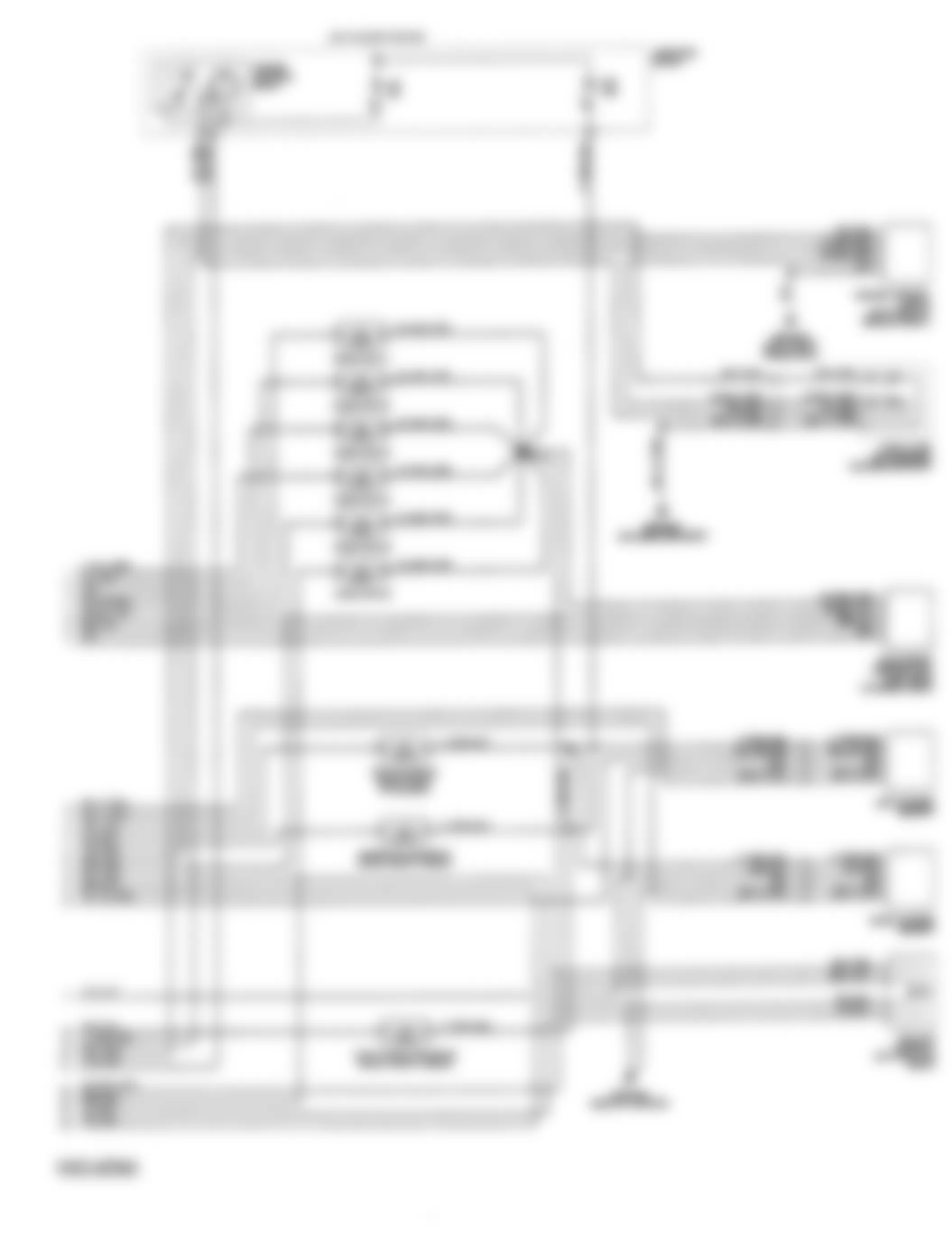
Fig. 32: Chrysler Concorde 1993 - Component Locations - BCM Wiring Diagram - 1 Of 2 (3.5L)
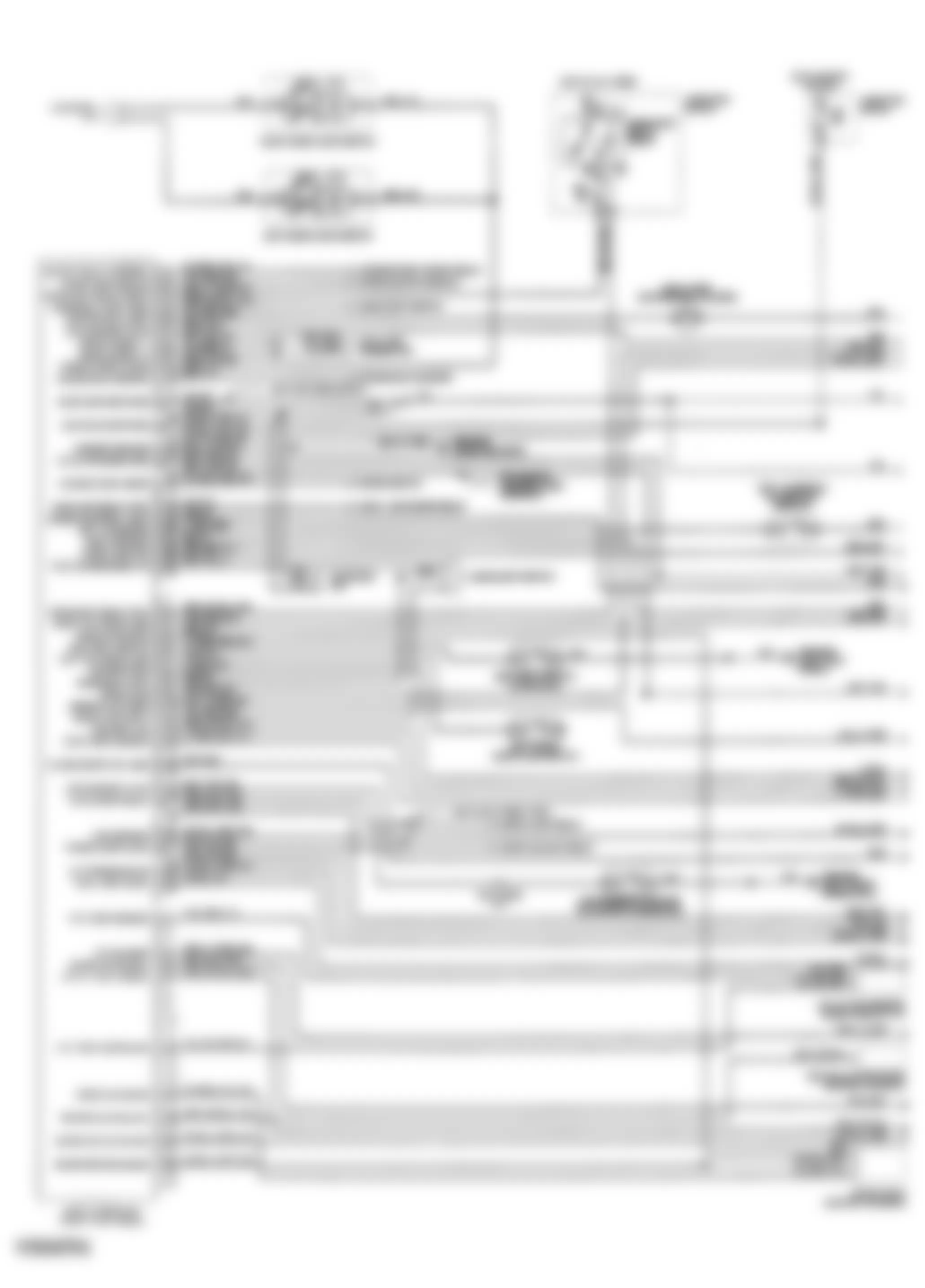
Fig. 33: Chrysler Concorde 1993 - Component Locations - BCM Wiring Diagram - 2 Of 2 (3.5L)