COMPUTER DATA LINES
Computer Data Lines Wiring Diagram for Acura 3.5RL 2004
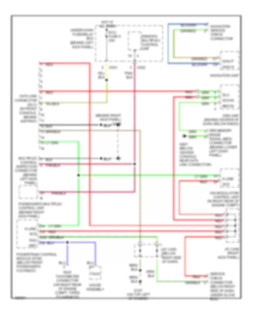
List of elements for Computer Data Lines Wiring Diagram for Acura 3.5RL 2004:
- (behind right kick panel) g402
- (below right side of dash, under glove box)
- C5 scs
- C501
- C502
- Check connector
- Console, behind ashtray)
- D22
- Data link connector (dlc) (in front
- Diag n
- Diag p
- Dlc
- Driver's multiplex control unit
- Ecu fuse 6 20a
- Erase signal (mes) connector (behind lower left dash panel)
- G101 (on top left of engine)
- G801 (below center console, near data link connector)
- Gauge assembly
- Hot at all times
- J/c c448 (right kick panel)
- J/c c456 (below right side of dash)
- K-line
- Mes in
- Multiplex control inspection connector (behind left kick panel)
- Navigation service
- Navigation unit
- Nep
- Passenger's multiplex control unit (behind right kick panel)
- Powertrain control module (pcm) (below front passenger's footrest)
- Red
- Scs
- Scs in
- Service check connector
- Sg2
- Srs memory
- Srs unit (behind center of dash, below radio)
- Tach
- Test tachometer connector (on right rear of engine compt, taped to harness)
- Under-dash fuse/relay box (behind left kick panel)
- Vsa modulator/ control unit (in right rear of engine compt)
 Русский