COMPUTER DATA LINES
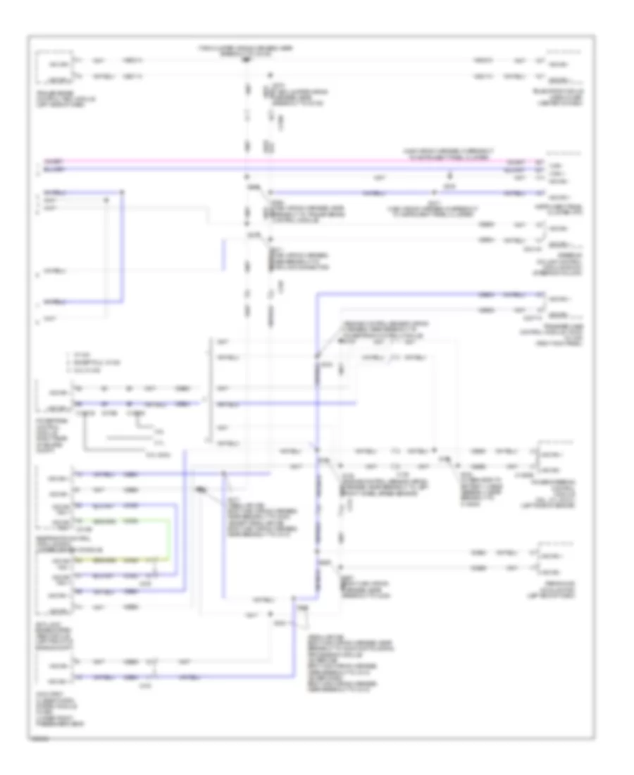
Computer Data Lines Wiring Diagram (1 of 2) for Ford F-150 XLT 2013

List of elements for Computer Data Lines Wiring Diagram (1 of 2) for Ford F-150 XLT 2013:
- (body main wiring harness, near breakout to c311)
- (body main wiring harness, near breakout to g201)
- (engine control sensor wiring harness, near breakout to c214) (w/sync) s246
- (except super cab: body main wiring harness, near breakout to c312) (super cab: body main wiring harness, near breakout to c313)
- (main wiring harness) s261
- (main wiring harness) s262
- (main wiring harness, in breakout to hazard/pad/ traction switch) s235
- (main wiring harness, near breakout to c213) s219
- (main wiring harness, near breakout to mode select switch)
- (main wiring harness, near breakout to mode select switch) s232
- (main wiring harness, near breakout to passenger air bag module) s239
- (or vdb13)
- (or vdb14)
- (super cab: body main wiring harness, near breakout to c313) vdb14
- (w/ adjustable pedals) s212
- (w/ sony radio)
- Accessory protocol interface module (apim) (w/ sync) (center of dash)
- Audio control module (acm) (center of dash)
- Audio digital signal processing (dsp) module (w/ sony radio) (under center console)
- Automatic a/c
- Body control module (bcm) (right kick panel)
- C214
- C2280a
- C2280b
- C2280f
- C228a
- C2395
- C240a
- C248
- C290b
- C294a
- C300
- C312
- C3154a
- C3265c
- C3313b
- C341d
- Data link connector (dlc) (left side of dash)
- Datc hvac module
- Driver seat module (dsm) (w/ memory seats) (under driver's seat)
- Dual climate controlled seat module (dcsm) (w/ climate controlled seats) (under front passenger's seat)
- Emtc hvac module
- Except hmi
- Front controls interface module (fcim) (except hmi)
- Front controls interface module (fcim) (hmi)
- Front display interface module (fdim) (w/o navigation)
- Fuse 15a
- G202 (left side of dash)
- Gd133
- Global positioning system module (gpsm) (w/o navigation) (center of dash)
- Head up display (hud) module (w/ 4 inch display)
- Hot at all times
- Hs can +
- Hs can -
- I can +
- I can -
- Manual a/c
- Ms can +
- Ms can -
- Power running board (prb) module (w/ power running boards) (right rear of cab)
- S213
- S214 (main wiring harness, near breakout to g203)
- S218 (main wiring harness, near breakout to c213)
- S225
- S230 (main wiring harness, in breakout to instrument panel cluster)
- S231
- S233
- S245 (w/sync)
- S249
- S250 (main wiring harness, in breakout to autolamp/sunload sensor)
- S318
- S326
- S328
- S335
- Sbp24
- Tire pressure monitor module (right end of dash)
- Vdb04
- Vdb05
- Vdb06
- Vdb07
- Vdb13
- Vdb14
- W/ 8 inch display
- W/ touch screen 4 inch display
- W/ touch screen 8 inch display
- W/o touch screen & w/ touch screen 8 inch display
Computer Data Lines Wiring Diagram (2 of 2) for Ford F-150 XLT 2013
List of elements for Computer Data Lines Wiring Diagram (2 of 2) for Ford F-150 XLT 2013:
- (engine control sensor wiring harness, near breakout to powertrain control module) s102
- (main wiring harness, in breakout to instrument panel cluster)
- (regular cab: body main wiring harness, near breakout to audio digital signal processing module) (super cab: body main wiring harness, near breakout to c313) (super crew: body main wiring harness, near breakout to c312)
- (t-box jumper wiring harness, near breakout to c2108) s271
- 3.5l
- 3.7l
- 5.0l & 6.2l
- 6.2l w/ 4x2
- Anti-lock brake system (abs) module (left front of engine compt)
- Breakout to trailer brake control module)
- C1381b
- C139
- C1463b
- C1551b
- C175b
- C2108
- C212
- C215
- C2371a
- C2414a
- C248
- C310b
- C312
- Except 6.2l w/ 4x2
- Hs can +
- Hs can -
- Hs can yaw +
- Hs can yaw -
- Hsc1-a
- Hsc1-c
- Hsc2-a
- Hsc2-c
- I can +
- I can -
- Instrument panel cluster (ipc)
- Occupant classification system module (ocsm) (under front passenger's seat)
- Parking aid module (pam) (left end of dash)
- Power steering control module (3.5l, 3.7l & 5.0l) (left side of engine)
- Powertrain control module (right rear of engine compt)
- Restraints control module (rcm) (under center console)
- S100
- S130 (engine control sensor wiring harness, near breakout to left front wheel speed sensor)
- S131
- S152
- S153 (alternator to battery + cable assembly, near breakout to c1463a)
- S204
- S210
- S211 (main wiring harness, near breakout to data link connector)
- S216
- S217 (main wiring harness, in breakout to instrument panel cluster)
- S263
- S317 (regular cab: body main wiring harness, near breakout to g300) (except regular cab: body main wiring harness, near breakout to c313)
- S320
- S323
- S340
- Steering column control module (sccm) (steering column)
- Telematics module (crew chief) (center of dash)
- Trailer brake control (tbc) module (left side of dash)
- Transfer case control module (tccm) (w/ 4x4) (right kick panel)
- Vca23
- Vca24
- Vdb04
- Vdb05
- W/ 4x4