COMPUTER DATA LINES
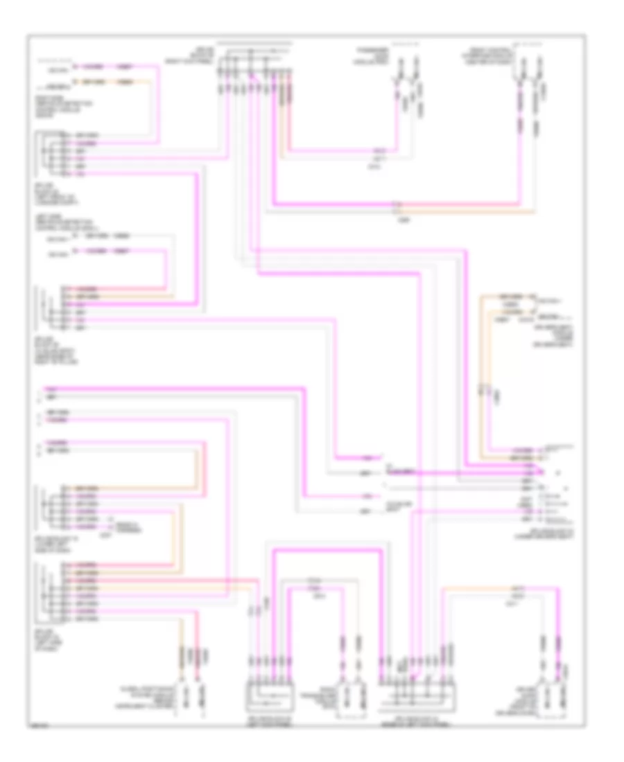
Computer Data Lines Wiring Diagram, Except Hybrid (1 of 3) for Ford Fusion S 2013

List of elements for Computer Data Lines Wiring Diagram, Except Hybrid (1 of 3) for Ford Fusion S 2013:
- (engine controls sensor harness, near breakout to coil on plug 3) s124
- (engine controls sensor harness, near breakout to g103) (w/ auto-start- stop system) s127
- (engine controls sensor harness, near breakout to g103) (w/ auto-start- stop system) s129
- (in steering wheel) g200
- (left end of dash) gateway module
- (lower center of dash) accessory protocol interface module (apim)
- 1.6l
- 2.0l
- 2.5l
- Body control module (bcm) (left end of dash)
- C1232b
- C1381b
- C1551b
- C215
- C2280b
- C2280h
- C238
- C3133
- C900
- Data link connector (dlc)
- Dc to dc converter control module (w/ auto start- stop system) (right rear of engine compt)
- Fuse 10a
- Fuse 7.5a
- G201 (left center of dash)
- Gd214
- Gd215
- Hot at all times
- Hs1 can +
- Hs1 can -
- Hs2 can +
- Hs2 can -
- Hs2 can - c310b
- Hs3 can +
- Hs3 can -
- Micro
- Ms can +
- Ms can -
- Occupant classification system module (under passenger's seat)
- Power train control module (pcm) (w/ auto start- stop system)
- Powertrain control module (pcm)
- Restraints control module (under center console)
- S206
- Sbp13
- Sbp15
- Splice block 17 (left side of dash)
- Splice block 37 (under passenger's seat)
- Splice block 38 (under passenger's seat)
- Vdb04
- Vdb05
- Vdb06
- Vdb07
- Vdb25
- Vdb26
- Vdb29
- Vdb30
- W/ touch screen display
- W/o touch screen display
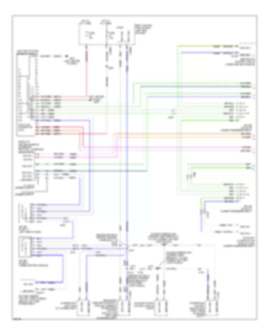
Computer Data Lines Wiring Diagram, Except Hybrid (2 of 3) for Ford Fusion S 2013
List of elements for Computer Data Lines Wiring Diagram, Except Hybrid (2 of 3) for Ford Fusion S 2013:
- (3.7l: battery harness, near breakout to g109)
- (ends in harness)
- (engine controls sensor harness, near breakout to anti-lock brake system module) s118
- (except 3.7l: battery harness, near breakout to c146)
- (not
- (not used)
- Anti-lock brake system (abs) module (left rear of engine compt)
- Audio digital signal processing (dsp) module (right side of luggage compt)
- Audio front control module (right rear of luggage compt)
- C146
- C1463b
- C192
- C215
- C219
- C237
- C238
- C2414a
- C260
- C900
- Evac & fill
- Front control/ display interface module (fcdim) (w/ 4.2 inch display)
- Head up display (hud) module
- Hs2 can +
- Hs2 can + c4326c
- Hs2 can -
- Hs2 can - steering column control module (on steering column)
- Hs3 can +
- Hs3 can + c240a
- Hs3 can -
- Instrument panel cluster (ipc) module
- Power steering control module (right rear of engine compt)
- Proximity warning radar unit (left front of engine compt)
- Rearview camera display module (top center of windshield)
- S107 (engine controls sensor harness, near breakout to c134)
- S108 (engine controls sensor harness, near breakout to c134)
- S115
- S116
- S117 (engine controls sensor harness, near breakout to c192)
- S137 (battery harness, near breakout to c146)
- S138
- Splice block 18 (left side of dash)
- Splice block 20 (center of dash)
- Splice block 21 (center of dash)
- Splice block 39 (near base of right "b" pillar)
- Splice block 59 (top of right "a" pillar)
- Splice block 8 (w/ 4.2 inch display)
- Used)
- Vdb25
- Vdb26
- Vdb29
- Vdb30
- W/ head up display
- W/ sony audio
- W/o head up display
- W/o sony audio
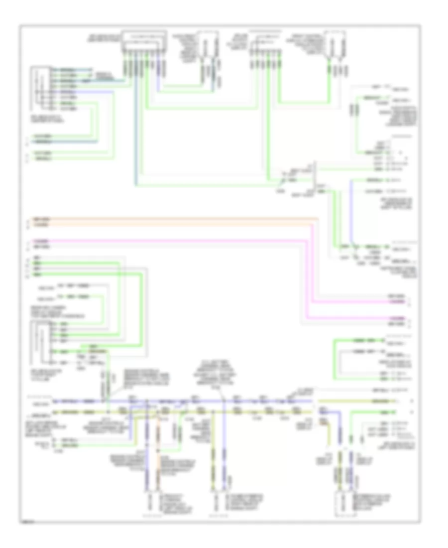
Computer Data Lines Wiring Diagram, Except Hybrid (3 of 3) for Ford Fusion S 2013
List of elements for Computer Data Lines Wiring Diagram, Except Hybrid (3 of 3) for Ford Fusion S 2013:
- (ends in harness)
- (not used)
- C237
- C248
- C260
- C3052
- C311
- C312
- C501a
- C913
- Control module (sod-l)
- Control module (sod-r)
- Driver door module (ddm)
- Driver seat module (dsm) (under driver's seat)
- Front controls interface module (center of dash)
- Global positioning system module (right end of dash)
- Left side obstacle detection
- Ms can +
- Ms can + c2402a
- Ms can + c652a
- Ms can -
- Ms can - c341d
- Passenger door module (pdm)
- Radio transceiver module (right side of luggage compt)
- Right side obstacle detection
- Splice block 15 (lower left side of dash)
- Splice block 16 (left side of dash)
- Splice block 32 (w/ blind spot information system) (left side of luggage compt)
- Splice block 33 (under driver's seat)
- Splice block 34 (base of left kick panel)
- Splice block 35 (left kick panel)
- Splice block 36 (right kick panel)
- Splice block 41 (w/ blind spot information system) (right side of luggage compt)
- Used) (not
- Vdb06
- Vdb07
Computer Data Lines Wiring Diagram, Hybrid (1 of 3) for Ford Fusion S 2013
List of elements for Computer Data Lines Wiring Diagram, Hybrid (1 of 3) for Ford Fusion S 2013:
- (engine controls sensor harness, in breakout to c215) s129
- (engine controls sensor harness, near breakout to battery junction box)
- (front of center console) accessory protocol interface module (apim)
- (left center of dash) g200
- (left end of dash) gateway module
- (power steering hev harness, near breakout to high current battery junction box)
- (power steering hev harness, near breakout to high current battery junction box) s199
- Air conditioning control module (accm)
- Battery energy control module (becm) (behind left side of rear seat)
- Body control module (bcm) (left end of dash)
- C1458a
- C146
- C175b
- C215
- C2280b
- C2280h
- C238
- C3133
- C900
- Charge port light ring (at charge port)
- Data link connector (dlc)
- Fuse 10a
- Fuse 7.5a
- G201 (left center of dash)
- Gd214
- Gd215
- Hot at all times
- Hs1 can +
- Hs1 can + c4237a
- Hs1 can -
- Hs2 can +
- Hs2 can -
- Hs2 can - c310b
- Hs3 can +
- Hs3 can -
- Micro
- Module (ocsm) (under passenger's seat)
- Ms can +
- Ms can -
- Occupant classification
- Powertrain control module (pcm) (right rear of engine compt)
- Restraints control module (under center console)
- S124
- S127
- S198
- S206
- Sbp13
- Sbp15
- Secondary onboard diagnostic module c (sobdmc)/ transmission control module (tcm) (left side of engine compt)
- Splice block 17 (left side of dash)
- Splice block 37 (under passenger's seat)
- Splice block 38 (under passenger's seat)
- Splice block 6 (under center console)
- Vdb04
- Vdb05
- Vdb06
- Vdb07
- Vdb25
- Vdb26
- Vdb29
- Vdb30
- W/ touch screen display
- W/o touch screen display
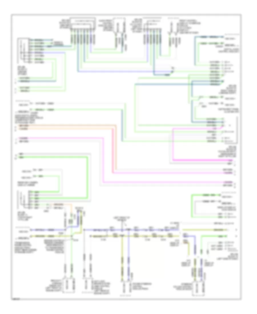
Computer Data Lines Wiring Diagram, Hybrid (2 of 3) for Ford Fusion S 2013
List of elements for Computer Data Lines Wiring Diagram, Hybrid (2 of 3) for Ford Fusion S 2013:
- (engine controls sensor harness, near breakout to transmission range control module)
- (left front of vehicle)
- (not used)
- Anti-lock brake system (abs) control module (left rear of engine compt)
- Audio digital signal processing (dsp) module (under right side of package tray)
- Audio front control module (acm) (center of dash)
- C146
- C1463b
- C192
- C215
- C219
- C237
- C238
- C2414a
- C260
- C900
- Digital audio control module c
- Ends in harness
- Evac & fill
- Front control/ display interface module (w/ 4.2 inch display) (center of dash) hs3 can -
- Head up display (hud) module
- Hs2 can +
- Hs2 can + c4326c
- Hs2 can -
- Hs3 can +
- Hs3 can + c240a
- Hs3 can -
- Hs3 can - c4820a
- Instrument panel cluster (ipc)
- Power steering control module (pscm)
- Proximity warning radar unit (left front of engine compt)
- Rearview camera display mirror
- S128
- S130
- S137
- S138
- Splice block 14 (top of right "a" pillar)
- Splice block 18 (left side of dash)
- Splice block 20 (center of dash)
- Splice block 21 (center of dash)
- Splice block 22 (w/ 4.2 inch display) (left side of dash)
- Splice block 39 (w/o blind spot) (near base of right "b" pillar)
- Splice block 40 (right side of luggage compt)
- Steering column control module (sccm)
- Transmission range control module (trcm) (right rear corner of engine compt)
- Vdb25
- Vdb26
- Vdb29
- Vdb30
- W/ head up display
- W/o head up display
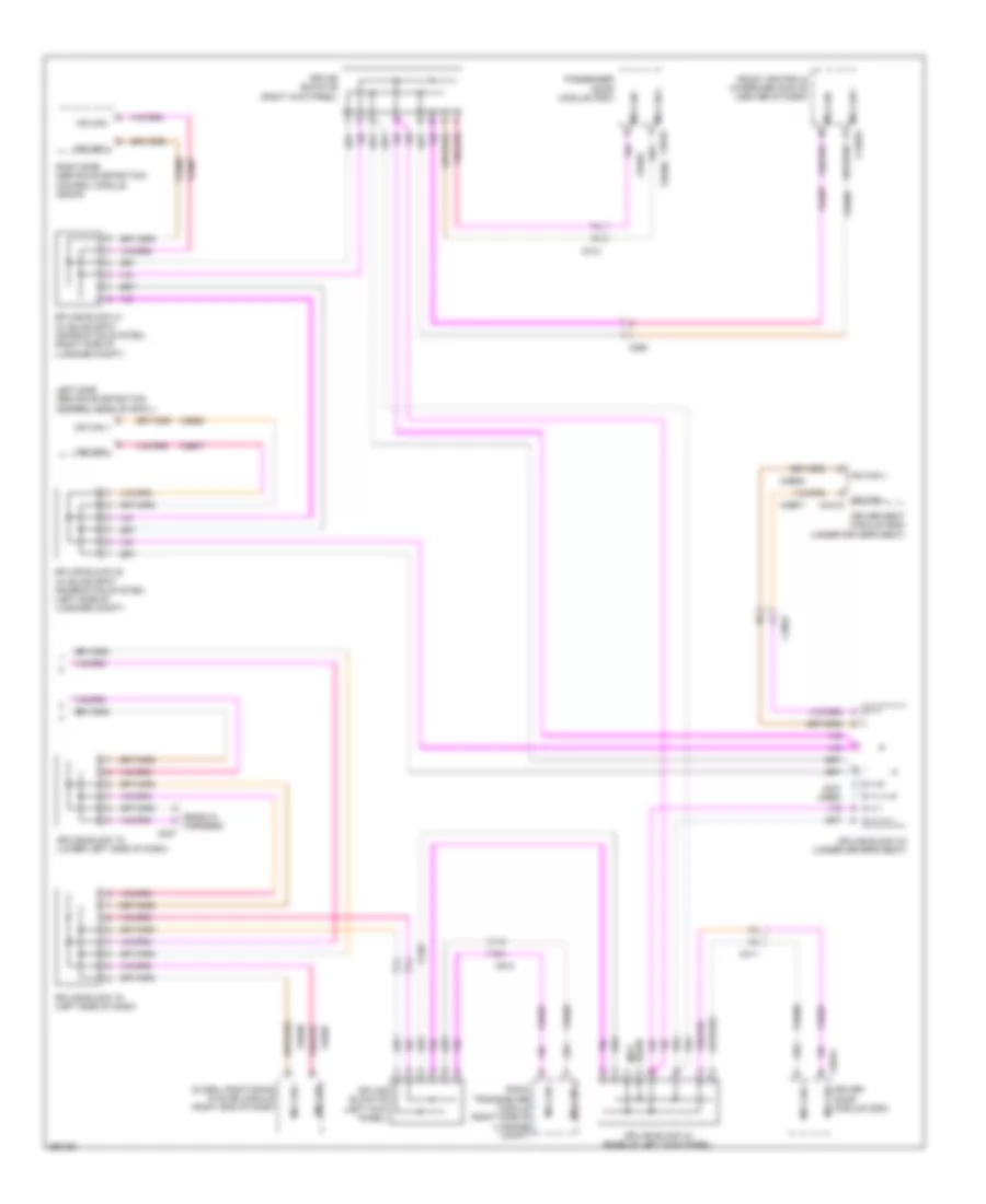
Computer Data Lines Wiring Diagram, Hybrid (3 of 3) for Ford Fusion S 2013
List of elements for Computer Data Lines Wiring Diagram, Hybrid (3 of 3) for Ford Fusion S 2013:
- (ends in harness)
- (not used)
- C237
- C248
- C260
- C3052
- C311
- C312
- C501a
- C913
- Control module (sod-l)
- Control module (sod-r)
- Driver door module (front of driver's door)
- Driver's seat module (under driver's seat)
- Front control interface module (center of dash)
- Global positioning system module (behind instrument cluster)
- Left side obstacle detection
- Ms can +
- Ms can + c2402a
- Ms can + c652a
- Ms can -
- Ms can - c341d
- Passenger door module (pdm)
- Radio transceiver module (rtm)
- Right side obstacle detection
- Splice block 15 (lower left side of dash)
- Splice block 16 (left side of dash)
- Splice block 32 (left front of luggage compt)
- Splice block 33 (under driver's seat)
- Splice block 34 (base of left kick panel)
- Splice block 35 (left kick panel)
- Splice block 36 (right kick panel)
- Splice block 39 (w/ blind spot) (near base of right "b" pillar)
- Used) (not
- Vdb06
- Vdb07
- W/ blind spot
- W/o blind spot