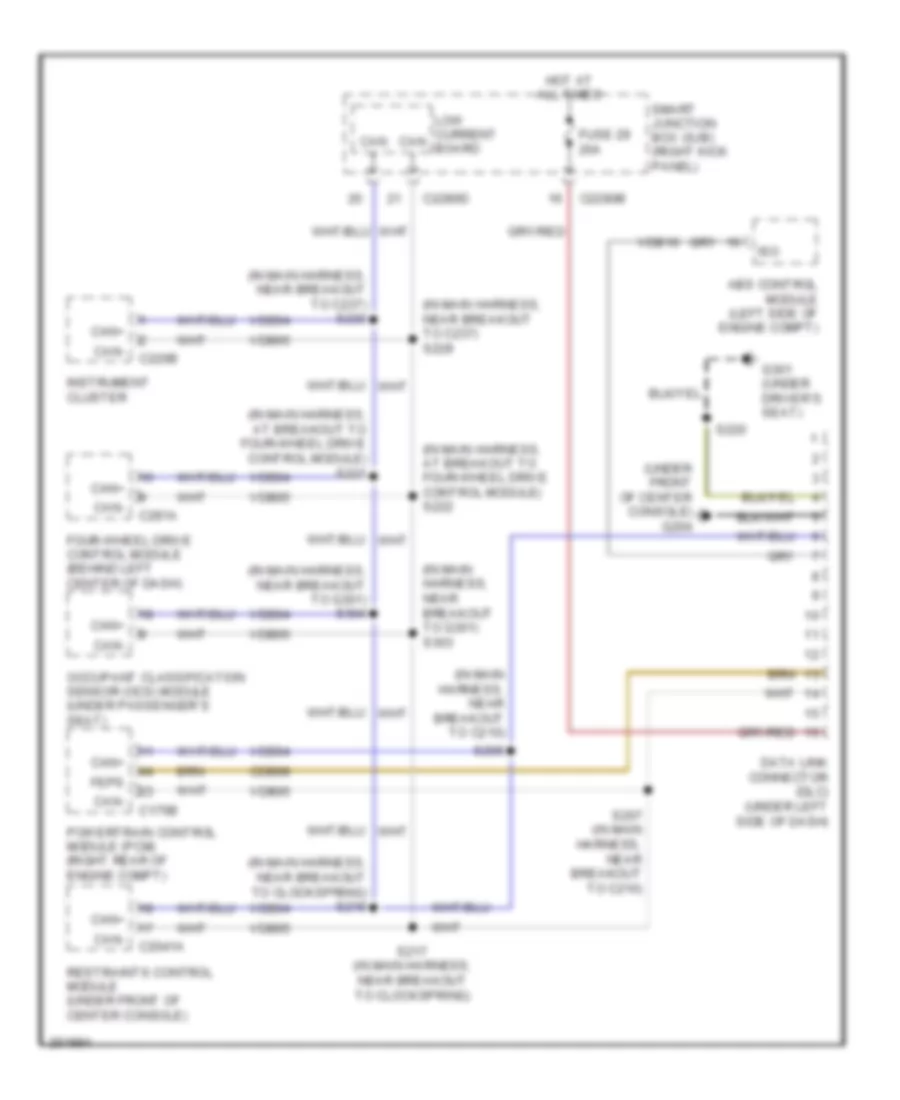
COMPUTER DATA LINES
Computer Data Lines Wiring Diagram for Ford Ranger 2007
List of elements for Computer Data Lines Wiring Diagram for Ford Ranger 2007:
- (in main harness, at breakout to four-wheel drive control module) s221
- (in main harness, at breakout to four-wheel drive control module) s222
- (in main harness, near breakout to c210)
- (in main harness, near breakout to c237) s229
- (in main harness, near breakout to c237) s230
- (in main harness, near breakout to clockspring) s218
- (in main harness, near breakout to g301) s303
- (in main harness, near breakout to g301) s304
- (under front of center console) g204
- Abs control module (left side of engine compt)
- C175b
- C2041a
- C220b
- C2280b
- C2280d
- C281a
- Can +
- Can -
- Can+
- Can-
- Cdb08
- Data link connector (dlc) (under left side of dash)
- Feps
- Four-wheel drive control module (behind left center of dash)
- Fuse 29 20a
- G301 (under driver`s seat)
- Hot at all times
- Instrument cluster
- Iso
- Low current board
- Occupant classification sensor (ocs) module (under passenger`s seat)
- Powertrain control module (pcm) (right rear of engine compt)
- Restraints control module (under front of center console)
- S206
- S207 (in main harness, near breakout to c210)
- S217 (in main harness, near breakout to clockspring)
- S220
- Smart junction box (sjb) (right kick panel)
- Vdb04
- Vdb05
- Vdb10
 Русский