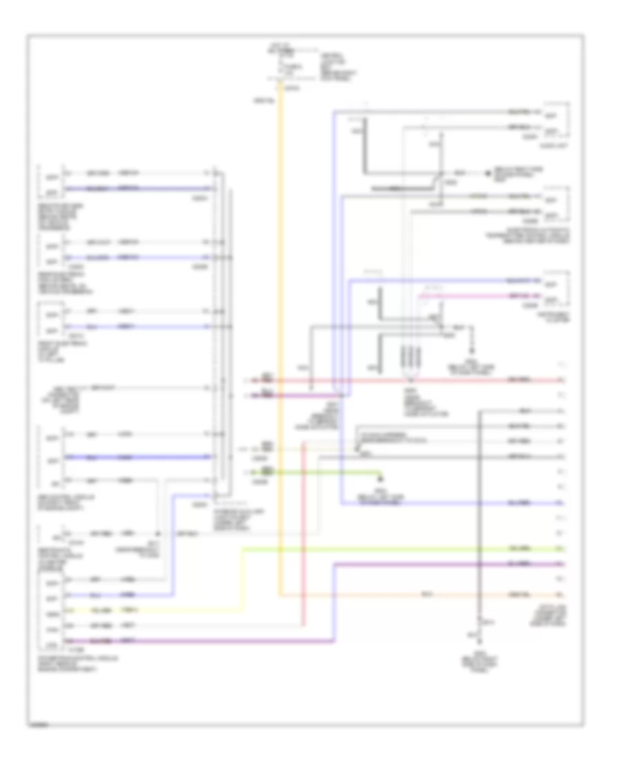
COMPUTER DATA LINES
Computer Data Lines Wiring Diagram for Ford Thunderbird 2005
List of elements for Computer Data Lines Wiring Diagram for Ford Thunderbird 2005:
- (below right side of dash panel) g203
- (in main harness, near breakout to c213)
- (near breakout to c248)
- (near breakout to defrost mode actuator)
- 4-cf6
- 4-ec7
- 4-ee1
- 4-ee6
- 4-eg11
- 4-eg12a
- 4-eg13a
- 4-fa10
- 4-re8
- 5-cf6
- 5-ec7
- 5-eg11
- 5-eg12a
- 5-eg13a
- 5-fa10
- 5-re8
- 7-re14
- Abs control module (on right front of engine compt)
- Abs test connector (on left rear of engine compt)
- Audio unit
- C175b
- C201c
- C220b
- C228b
- C240c
- C270a
- C283a
- C283b
- C283c
- C283d
- C310a
- C420c
- Can+
- Can-
- Central junction box (behind right kick panel)
- Data link connector (under left side of dash)
- Electronic automatic temperature control module (behind center of dash)
- Feps
- Front electronic module (in left "a" pillar)
- Fuse 6 10a
- G203 (below right side of dash panel)
- G204 (below left side of dash panel)
- Hot at all times
- Instrument cluster
- Interior auxiliary junction box (under left side of dash)
- Iso
- Nca
- Powertrain control module (right rear of engine compartment)
- Rear electronic module (rem) (behind seats, on vehicle crossbeam)
- Remote keyless entry module (behind seats, on vehicle crossbeam)
- Restraints control module (in center console)
- S201
- S205
- S206
- S207 (near breakout to defrost mode actuator)
- S214
- S217
- S222
- Scp+
- Scp-
 Русский