COMPUTER DATA LINES
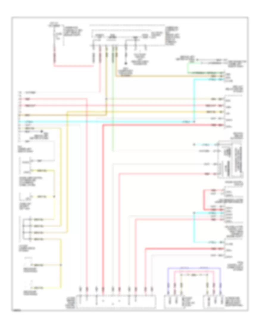
Computer Data Lines Wiring Diagram for Honda Element LX 2008
List of elements for Computer Data Lines Wiring Diagram for Honda Element LX 2008:
- (behind left center of dash) g451
- +b back up
- 5v stabilize circuit/ controller area network controller
- A10
- A24
- Audio unit (usa: ex & sc)
- B10
- B19
- Bus (+)
- Bus (-)
- Bus gnd
- Bus meter
- Can-h
- Can-l
- Ceiver trans- uart
- D10
- D11
- Diag-h
- Diag-ii
- Dlc (under left side of dash)
- E11
- E12
- E24
- E29
- E30
- Ecm/pcm (behind glove box)
- Fuse 10a
- G401 (under right middle side of dash)
- G451 (behind left center of dash)
- Gauge control module
- Gnd
- Hot at all times
- Immobilizer control unit-receiver (in steering wheel cover)
- Imoes unit (except 2007 usa)
- J/c c406 (behind gauge control module)
- J/c c457 (under middle of dash)
- K-line
- K10
- Lg1
- Lg3
- Logic
- Mes
- Mes connector (under left side of dash)
- Mpcs chk
- Multiplex control unit
- Multiplex control unit service check connector
- Pnk
- Red
- Scs
- Secondary ho2s shield
- Srs unit (below center of dash)
- Tpms control unit (under middle of dash)
- Transceiver f-can
- Underdash fuse/relay box (behind left side of dash, right of steering column)
- Underhood fuse/relay box (left rear of engine compt)
- Vsa modulator- control unit (right rear corner of engine compt)
- Vsa sensor cluster (under center console)
- Wen
- Xm receiver (usa: ex & sc) (behind right quarterpanel)
 English