COMPUTER DATA LINES
Data Link Connector Wiring Diagram for Honda Odyssey Touring 2013

List of elements for Data Link Connector Wiring Diagram for Honda Odyssey Touring 2013:
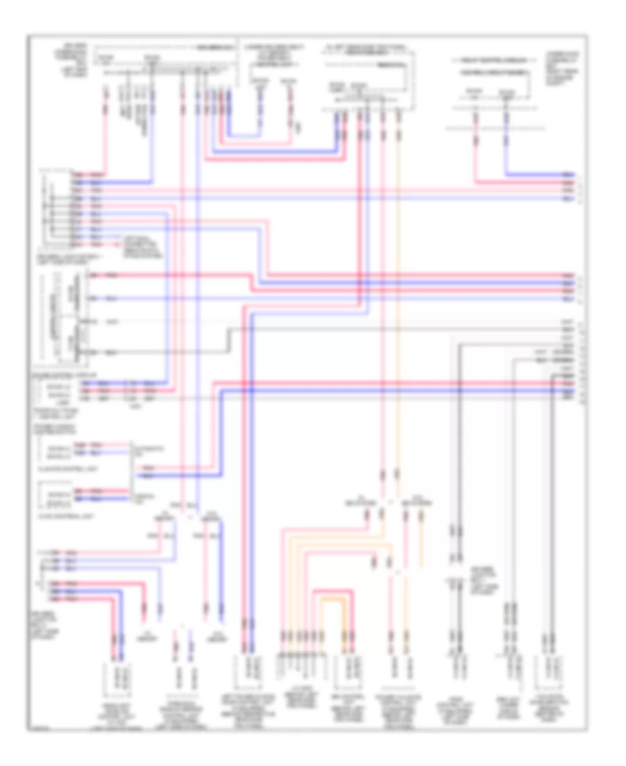
F-CAN & B-CAN Wiring Diagram (1 of 2) for Honda Odyssey Touring 2013
List of elements for F-CAN & B-CAN Wiring Diagram (1 of 2) for Honda Odyssey Touring 2013:
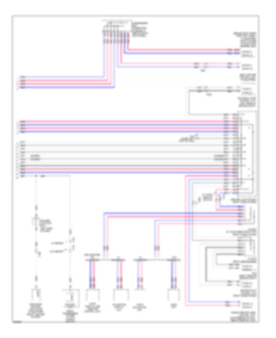
F-CAN & B-CAN Wiring Diagram (2 of 2) for Honda Odyssey Touring 2013
List of elements for F-CAN & B-CAN Wiring Diagram (2 of 2) for Honda Odyssey Touring 2013:
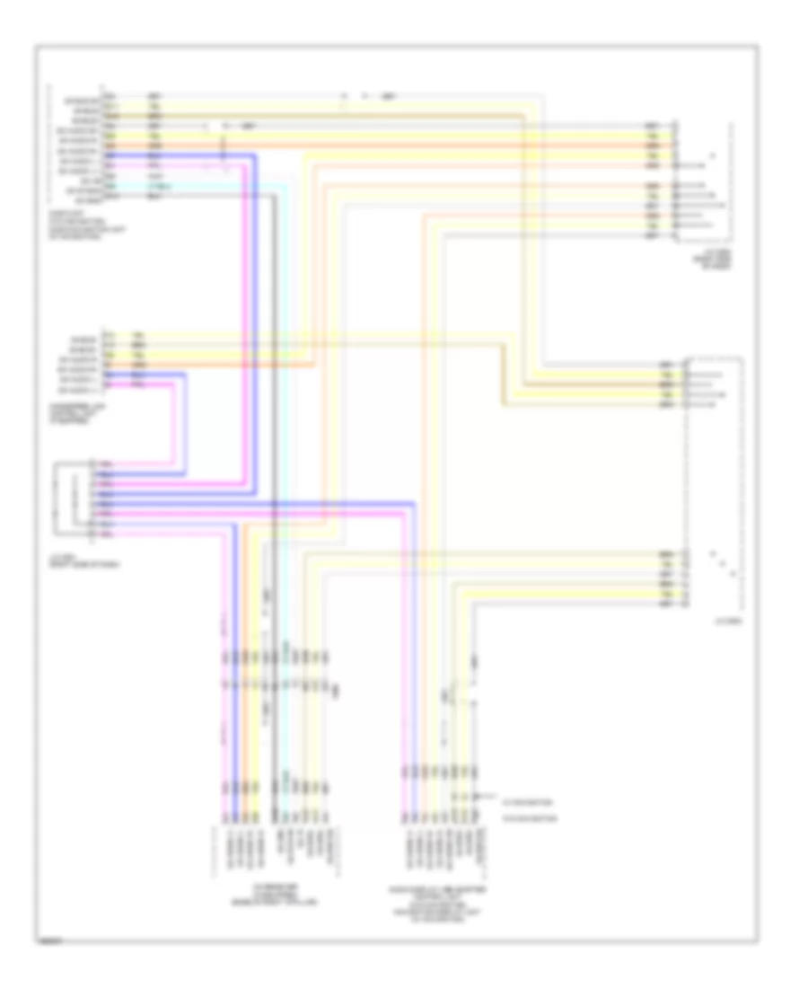
GA-NET Bus/GA-NET Audio Wiring Diagram for Honda Odyssey Touring 2013
List of elements for GA-NET Bus/GA-NET Audio Wiring Diagram for Honda Odyssey Touring 2013: