COMPUTER DATA LINES
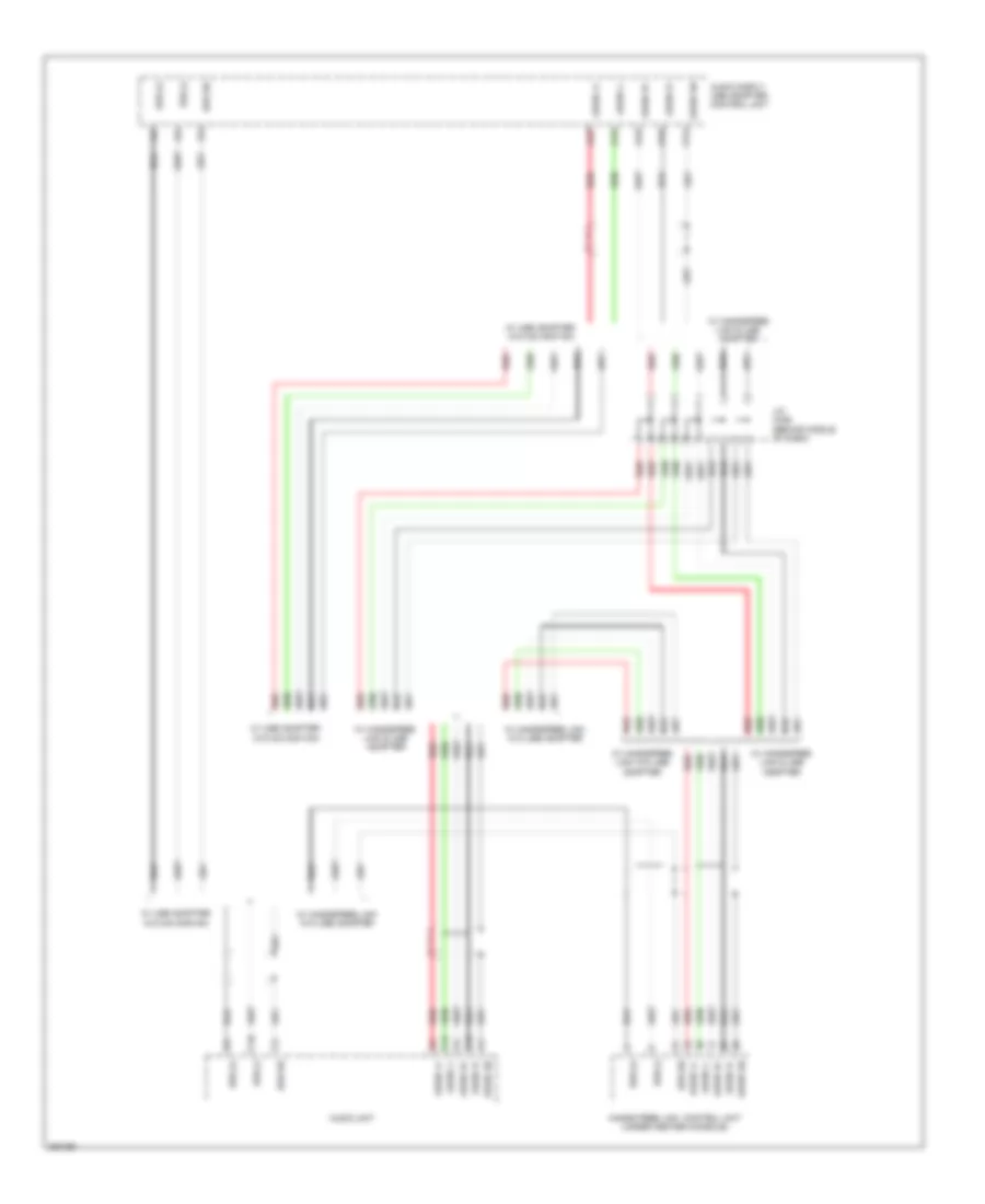
B-CAN Wiring Diagram/UART Communication Line for Honda Pilot LX 2012

List of elements for B-CAN Wiring Diagram/UART Communication Line for Honda Pilot LX 2012:
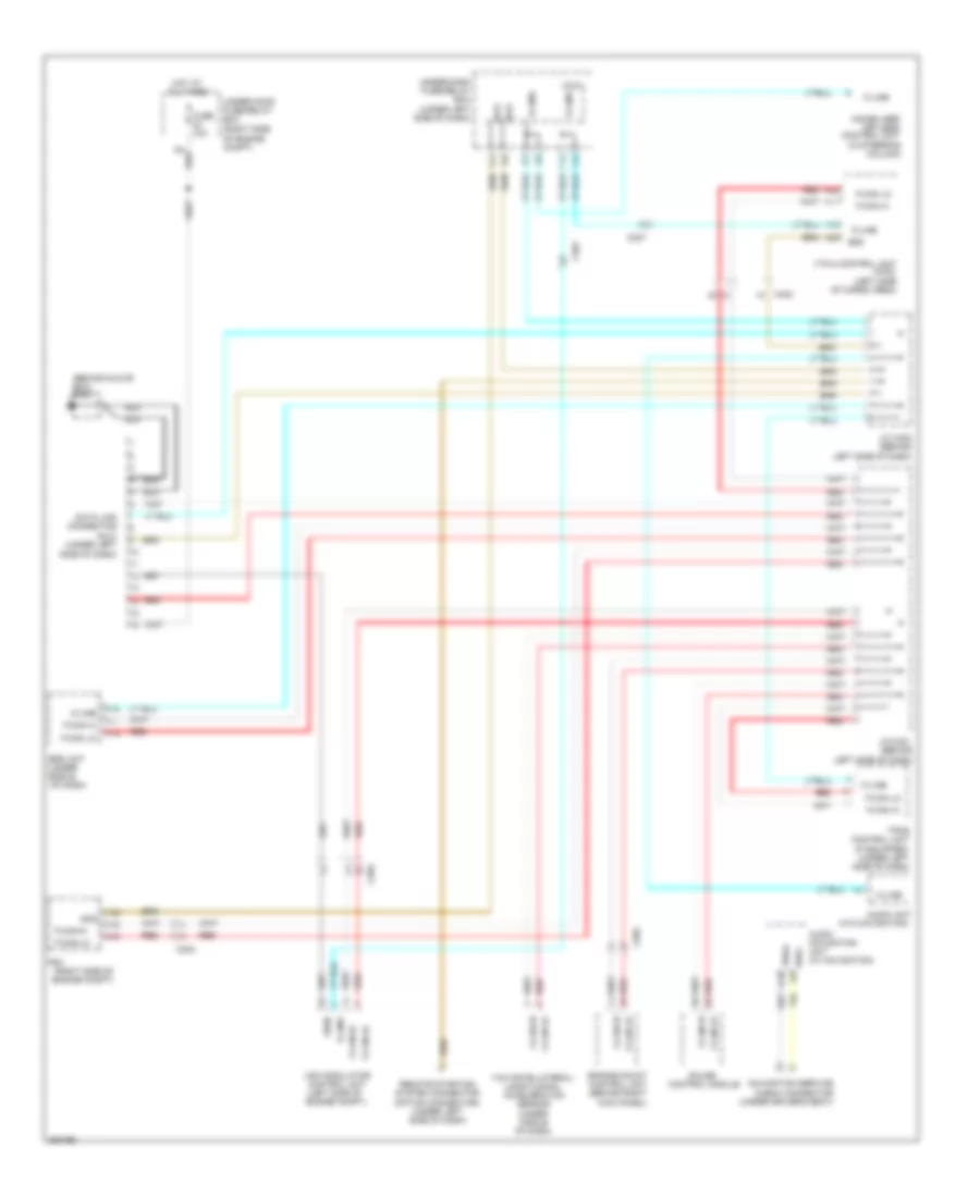
Data Link Connector Wiring Diagram for Honda Pilot LX 2012
List of elements for Data Link Connector Wiring Diagram for Honda Pilot LX 2012:
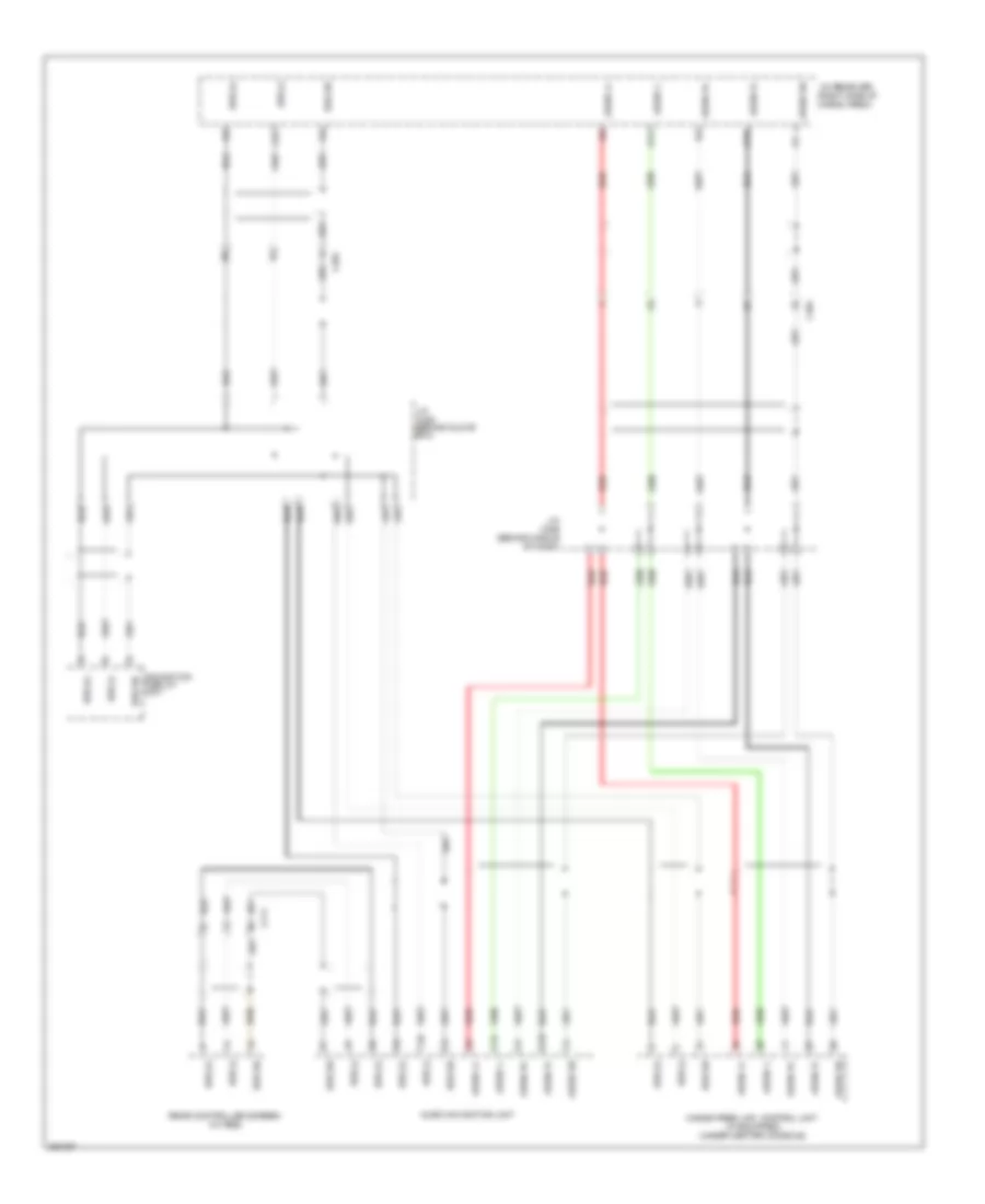
GA-NET Bus/GA-NET Audio Wiring Diagram, with Navigation for Honda Pilot LX 2012
List of elements for GA-NET Bus/GA-NET Audio Wiring Diagram, with Navigation for Honda Pilot LX 2012:
GA-NET Bus/GA-NET Audio Wiring Diagram, without Navigation with XM Radio for Honda Pilot LX 2012
List of elements for GA-NET Bus/GA-NET Audio Wiring Diagram, without Navigation with XM Radio for Honda Pilot LX 2012:
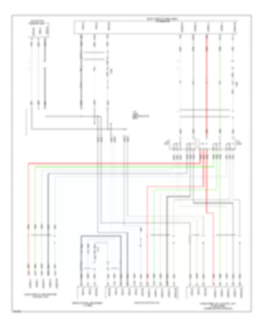
GA-NET Bus/GA-NET Audio Wiring Diagram, without Navigation without XM Radio for Honda Pilot LX 2012
List of elements for GA-NET Bus/GA-NET Audio Wiring Diagram, without Navigation without XM Radio for Honda Pilot LX 2012: