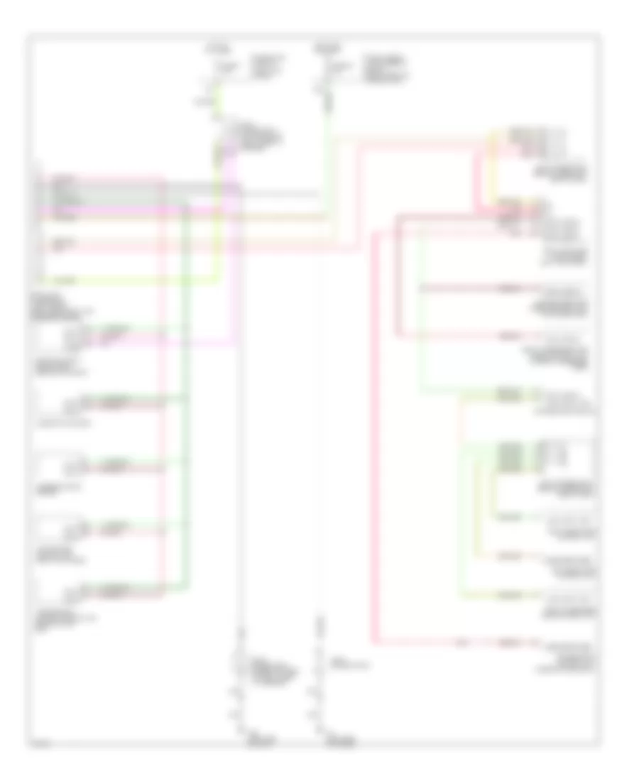
COMPUTER DATA LINES
Computer Data Lines for Infiniti Q45 2002
List of elements for Computer Data Lines for Infiniti Q45 2002:
- (left kick panel)
- Body computer module (bcm) (left kick panel)
- Can h
- Can l
- Combination meter
- Data line a1
- Data line a2
- Data line a3
- Data link connector (left side of dash, near hood lock release handle)
- Drivers door module
- Drivers seat control unit (under drivers seat)
- Drivers side door mirror control unit (in drivers door)
- Engine control module (ecm) (behind glove box)
- F8 (left side of engine)
- Front passenger door control unit
- Front passenger door mirror control unit (in front passenger door)
- Fuse 58 10a
- Fuse 6 10a
- Fuse block (j/b) no. 1
- Fuse, fusible link and relay block (right front of engine compt)
- Hot at all times
- Hot in on or start
- Joint connector 11 (top center of dash, taped to harness)
- Joint connector 15 (behind upper right side of dash)
- Joint connector 29
- Joint connector 5 (upper left side of dash, taped to harness)
- Joint connector 8 (behind upper left side of dash)
- Kline
- Left rear door control unit
- Local data line
- M25 (left side of dash)
- Pnk
- Right rear door control unit
- Steering angle sensor
- Transmission control module (tcm) (behind glove box)
- Vdc/tcs/abs control unit (right kick panel)
 English