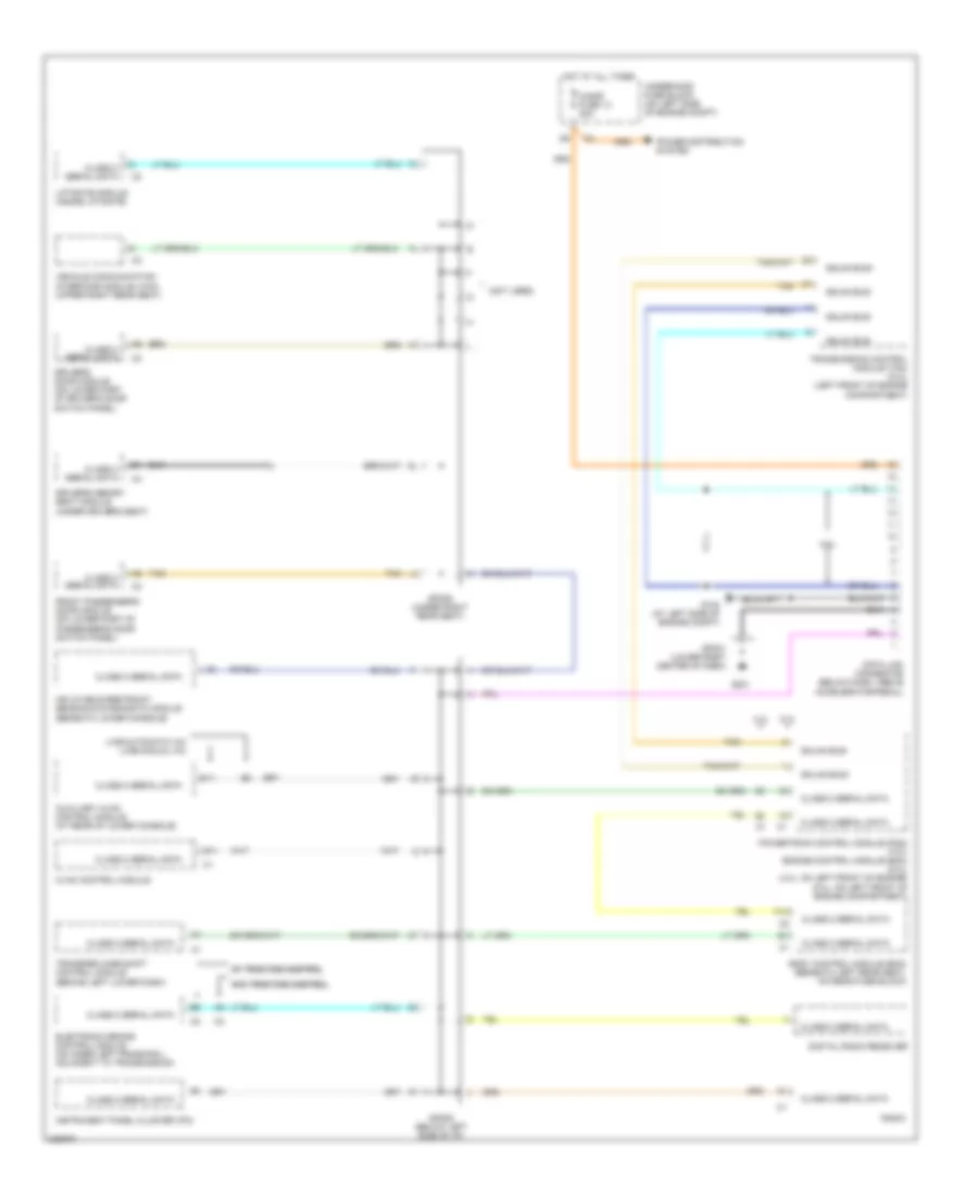
COMPUTER DATA LINES
Computer Data Lines Wiring Diagram for Isuzu Ascender LS 2005
List of elements for Computer Data Lines Wiring Diagram for Isuzu Ascender LS 2005:
- class 2 serial data
- (not used)
- 4.2l
- 5.3l
- A11
- Auxiliary hvac control module (at rear of lower console)
- B11
- Body control module (bcm) (beneath left rear seat, on rear fuse block)
- Cigar fuse 13 20a
- Class 2 serial data
- Data link connector (below dash, above accelerator pedal)
- Digital radio receiver
- Driver's door module (on lower part of driver's door switch panel)
- Driver's memory seat module (under driver's seat)
- Electronic brake control module (on inner left frame rail, adjacent to transmission)
- F14
- Front passenger's door module (on lower part of passenger's door switch panel)
- G102 (at left side of engine compt)
- G201
- Gmlan bus+
- Gmlan bus-
- Hot at all times
- Hvac control module
- Inflatable restraint sensing & diagnostic module (beneath lower console)
- Instrument panel cluster (ipc)
- Liftgate module (inside liftgate)
- Lwb-automatic a/c lwb-manual a/c
- Power distribution system
- Powertrain control module (pcm) (4.2l) engine control module (ecm) (5.3l) (4.2l: on left front of engine) (5.3l: on left front of engine compartment)
- Radio
- Sp201 (lower right center of dash)
- Sp205 (below left side of i/p)
- Sp306 (under right rear seat)
- Tan
- Transfer case shift control module (behind left lower dash)
- Transmission control module (tcm) (5.3l) (left front of engine compartment)
- Underhood fuse block (on left side of engine compt)
- Vehicle communication interface module (vcim) (upper right rear seat)
- W/ traction control w/ traction control
- W/o traction control w/o traction control
 English