COMPUTER DATA LINES
2.6L
2.6L, Data Link Connector Wiring Diagram for Isuzu Rodeo LS 1994

List of elements for 2.6L, Data Link Connector Wiring Diagram for Isuzu Rodeo LS 1994:
- "check engine" malfunction indicator lamp (mil)
- (left kick panel)
- (right side of engine)
- Dash fuse box (left i/p)
- Data link connector (left kick panel)
- Diagnostic start/dlc input
- Diagnostic test terminal
- Engine control module (left kick panel)
- Fuse 10a
- G120
- Hot in on or start
- Instrument cluster
- Mil control
3.2L
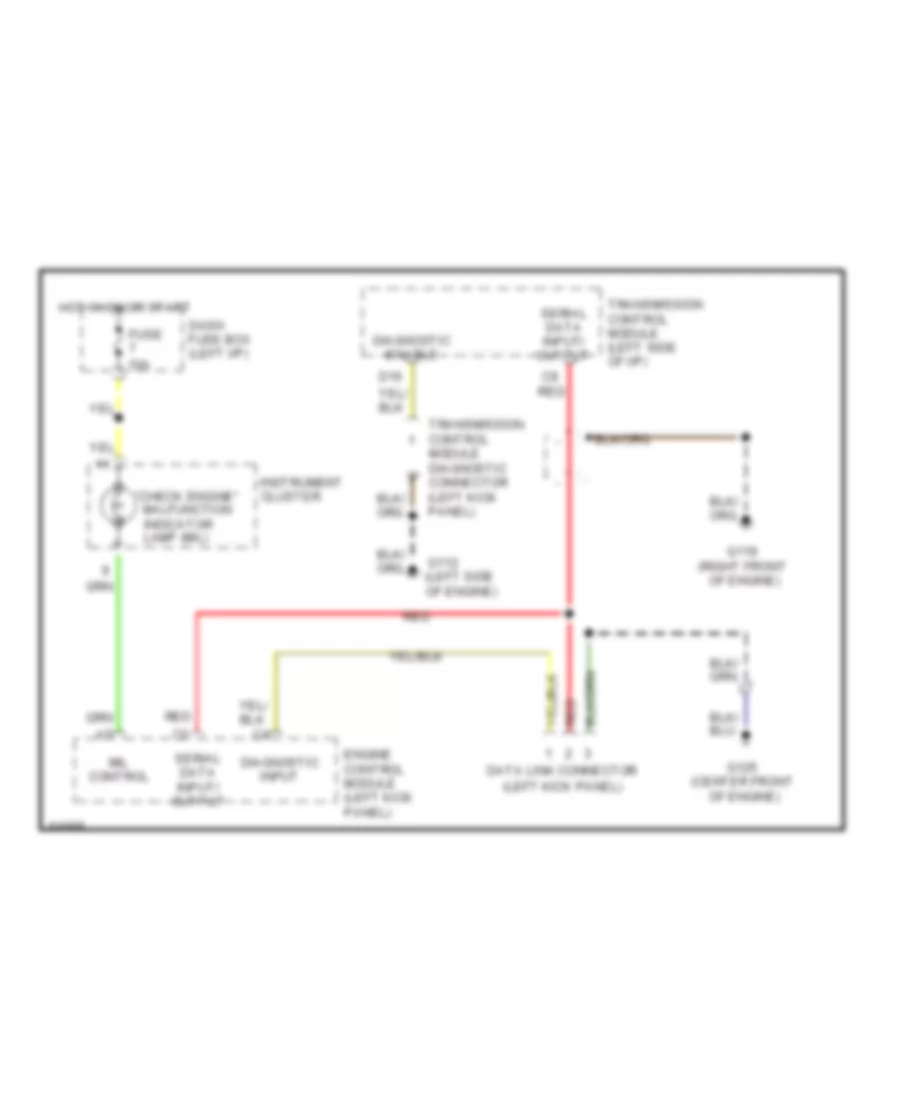
3.2L, Data Link Connector Wiring Diagram for Isuzu Rodeo LS 1994
List of elements for 3.2L, Data Link Connector Wiring Diagram for Isuzu Rodeo LS 1994:
- "check engine" malfunction indicator lamp (mil)
- (center front
- (left kick panel)
- (right front
- C8 red
- D16
- Dash fuse box (left i/p)
- Data link connector
- Diagnostic enable
- Diagnostic input
- Engine control module (left kick panel)
- Fuse 10a
- G112 (left side of engine)
- G119
- G125
- Hot in on or start
- Instrument cluster
- Mil control
- Of engine)
- Red
- Serial data input/ output
- Transmission control module (left side of i/p)
- Transmission control module diagnostic connector (left kick panel)