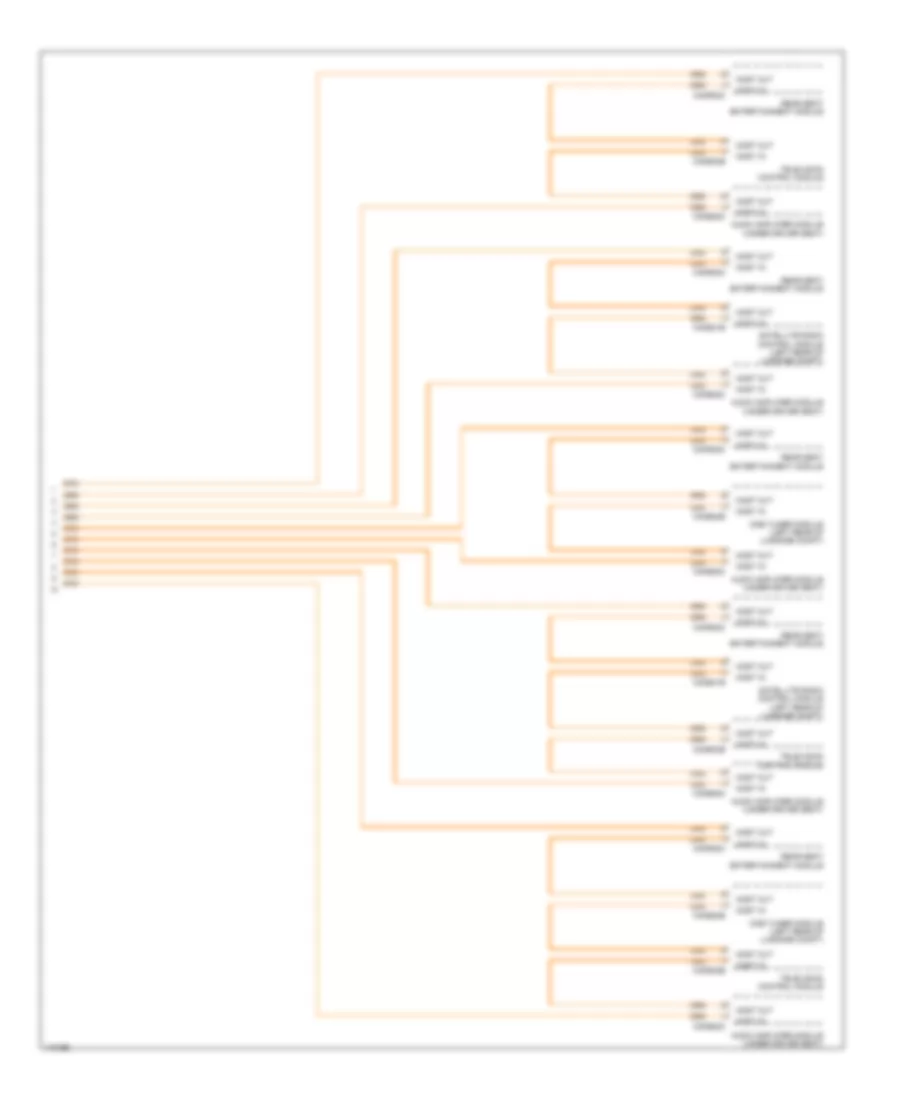
COMPUTER DATA LINES
Diagnostic Socket Wiring Diagram (1 of 5) for Land Rover Range Rover 2014

List of elements for Diagnostic Socket Wiring Diagram (1 of 5) for Land Rover Range Rover 2014:
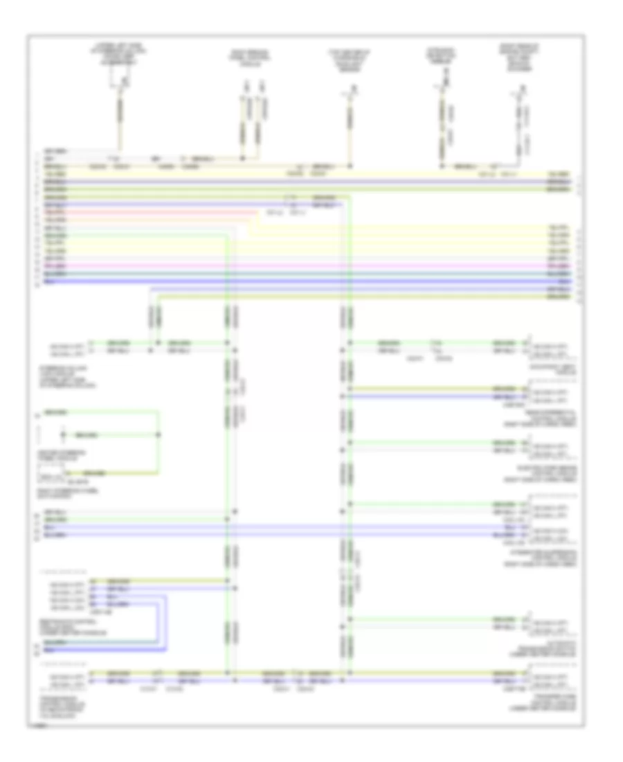
Diagnostic Socket Wiring Diagram (2 of 5) for Land Rover Range Rover 2014
List of elements for Diagnostic Socket Wiring Diagram (2 of 5) for Land Rover Range Rover 2014:
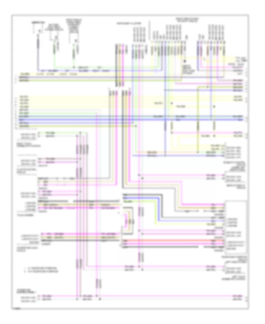
Diagnostic Socket Wiring Diagram (3 of 5) for Land Rover Range Rover 2014
List of elements for Diagnostic Socket Wiring Diagram (3 of 5) for Land Rover Range Rover 2014:
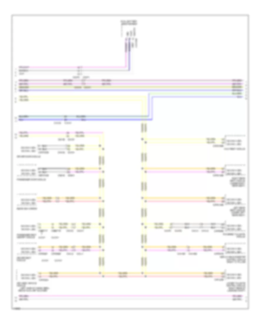
Diagnostic Socket Wiring Diagram (4 of 5) for Land Rover Range Rover 2014
List of elements for Diagnostic Socket Wiring Diagram (4 of 5) for Land Rover Range Rover 2014:
Diagnostic Socket Wiring Diagram (5 of 5) for Land Rover Range Rover 2014
List of elements for Diagnostic Socket Wiring Diagram (5 of 5) for Land Rover Range Rover 2014:
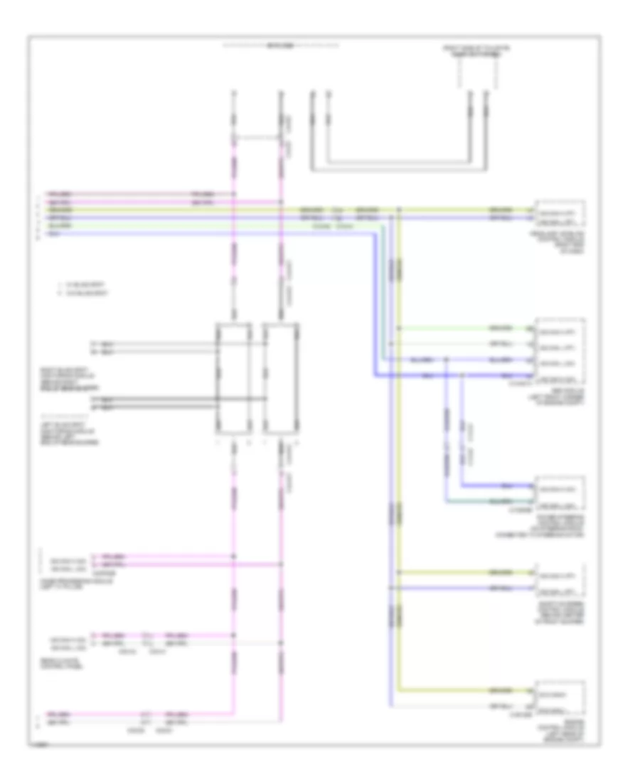
Fibre Optic Network Wiring Diagram (1 of 2) for Land Rover Range Rover 2014
List of elements for Fibre Optic Network Wiring Diagram (1 of 2) for Land Rover Range Rover 2014:
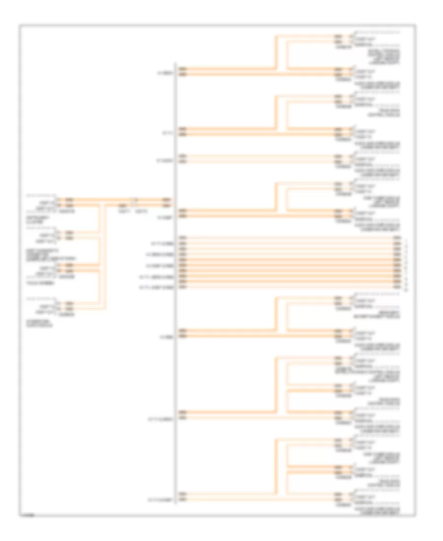
Fibre Optic Network Wiring Diagram (2 of 2) for Land Rover Range Rover 2014
List of elements for Fibre Optic Network Wiring Diagram (2 of 2) for Land Rover Range Rover 2014: