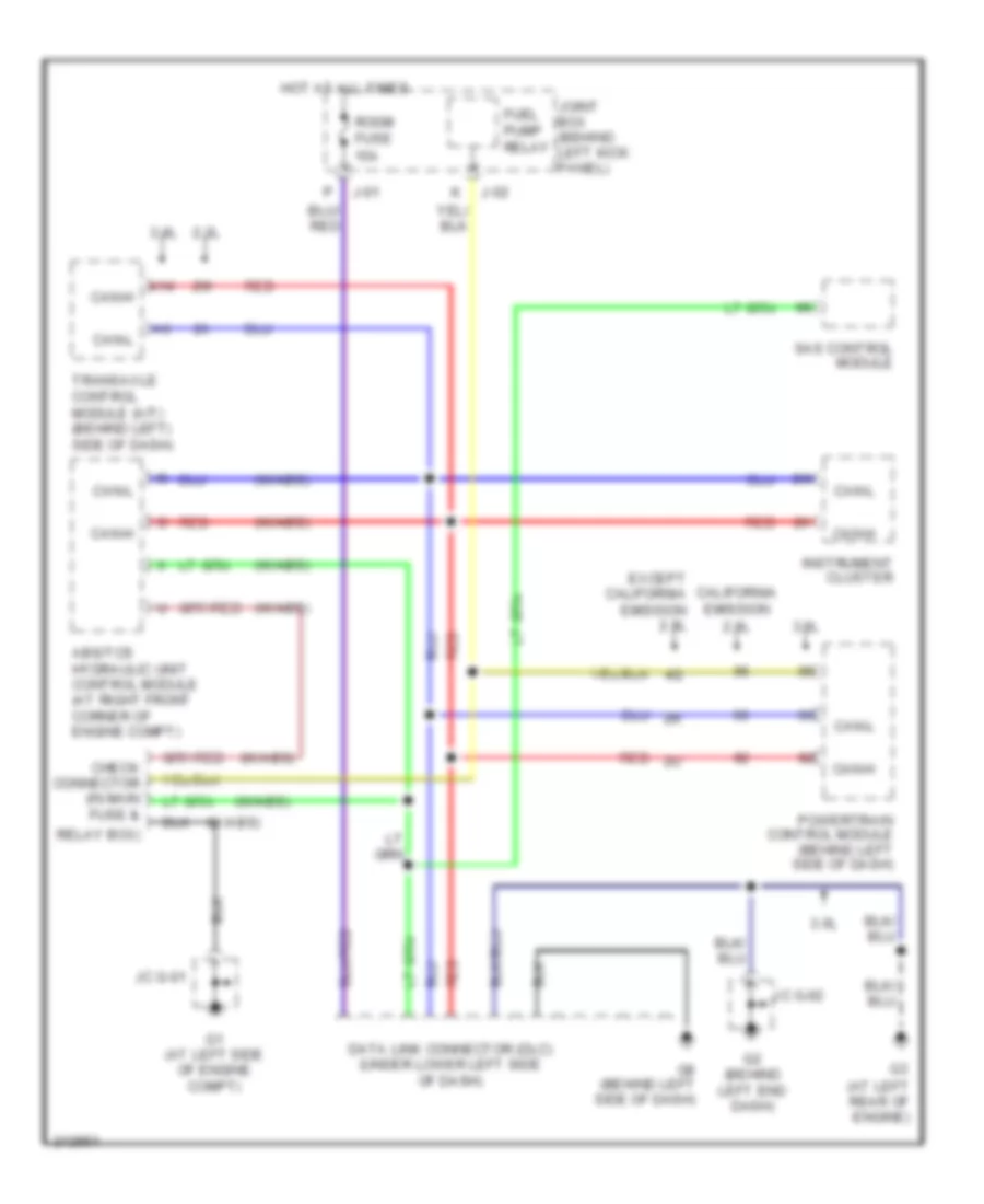
AUTOMOTIVE ELECTRICIANS PORTAL

COMPUTER DATA LINES – Mazda 6 s 2005 – SYSTEM WIRING DIAGRAMS

COMPUTER DATA LINES

Computer Data Lines Wiring Diagram for Mazda 6 s 2005

Computer Data Lines Wiring Diagram for Mazda 6 s 2005 https://portal-diagnostov.com/license.html
https://portal-diagnostov.com/license.html Automotive Electricians Portal FZCO Automotive Electricians Portal FZCO
Pridobite dostop do vseh električnih shem avtomobilaDownload PDF file

List of elements for Computer Data Lines Wiring Diagram for Mazda 6 s 2005:

  • (at left rear of engine)
  • (w/abs)
  • 2.3l
  • 3.0l
  • A14
  • Abs/tcs hydraulic unit control module (at right front corner of engine compt)
  • California emission
  • Can-h
  • Can-l
  • Check connector (in main fuse &
  • Data link connector (dlc) (under lower left side of dash)
  • Except california emission 2.3l
  • Fuel pump relay
  • G1 (at left side of engine compt)
  • G2 (behind left end dash)
  • G8 (behind left side of dash)
  • Hot at all times
  • Instrument cluster
  • J-01
  • J-02
  • Jc g-01
  • Jc g-02
  • Joint box (behind left kick panel)
  • Powertrain control module (behind left side of dash)
  • Red
  • Relay box)
  • Room fuse 15a
  • Sas control module
  • Transaxle control module (a/t) (behind left) side of dash)