COMPUTER DATA LINES
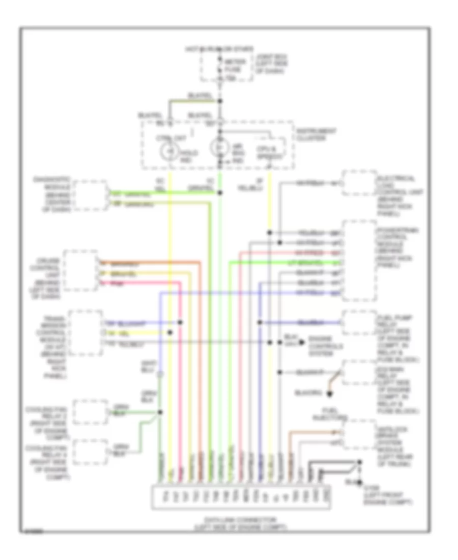
Data Link Connector Wiring Diagram for Mazda RX-7 1995
List of elements for Data Link Connector Wiring Diagram for Mazda RX-7 1995:
- (behind center of dash)
- (right side
- Air bag ind.
- Antilock brake system module (left rear of trunk)
- Compt)
- Cooling fan
- Cpu & speedo
- Cruise control unit (behind left side of dash)
- Ctrl ckt
- Data link connector (left side of engine compt)
- Diagnostic module
- Egi main relay (left side of engine compt, in relay & fuse block)
- Electrical load control unit (behind right kick panel)
- Engine controls system
- F/p
- Fab
- Fat
- Fbs
- Fen
- Fsc
- Fuel
- Fuel pump relay (left side of engine compt, in relay & fuse block)
- G108 (left front engine compt)
- Gnd
- Hold ind.
- Hot in run or start
- Ig-
- Injectors
- Instrument cluster
- Joint box (left side of dash)
- L pnk
- Men
- Meter fuse 15a
- Of engine
- Pnk
- Powertrain control module (behind right kick panel)
- Relay 2
- Relay 4
- Tab
- Tat
- Tbs
- Ten
- Tfa
- Trans- mission control module (w/ a/t) (behind right kick panel)
- Tsc
 English