COMPUTER DATA LINES
Data Link Connector Wiring Diagram for Mercedes-Benz S500 2002

List of elements for Data Link Connector Wiring Diagram for Mercedes-Benz S500 2002:
- Airmatic control module
- Can-b h
- Can-b l
- Can-c h
- Can-c l
- Can-d h
- Can-d l
- Central gateway control module
- Comand operating, display & control unit
- Data link connector (dlc) (beneath left side of dash, left of steering column)
- Diag
- Dtr control module
- Electronic ignition- starter switch (eis) control module
- Electronic selector lever control module
- Engine control module (me-sfi) (right rear of engine compt)
- Esp/sps/bas control module
- Etc control module
- Fuse 10a
- Fuse 5a
- Headlamp range adjustment control module
- High/low bus circuit
- Hot at all times
- Hot in run or start
- Instrument cluster
- L10
- L13
- Left fuse box (on left rear corner of engine compt)
- Restraint system control module
- Steering column module
- Tele aid control module
- W36/2 (right footwell)
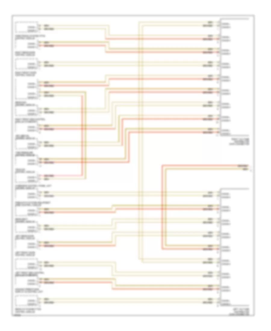
High/Low Bus Wiring Diagram (1 of 2) for Mercedes-Benz S500 2002
List of elements for High/Low Bus Wiring Diagram (1 of 2) for Mercedes-Benz S500 2002:
- Can-b h
- Can-b l
- Comand operationg, display & control unit
- Keyless go control module
- Left front door control module
- Left front esa control module (w/memory)
- Left rear door control module
- Left voltage distributor (can) connector
- Overhead control panel unit control module
- Parktronic system (pts) control module
- Pneumatic system equipment (pse) control module
- Rear a/c pushbutton control module
- Rear sam control module
- Rear seat control module
- Right front door control module
- Right front esa control module (w/memory)
- Right rear door control module
- Right voltage distributor (can) connector
- Tele aid control module
- Tire pressure control module
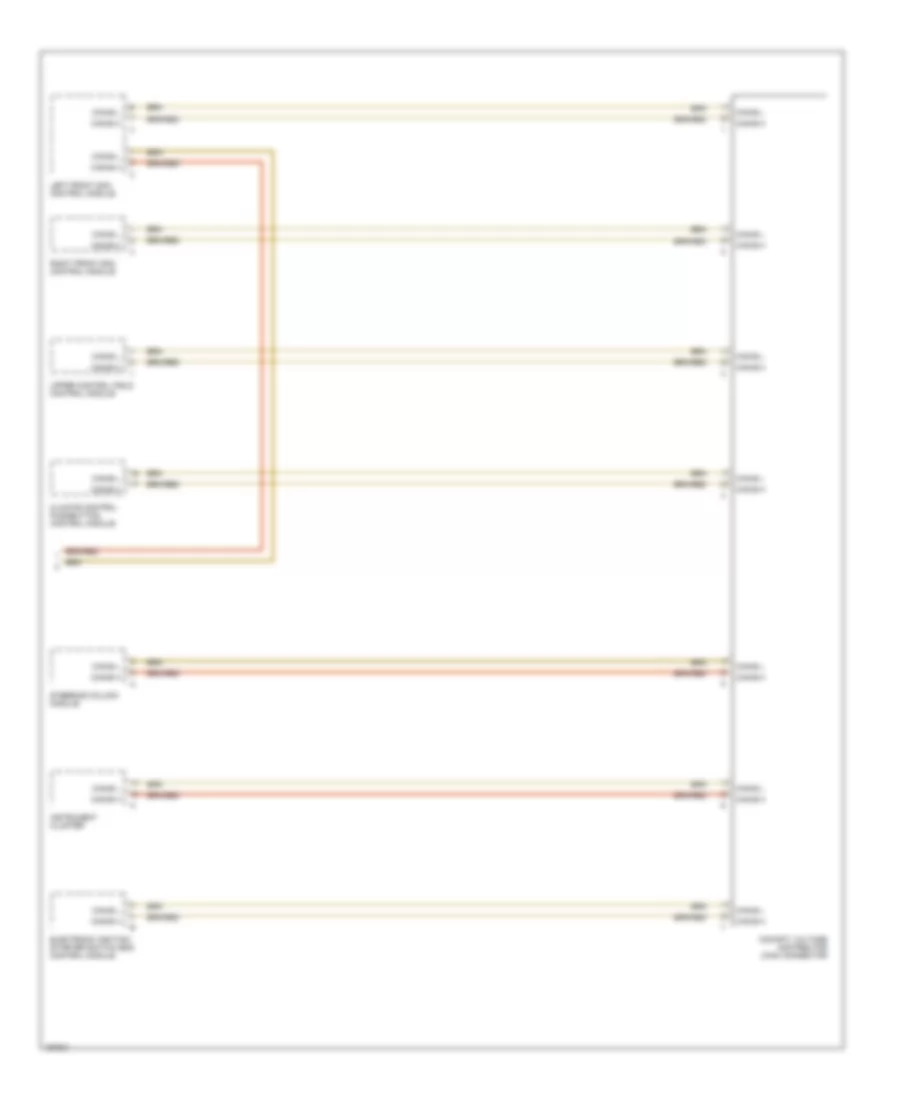
High/Low Bus Wiring Diagram (2 of 2) for Mercedes-Benz S500 2002
List of elements for High/Low Bus Wiring Diagram (2 of 2) for Mercedes-Benz S500 2002:
- Can-b h
- Can-b l
- Climate control pushbutton control module
- Cockpit voltage distributor (can) connector
- Electronic ignition- starter switch (eis) control module
- Instrument cluster
- Left front sam control module
- Right front sam control module
- Steering column module
- Upper control field control module