COMPUTER DATA LINES
Computer Data Lines Wiring Diagram, Evolution for Mitsubishi Lancer ES 2003

List of elements for Computer Data Lines Wiring Diagram, Evolution for Mitsubishi Lancer ES 2003:
- (behind instrument cluster)
- (on right side of transaxle)
- Abs ecu (on right rear of engine compt)
- C01
- C115
- C117
- C12
- C14
- C15
- C214
- C228
- Combination meter
- Data link connector (below left side of dash)
- Engine control module (behind glove box)
- Etacs ecu
- Fuse 15a
- G7 (at top left side of dash)
- Hot at all times
- Joint connector 2
- Joint connector 4
- Joint connector 5 (behind instrument cluster)
- Joint connector 6 (behind lower center of dash)
- Junction block (behind left end of dash)
- Srs ecu (behind lower center of dash)
- Vehicle speed sensor
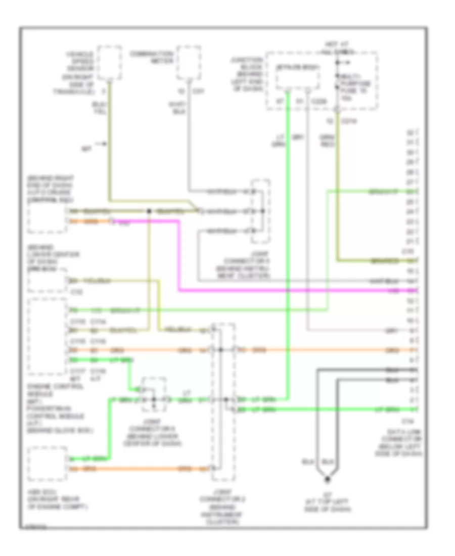
Computer Data Lines Wiring Diagram, Except Evolution for Mitsubishi Lancer ES 2003
List of elements for Computer Data Lines Wiring Diagram, Except Evolution for Mitsubishi Lancer ES 2003:
- (behind instrument cluster)
- (behind lower center of dash) srs ecu
- (behind right end of dash) auto cruise control ecu
- (on right side of transaxle)
- Abs ecu (on right rear of engine compt)
- C01
- C114
- C115
- C116
- C116 a/t
- C117
- C12
- C14
- C15
- C214
- C228
- Combination meter
- Data link connector (below left side of dash)
- Engine control module (m/t) powertrain control module (a/t) (behind glove box)
- Etacs ecu
- G7 (at top left side of dash)
- Hot at all times
- Joint connector 2
- Joint connector 5 (behind instru- ment cluster)
- Joint connector 6 (behind lower center of dash)
- Junction block (behind left end of dash)
- M/t
- Multi- purpose fuse 15 15a
- Vehicle speed sensor