COMPUTER DATA LINES
Computer Data Lines Wiring Diagram, Evolution for Mitsubishi Lancer ES 2008

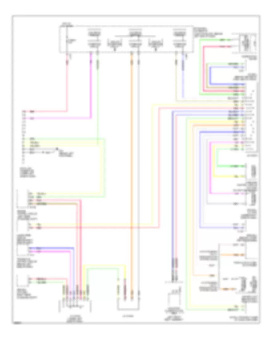
List of elements for Computer Data Lines Wiring Diagram, Evolution for Mitsubishi Lancer ES 2008:
- A/c ecu (behind center of dash)
- A/t
- Analog interface circuit
- Asc ecu (near strut tower)
- B-10
- B-107
- C-22
- C-27
- C-301
- C-317
- C-37
- Can box unit (behind center of dash)
- Can drive circuit
- Can transceiver circuit
- Circuit
- Circuit can drive
- Combination meter
- Cpu
- D39-2
- Data link connector (under left side of dash)
- Engine control module (near relay box)
- Etacs ecu (behind left end of dash)
- Fuse 5 10a
- G18 (behind left kick panel)
- Hands free module (behind glove box)
- Hot at all times
- Interface circuit
- J/c (can1) (behind instrument cluster)
- J/c (can2) (behind instrument cluster)
- J/c (can3) (under front of center console)
- J/c (can4) (a/t) (left rear of engine compt)
- Kos ecu (w/ kos) (under left side of dash)
- Left front seat assembly
- M/t
- Nca
- Occupant classification ecu
- Pnk
- Radio & cd player
- Red
- S-awc-ecu
- Satellite radio tuner (w/ audio amplifier)
- Shift lever (a/t)
- Srs ecu (behind lower center of dash)
- Steering wheel sensor (top of steering column)
- Transaxle ecu (on transmission)
- Transceiver can
- W/ mitsubishi multi- communication system (mmcs)
- W/o mitsubishi multi- communication system (mmcs)
- Wireless control module (w/o kos) (on steering column)
Computer Data Lines Wiring Diagram, Except Evolution for Mitsubishi Lancer ES 2008
List of elements for Computer Data Lines Wiring Diagram, Except Evolution for Mitsubishi Lancer ES 2008:
- A/c ecu (behind center of dash, below radio)
- Abs ecu (w/o asc) (right rear of engine compt)
- Analog interface circuit
- B-109
- C-122
- C-20
- C-301
- C-317
- C-41
- Can box unit (behind right side of dash)
- Can drive circuit
- Can transceiver circuit
- Circuit
- Circuit can drive
- Combination meter
- Cpu
- D35-2
- Data link connector (under left side of dash)
- Engine control module (left rear of engine compt)
- Etacs ecu (on rear of junction block, behind left end of dash)
- Fuse 5 10a
- G14 (behind left kick panel)
- Hands free module (behind right side of dash)
- Hot at all times
- Interface circuit
- J/c (can1)
- J/c (can2)
- J/c (can3) (under left side of dash)
- Kos ecu (w/ kos) (under right side of dash)
- Left front seat assembly
- Nca
- Occupant classification ecu
- Pnk
- Radio & cd player/ cd changer
- Red
- Satellite radio tuner (w/ audio amplifier)
- Srs ecu (behind lower center of dash)
- Transaxle control module (behind left side of dash)
- Transceiver can
- W/ mitsubishi multi- communication system (mmcs)
- W/o mitsubishi multi- communication system (mmcs)
- Wireless control module (w/o kos) (on ignition switch)