COMPUTER DATA LINES
2.0L
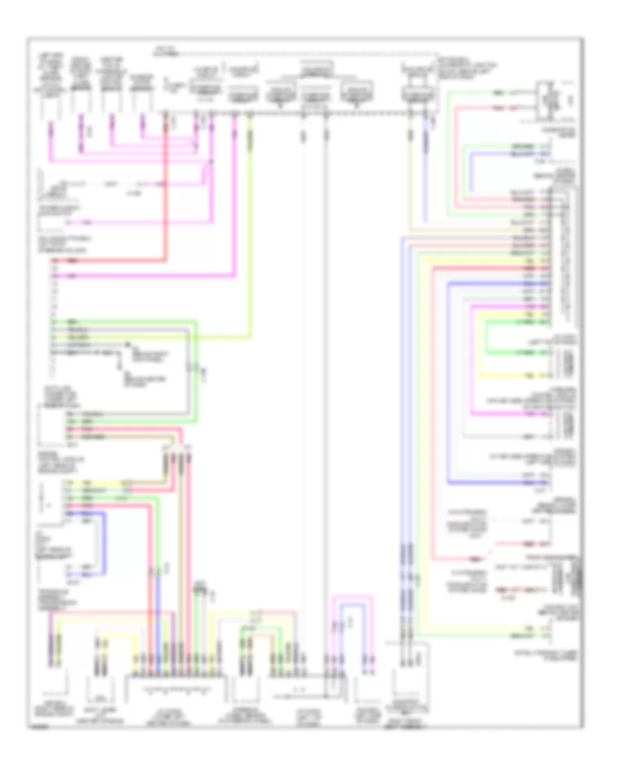
2.0L, Computer Data Lines Wiring Diagram for Mitsubishi Lancer GT 2013

List of elements for 2.0L, Computer Data Lines Wiring Diagram for Mitsubishi Lancer GT 2013:
- (not used)
- (w/
- (w/o
- A/c-ecu (automatic a/c) heater control unit (manual a/c) (behind center of dash)
- Abs-ecu (w/o asc) asc-ecu (w/ asc) (right rear of engine compt)
- Analog interface circuit
- Asc)
- Automatic a/c
- Awd ecu (2.4l)
- B-109
- C-105
- C-122
- C-126
- C-127
- C-144
- C-20
- C-22
- C-301
- C-316
- C-317
- C-35
- C-41
- C-48
- Can box unit (behind right side of dash)
- Can drive circuit
- Can transceiver circuit
- Circuit can drive
- Column switch-ecu (on top of steering column)
- Combination meter
- Cpu
- D-47
- D35-2
- Data link connector (under left side of dash)
- Electric power steering-ecu (right kick panel)
- Engine control module (left rear of engine compt)
- Etacs-ecu (on rear of junction block, behind left end of dash)
- Fuse 5 10a
- G4 (behind right kick panel)
- G5 (right of accelerator pedal)
- Hot at all times
- Interface circuit
- J/c (can1) (left top of dash)
- J/c (can2) (left side of dash)
- J/c (can3) (under left side of dash)
- Kos-ecu (w/ keyless operating system) (left side of dash)
- Lighting control sensor (center top of windshield)
- Lin cut off control unit (w/ theft alarm sensor) (left end of dash)
- Lin drive circuit
- Manual a/c
- Nca
- Occupant classification ecu
- Pnk
- Power window main switch
- Radio & cd player/ cd changer
- Red
- Right front seat assembly
- Satellite radio tuner (if equipped)
- Srs-ecu (behind lower center of dash)
- Steering wheel sensor (w/ asc) (in steering wheel)
- Sunroof motor assembly
- Theft-alarm sensor (front center of roof)
- Transaxle control module (behind left side of dash)
- W/ mitsubishi multi- communication system (mmcs)
- W/o mitsubishi multi- communication system (mmcs)
- Wireless control module (w/o keyless operating system) (on ignition switch)
2.0L TURBO
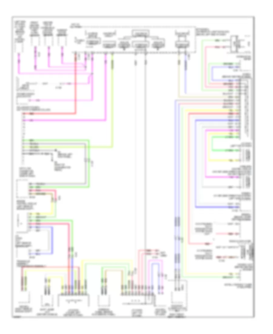
2.0L Turbo, Computer Data Lines Wiring Diagram, Evolution for Mitsubishi Lancer GT 2013
List of elements for 2.0L Turbo, Computer Data Lines Wiring Diagram, Evolution for Mitsubishi Lancer GT 2013:
- (center top of windshield) lighting control sensor
- (front center of roof) theft alarm sensor
- (left end of dash) (w/ theft alarm sensor) lin cut oof control unit
- (left top of dash)
- (not used)
- A-13
- A/c-ecu (behind center of dash)
- A/t
- Analog interface circuit
- Asc-ecu (right rear of engine compt)
- Awc-ecu (left side of dash)
- B-10
- B-107
- C-108
- C-129
- C-130
- C-19
- C-22
- C-23
- C-301
- C-316
- C-317
- C-37
- C-41
- Can box unit (behind center of dash)
- Can drive circuit
- Can transceiver circuit
- Circuit
- Circuit can drive
- Column switch-ecu (on top of steering column)
- Combination meter
- Cpu
- D-45
- D39-2
- Data link connector (under left side of dash)
- Engine control module (left rear of engine compt)
- Etacs ecu (on rear of junction block, behind left end of dash)
- Fuse 5 10a
- G4 (behind right kick panel)
- G6 (behind center of dash)
- Hot at all times
- Interface circuit
- J/c (can1) (left top of dash)
- J/c (can2)
- J/c (can3) (lower left center of dash)
- J/c (can4) (a/t) (left rear of engine compt)
- Kos-ecu (w/ keyless operating system) (left side of dash)
- Lin drive circuit
- M/t
- Nca
- Occupant classification ecu
- Pnk
- Power window main switch
- Radio & cd player
- Red
- Right front seat assembly
- Satellite radio tuner (if equipped)
- Shift lever (a/t) (center console)
- Srs-ecu (behind lower center of dash)
- Steering wheel sensor (in steering wheel)
- Sunroof motor assembly
- Transaxle assembly (transmission assembly)
- Transceiver can
- W/ mitsubishi multi- communication system (mmcs)
- W/o mitsubishi multi- communication system (mmcs)
- Wireless control module (w/o keyless operating system) (on ignition switch)
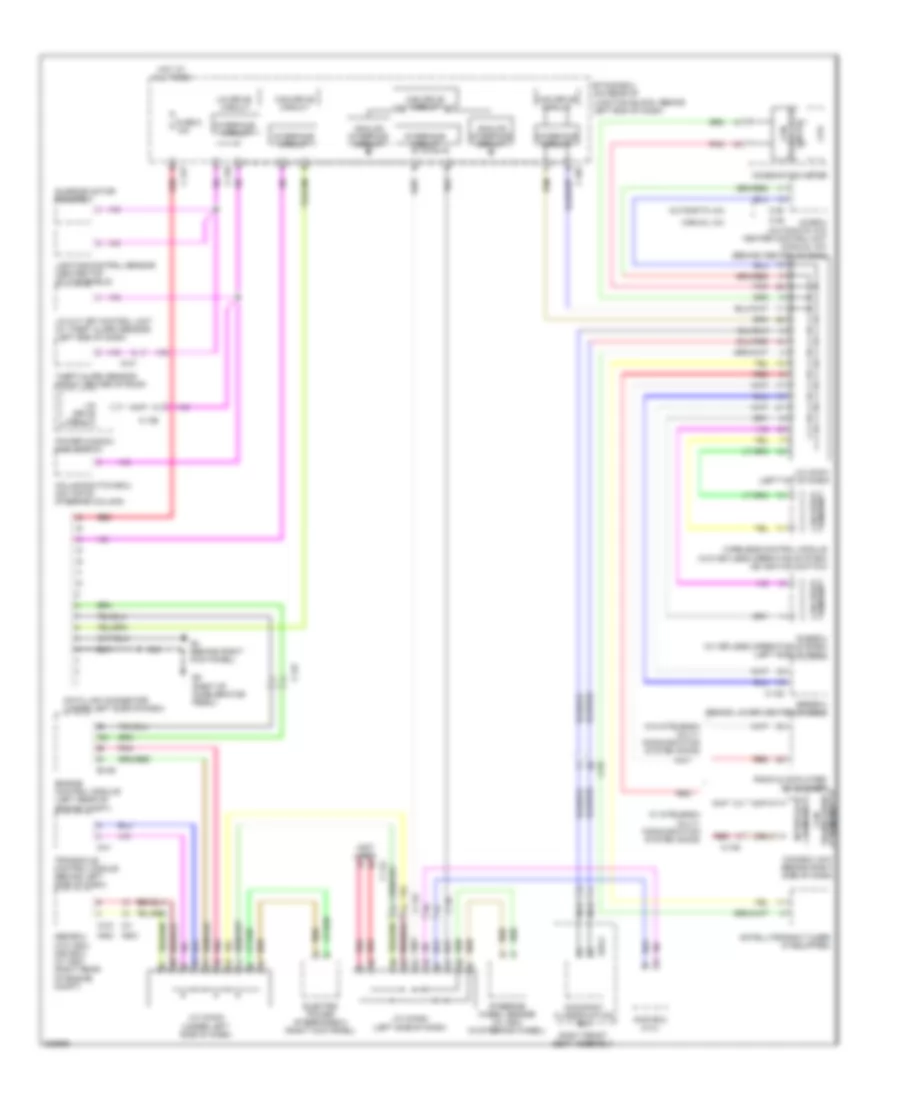
2.0L Turbo, Computer Data Lines Wiring Diagram, Except Evolution for Mitsubishi Lancer GT 2013
List of elements for 2.0L Turbo, Computer Data Lines Wiring Diagram, Except Evolution for Mitsubishi Lancer GT 2013:
- (center top of windshield) lighting control sensor
- (front center of roof) theft alarm sensor
- (left end of dash) (w/ theft alarm sensor) lin cut off control unit
- (left top of dash)
- (not
- A-54
- A/c-ecu (behind center of dash)
- Analog interface circuit
- Asc-ecu (right rear of engine compt)
- Awc-ecu (left side of dash)
- B-109
- B-120
- C-105
- C-122
- C-126
- C-127
- C-144
- C-20
- C-22
- C-301
- C-316
- C-317
- C-35
- Can box unit (behind center of dash)
- Can drive circuit
- Can transceiver circuit
- Circuit can drive
- Column switch-ecu (on top of steering column)
- Combination meter
- Cpu
- D-47
- D35-2
- Data link connector (under left side of dash)
- Engine control module (left rear of engine compt)
- Etacs-ecu (on rear of junction block, behind left end of dash)
- Fuse 5 10a
- G4 (behind left kick panel)
- G5 (right of accelerator pedal)
- Hot at all times
- Interface circuit
- J/c (can1) (left top of dash)
- J/c (can2)
- J/c (can3) (lower left center of dash)
- J/c (can4) (a/t) (left rear of engine compt)
- Kos-ecu (w/ keyless operating system) (left side of dash)
- Lin drive circuit
- Nca
- Occupant classification ecu
- Pnk
- Power window main switch
- Radio & cd player
- Red
- Right front seat assembly
- Satellite radio tuner (if equipped)
- Shift lever (a/t) (center console)
- Srs-ecu (behind lower center of dash)
- Steering wheel sensor (in steering wheel)
- Sunroof motor assembly
- Transaxle assembly (transmission assembly)
- Used)
- W/ mitsubishi multi- communication system (mmcs)
- W/o mitsubishi multi- communication system (mmcs)
- Wireless control module (w/o keyless operating system) (on ignition switch)
2.4L
2.4L, Computer Data Lines Wiring Diagram for Mitsubishi Lancer GT 2013
List of elements for 2.4L, Computer Data Lines Wiring Diagram for Mitsubishi Lancer GT 2013:
- (not used)
- (w/
- (w/o
- A/c-ecu (automatic a/c) heater control unit (manual a/c) (behind center of dash)
- Abs-ecu (w/o asc) asc-ecu (w/ asc) (right rear of engine compt)
- Analog interface circuit
- Asc)
- Automatic a/c
- Awd ecu (2.4l)
- B-109
- C-105
- C-122
- C-126
- C-127
- C-144
- C-20
- C-22
- C-301
- C-316
- C-317
- C-35
- C-41
- C-48
- Can box unit (behind right side of dash)
- Can drive circuit
- Can transceiver circuit
- Circuit can drive
- Column switch-ecu (on top of steering column)
- Combination meter
- Cpu
- D-47
- D35-2
- Data link connector (under left side of dash)
- Electric power steering-ecu (right kick panel)
- Engine control module (left rear of engine compt)
- Etacs-ecu (on rear of junction block, behind left end of dash)
- Fuse 5 10a
- G4 (behind right kick panel)
- G5 (right of accelerator pedal)
- Hot at all times
- Interface circuit
- J/c (can1) (left top of dash)
- J/c (can2) (left side of dash)
- J/c (can3) (under left side of dash)
- Kos-ecu (w/ keyless operating system) (left side of dash)
- Lighting control sensor (center top of windshield)
- Lin cut off control unit (w/ theft alarm sensor) (left end of dash)
- Lin drive circuit
- Manual a/c
- Nca
- Occupant classification ecu
- Pnk
- Power window main switch
- Radio & cd player/ cd changer
- Red
- Right front seat assembly
- Satellite radio tuner (if equipped)
- Srs-ecu (behind lower center of dash)
- Steering wheel sensor (w/ asc) (in steering wheel)
- Sunroof motor assembly
- Theft-alarm sensor (front center of roof)
- Transaxle control module (behind left side of dash)
- W/ mitsubishi multi- communication system (mmcs)
- W/o mitsubishi multi- communication system (mmcs)
- Wireless control module (w/o keyless operating system) (on ignition switch)