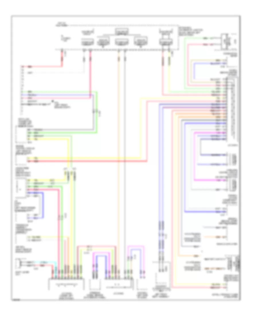
COMPUTER DATA LINES
2.0L
2.0L, Computer Data Lines Wiring Diagram for Mitsubishi Lancer Ralliart 2010

List of elements for 2.0L, Computer Data Lines Wiring Diagram for Mitsubishi Lancer Ralliart 2010:
- (not used)
- A/c ecu (w/ air conditioning) heater control unit (w/o air conditioning) (behind center of dash)
- Analog interface circuit
- Asc ecu (right rear of engine compt)
- B-109
- C-105
- C-122
- C-128
- C-133
- C-20
- C-301
- C-317
- C-35
- C-41
- C-48
- C-51
- Can box unit (behind right side of dash)
- Can drive circuit
- Can transceiver circuit
- Circuit can drive
- Combination meter
- Cpu
- D35-2
- Data link connector (under left side of dash)
- Engine control module (left rear of engine compt)
- Etacs ecu (on rear of junction block, behind left end of dash)
- Fuse 5 10a
- G14 (behind left kick panel)
- Hands free module (behind right side of dash)
- Hot at all times
- Interface circuit
- J/c (can1)
- J/c (can2)
- J/c (can3) (under left side of dash)
- Kos ecu (w/ kos) (under right side of dash)
- Nca
- Occupant classification ecu
- Pnk
- Radio & cd player/ cd changer
- Red
- Right front seat assembly
- Satellite radio tuner (if equipped)
- Srs ecu (behind lower center of dash)
- Steering wheel sensor (in steering wheel)
- Transaxle control module (behind left side of dash)
- W/ air conditioning
- W/ mitsubishi multi- communication system (mmcs)
- W/o air conditioning
- W/o mitsubishi multi- communication system (mmcs)
- Wireless control module (w/o kos) (on ignition switch)
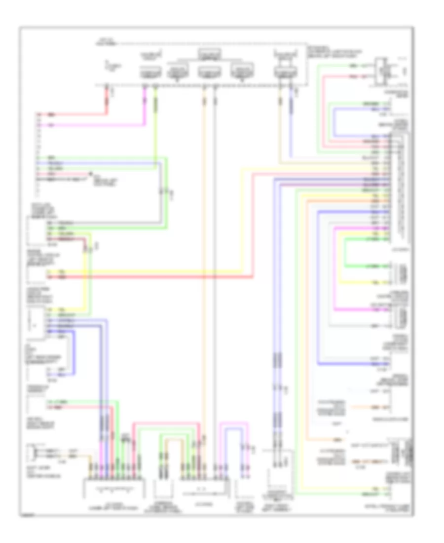
2.0L TURBO
2.0L Turbo, Computer Data Lines Wiring Diagram, Evolution for Mitsubishi Lancer Ralliart 2010
List of elements for 2.0L Turbo, Computer Data Lines Wiring Diagram, Evolution for Mitsubishi Lancer Ralliart 2010:
- A-13
- A/c ecu (behind center of dash)
- A/t
- Analog interface circuit
- Asc ecu (right rear of engine compt)
- Awc-ecu (left side of dash)
- B-10
- B-107
- C-108
- C-131
- C-22
- C-27
- C-301
- C-317
- C-37
- C-41
- Can box unit (behind right side of dash)
- Can drive circuit
- Can transceiver circuit
- Circuit
- Circuit can drive
- Combination meter
- Cpu
- D39-2
- Data link connector (under left side of dash)
- Engine control module (left rear of engine compt)
- Etacs ecu (on rear of junction block, behind left end of dash)
- Fuse 5 10a
- G18 (left front engine compt)
- Hands free module (behind right side of dash)
- Hot at all times
- Interface circuit
- J/c (can1)
- J/c (can2)
- J/c (can3) (under left side of dash)
- J/c (can4) (a/t) (left rear corner of engine compt)
- Kos ecu (w/ kos) (under right side of dash)
- Left front seat assembly
- M/t
- Nca
- Occupant classification ecu
- Pnk
- Radio & cd player
- Red
- Satellite radio tuner (if equipped)
- Shift lever (a/t)
- Srs ecu (behind lower center of dash)
- Steering wheel sensor (in steering wheel)
- Transaxle assembly (transmission assembly)
- Transceiver can
- W/ mitsubishi multi- communication system (mmcs)
- W/o mitsubishi multi- communication system (mmcs)
- Wireless control module (w/o kos) (on ignition switch)
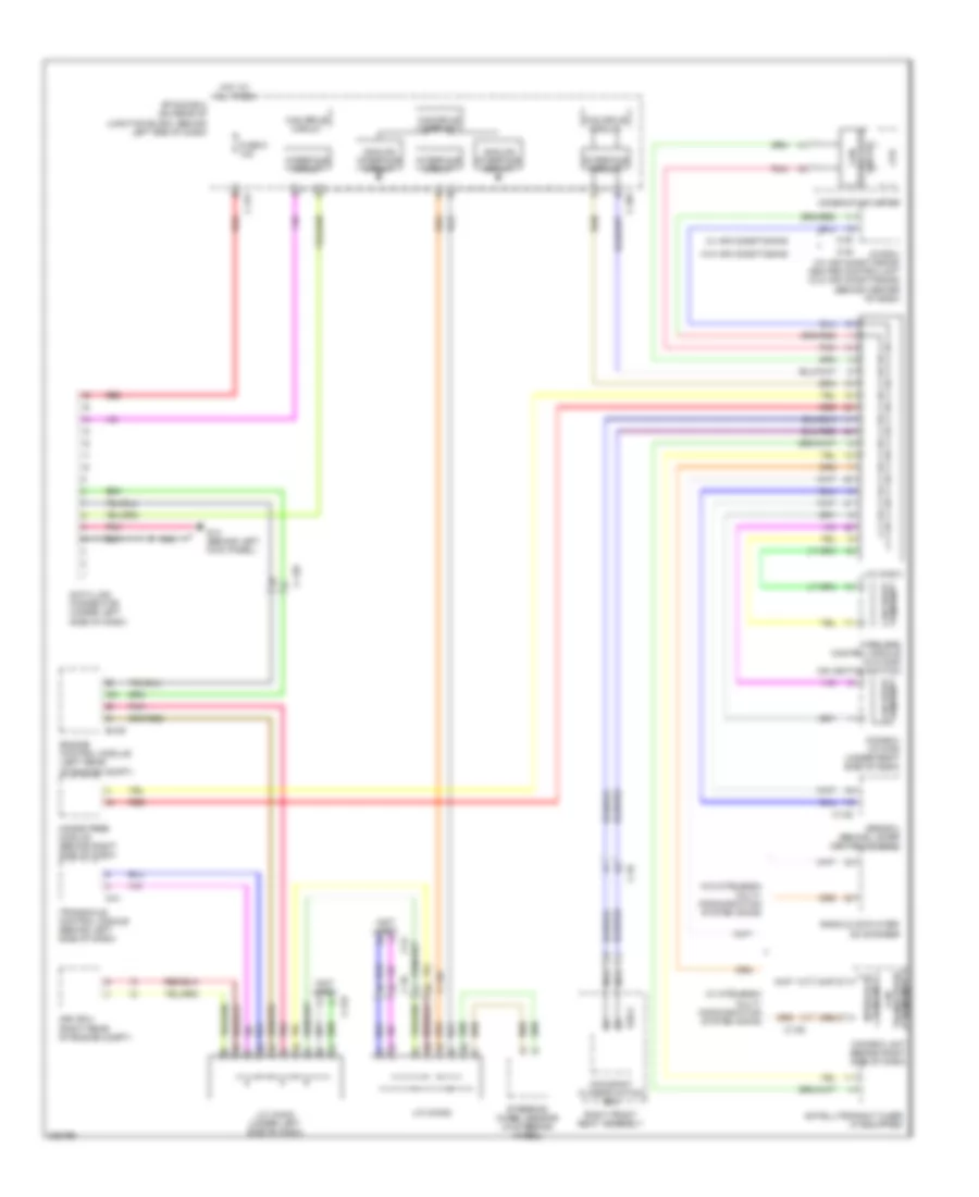
2.0L Turbo, Computer Data Lines Wiring Diagram, Except Evolution for Mitsubishi Lancer Ralliart 2010
List of elements for 2.0L Turbo, Computer Data Lines Wiring Diagram, Except Evolution for Mitsubishi Lancer Ralliart 2010:
- (not used)
- A-54
- A/c ecu (behind center of dash)
- Analog interface circuit
- Asc ecu (right rear of engine compt)
- Awc-ecu (left side of dash)
- B-109
- B-120
- C-105
- C-122
- C-128
- C-133
- C-20
- C-301
- C-317
- C-35
- C-49
- Can box unit (behind right side of dash)
- Can drive circuit
- Can transceiver circuit
- Circuit can drive
- Combination meter
- Cpu
- D35-2
- Data link connector (under left side of dash)
- Engine control module (left rear of engine compt)
- Etacs ecu (on rear of junction block, behind left end of dash)
- Fuse 5 10a
- G14 (behind left kick panel)
- Hands free module (behind right side of dash)
- Hot at all times
- Interface circuit
- J/c (can1)
- J/c (can2)
- J/c (can3) (under left side of dash)
- J/c (can4) (a/t) (left rear corner of engine compt)
- Kos ecu (w/ kos) (under right side of dash)
- Nca
- Occupant classification ecu
- Pnk
- Radio & cd player
- Red
- Right front seat assembly
- Satellite radio tuner (if equipped)
- Shift lever (a/t) (center console)
- Srs ecu (behind lower center of dash)
- Steering wheel sensor (in steering wheel)
- Transaxle assembly
- W/ mitsubishi multi- communication system (mmcs)
- W/o mitsubishi multi- communication system (mmcs)
- Wireless control module (w/o kos) (on ignition switch)
2.4L
2.4L, Computer Data Lines Wiring Diagram for Mitsubishi Lancer Ralliart 2010
List of elements for 2.4L, Computer Data Lines Wiring Diagram for Mitsubishi Lancer Ralliart 2010:
- (not used)
- A/c ecu (w/ air conditioning) heater control unit (w/o air conditioning) (behind center of dash)
- Analog interface circuit
- Asc ecu (right rear of engine compt)
- B-109
- C-105
- C-122
- C-128
- C-133
- C-20
- C-301
- C-317
- C-35
- C-41
- C-48
- C-51
- Can box unit (behind right side of dash)
- Can drive circuit
- Can transceiver circuit
- Circuit can drive
- Combination meter
- Cpu
- D35-2
- Data link connector (under left side of dash)
- Engine control module (left rear of engine compt)
- Etacs ecu (on rear of junction block, behind left end of dash)
- Fuse 5 10a
- G14 (behind left kick panel)
- Hands free module (behind right side of dash)
- Hot at all times
- Interface circuit
- J/c (can1)
- J/c (can2)
- J/c (can3) (under left side of dash)
- Kos ecu (w/ kos) (under right side of dash)
- Nca
- Occupant classification ecu
- Pnk
- Radio & cd player/ cd changer
- Red
- Right front seat assembly
- Satellite radio tuner (if equipped)
- Srs ecu (behind lower center of dash)
- Steering wheel sensor (in steering wheel)
- Transaxle control module (behind left side of dash)
- W/ air conditioning
- W/ mitsubishi multi- communication system (mmcs)
- W/o air conditioning
- W/o mitsubishi multi- communication system (mmcs)
- Wireless control module (w/o kos) (on ignition switch)