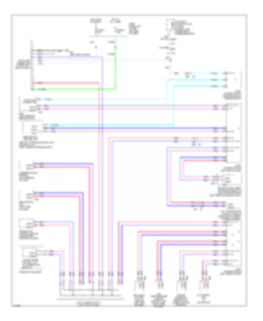
COMPUTER DATA LINES
Computer Data Lines Wiring Diagram for Nissan NV200 Taxi 2014
List of elements for Computer Data Lines Wiring Diagram for Nissan NV200 Taxi 2014:
- (forward of fuse & fusible link box)
- 11a
- 12a
- 17b
- 18b
- 25a
- Abs actuator & electric unit (control unit) (right rear of engine compt)
- Abs/tcs/vdc control unit
- Air bag diagnosis sensor unit (under center console)
- Av control unit (w/ navigation)
- B11
- Bcm (body control module) (left end of dash)
- Can-h
- Can-l
- Combination meter
- Cpu
- Data link connector
- Data link connector (under left end of dash)
- Dia k
- E16
- E46
- Ecm (left rear of engine compt)
- Eps control unit (left side of dash)
- Fuse 10 10a
- Fuse 3 10a
- Fuse block (j/b) (lower left end of dash)
- Hot at all times
- Hot in on or start
- Ipdm e/r (intelligent power distribution module engine room) (left rear of engine compt)
- Joint connector e01 (center rear of engine compt)
- Joint connector e02 (left end of dash)
- Joint connector m01 (left side of dash)
- Joint connector m02 (left side of dash)
- K-line
- Low tire pressure warning control unit (right side of dash)
- M12
- M18
- M35
- M53
- M61 (left end of dash)
- M69
- M70
- Occupant classification system control unit (under front passenger seat)
- Pnk
- Steering angle sensor (on steering column)
- Tcm (transmission control module)
- Telematics control module (if equipped) (center of dash)
- Unified meter control unit (w/ information display)
 English