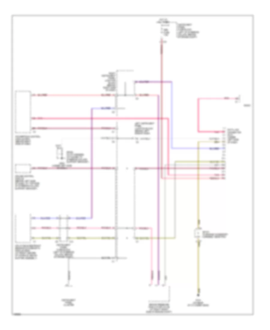
COMPUTER DATA LINES
Computer Data Lines Wiring Diagram for Pontiac Vibe GT 2004
List of elements for Computer Data Lines Wiring Diagram for Pontiac Vibe GT 2004:
- Brake pressure modulator valve (at right front side of engine compt)
- C10
- Cruise control module (behind left side of dash, at top side of steering column support bracket)
- Data link connector (dlc) (under left side of dash)
- G104 (on rear of cylinder head)
- G200 (under left side of dash)
- Hot at all times
- Inflatable restraint sensing & diagnostic module (sdm) (at front center of console, below shifter assembly)
- Instrument panel cluster
- Instrument panel fuse block (left of steering column, behind storage compt)
- Left instrument panel junction block (behind left side of dash)
- Obd fuse 7.5a
- Pnk
- Powertrain control module (pcm) (behind right side of dash)
- Radio
- Right instrument panel junction block (behind right side of dash)
- Sp107 (in engine accessory harness, near pcm)
- Sp200 (in i/p harness, attached to steering column support bracket)
 English