COMPUTER DATA LINES
Computer Data Lines Wiring Diagram for Subaru B9 Tribeca 2006
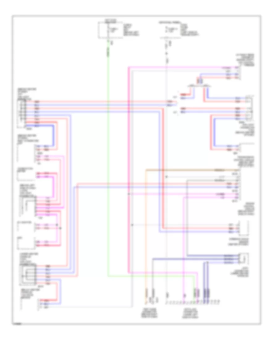
List of elements for Computer Data Lines Wiring Diagram for Subaru B9 Tribeca 2006:
- (at right rear corner of engine compt) vdc control module
- (behind center of dash) (int) can joint connector
- (behind center of dash) body integrated unit
- (behind left side of dash) (l-can) can joint connector
- (below center console) yaw rate sensor
- (under center console) (yaw) can joint connector
- (under left side of dash)
- A/t
- B135
- B136
- B137
- B186
- B280
- B352
- B355
- B416
- B420
- B421
- B52
- B54
- Can joint connector (tcm) (behind center of dash)
- Combination meter
- Data link connector
- Engine control module (behind right side of dash)
- Fuse & relay box (behind left end of dash)
- Fuse 13 7.5a
- Fuse 4 15a
- Hot at all times
- Hot in on or start
- I128
- I84
- Joint connector (under center console)
- M/t
- Main fuse box (left side of engine compt)
- Mfd
- Pnk
- Red
- Steering angle sensor (center of dash)
- Test mode connector (behind right side of dash)
- Transmission control module (behind left side of dash)
- Tv monitor
 English