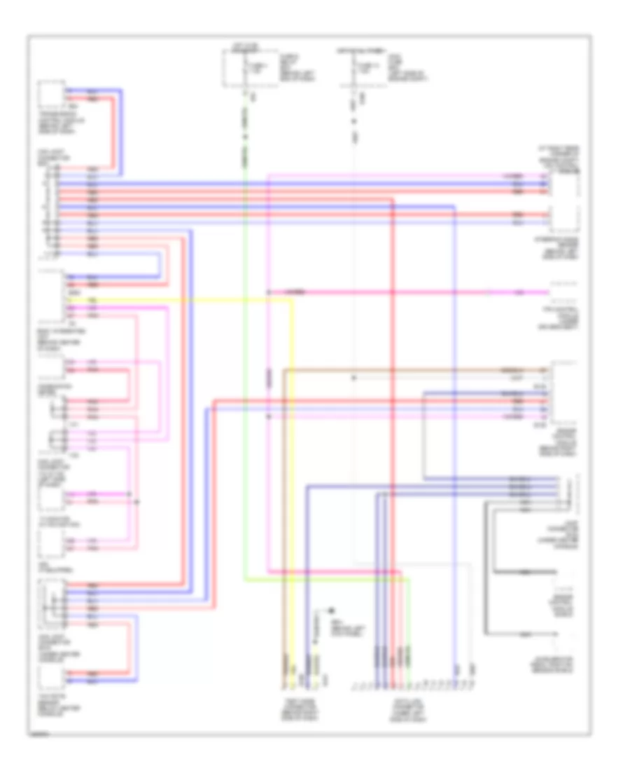
COMPUTER DATA LINES
Computer Data Lines Wiring Diagram for Subaru B9 Tribeca 2007
List of elements for Computer Data Lines Wiring Diagram for Subaru B9 Tribeca 2007:
- (at right rear corner of engine compt) vdc control module
- (under left side of dash)
- Accelerator pedal position sensor shield
- B135
- B136
- B186
- B280
- B420
- B421
- B52
- B54
- Body integrated unit (behind center of dash)
- Can joint connector b331
- Can joint connector b416 (under center console)
- Can joint connector i141 & i142 (left side of dash)
- Combination meter
- Data link connector
- Engine control module (behind right side of dash)
- Engine control module shield
- Fuse & relay box (behind left end of dash)
- Fuse 13 7.5a
- Fuse 4 7.5a
- Gb-4 (behind left kick panel)
- Hot at all times
- Hot in on or start
- I141
- I142
- I84
- Joint connector b122 (under center console)
- Main fuse box (left side of engine compt)
- Mfd (if equipped)
- Nca
- Pnk
- Red
- Steering angle sensor (behind left side of dash)
- Test mode connector (behind right side of dash)
- Tpm control module (under driver's seat)
- Transmission control module (behind left side of dash)
- Tv monitor (w/ navigation)
- Yaw rate sensor (below center console)
 English