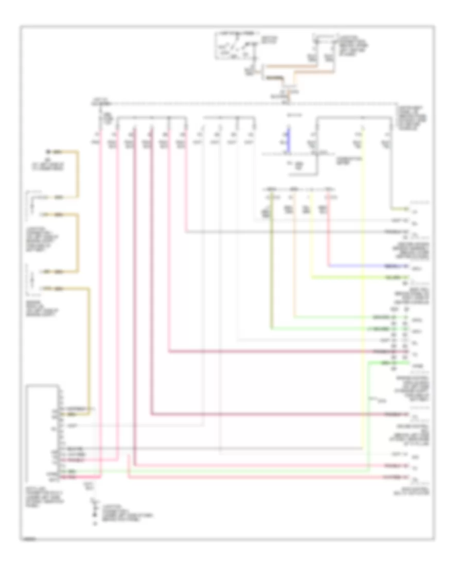
COMPUTER DATA LINES
Computer Data Lines Wiring Diagram for Toyota Celica GT 2004
List of elements for Computer Data Lines Wiring Diagram for Toyota Celica GT 2004:
- A/b
- Acc
- Bat
- Body ecu (behind panel on right side of center console)
- C12
- C13
- Center air bag sensor assembly (behind lower center of dash)
- Combination meter
- Cruise control ecu (behind left side of dash, near base of "a" pillar)
- D/g
- Data link connector (dlc) 3 (under left side of dash, near kick panel)
- Ed (at left side of cylinder head)
- Engine control module (ecm) (on left side of engine compt, forward of battery)
- Engine room j/b (on left side of engine compt)
- F13
- F18
- Forward of battery)
- Gts
- Hot at all times
- Ignition switch
- Instrument panel j/b (behind panel on right side of center console)
- Junction connector 1 (on left side of engine compt,
- Junction connector 3 (under left side of dash, behind kick panel)
- Junction connector 6 (behind upper left center of dash)
- Lock
- Mpx+
- Mpx-
- Mpx1
- Mpx2
- Obd fuse 7.5a
- Off
- Pnk
- Sil
- Skid control ecu w/ actuator
- Srs ind
- Start
- Tx+
- Wfse
 English