COMPUTER DATA LINES
Computer Data Lines Wiring Diagram for Toyota ECHO 2004
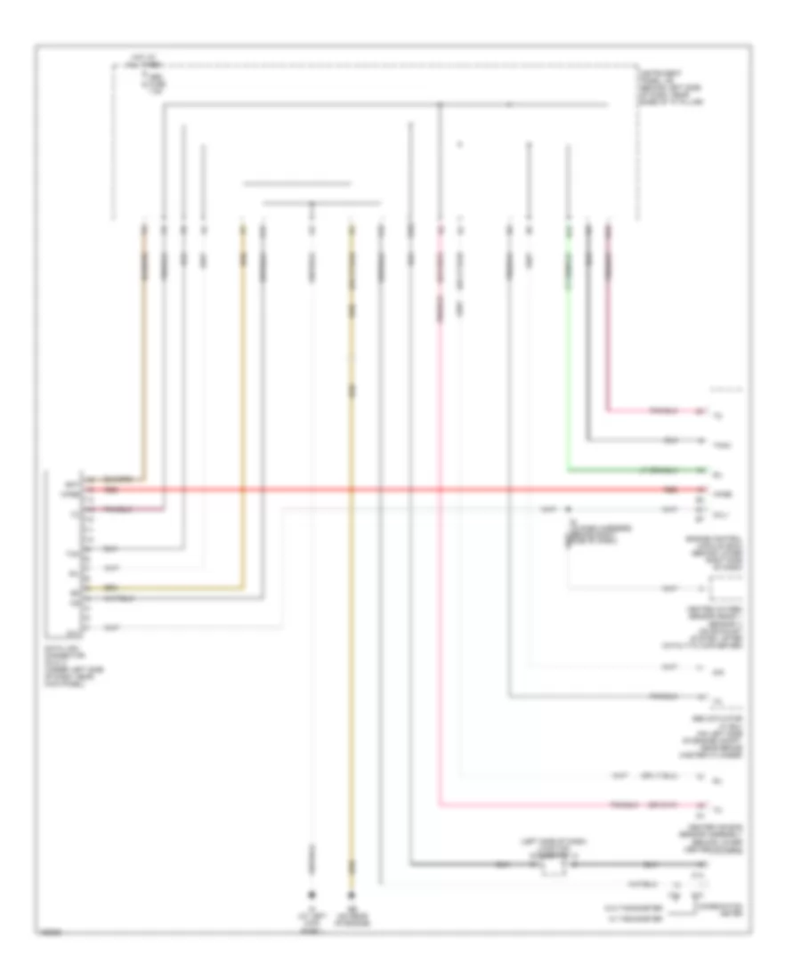
List of elements for Computer Data Lines Wiring Diagram for Toyota ECHO 2004:
- (left side of dash) junction connector 12
- Abs actuator w/ ecu (on left side of engine compt, near brake master cylinder)
- Bat
- C13
- C14
- Center air bag sensor assembly (behind lower center of dash)
- Combination meter
- D/g
- Data link connector (dlc) 3 (under left side of dash, near kick panel)
- Eb (on rear of engine)
- Engine control module (ecm) (behind lower right side of dash)
- F12
- G10
- H12
- H14
- Heated oxygen sensor (bank 1 sensor 1) (on exhaust system, after catalytic converter)
- Hot at all times
- Id (at left kick panel)
- Instrument panel j/b (behind left side of dash, near base of "a" pillar)
- Obd fuse 7.5a
- Ox1
- Oxl1
- P17
- Red
- Sil
- Tac
- Tach
- W/ tachometer
- W/o tachometer
- Wfse
 English