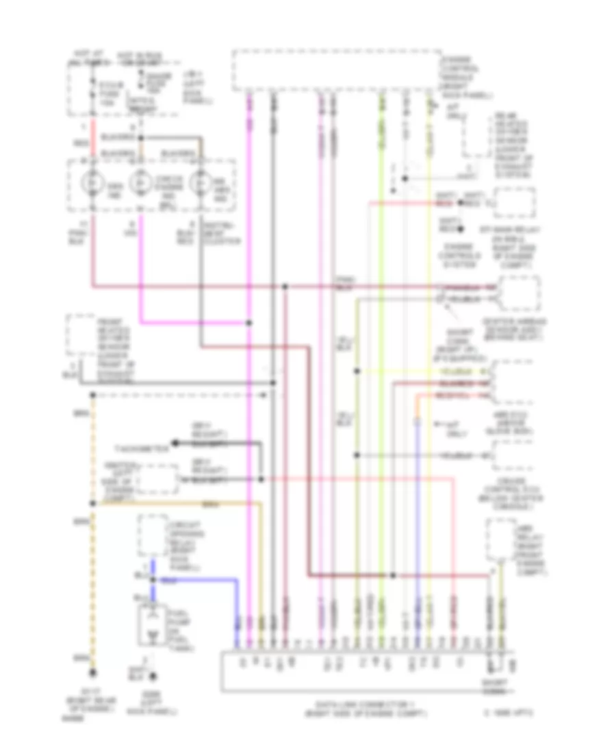
AUTOMOTIVE ELECTRICIANS PORTAL

COMPUTER DATA LINES – Toyota T100 SR5 1994 – SYSTEM WIRING DIAGRAMS

COMPUTER DATA LINES

2.7L

2.7L, Data Link Connector Wiring Diagram for Toyota T100 SR5 1994

2.7L, Data Link Connector Wiring Diagram for Toyota T100 SR5 1994 https://portal-diagnostov.com/license.html
https://portal-diagnostov.com/license.html Automotive Electricians Portal FZCO Automotive Electricians Portal FZCO
Download PDF file

List of elements for 2.7L, Data Link Connector Wiring Diagram for Toyota T100 SR5 1994:

  • (behind center
  • (in r/b-2, right side of engine
  • (left front of engine)
  • (left kick panel)
  • (right i/p)
  • 1995 vftc c
  • Abs ecu (above
  • Abs relay (left front engine compt)
  • All times
  • B-14
  • B-15
  • B-5
  • B-6
  • Center airbag sensor assy. (behind seat)
  • Circuit opening relay (right kick panel)
  • Compt)
  • Console)
  • Control ecu
  • Cruise
  • Data link connector 1 (left side of engine)
  • Ecu-b fuse 15a
  • Efi main relay
  • Engine control module (right kick panel)
  • Engine controls system
  • Front heated oxygen sensor 1 (lower front of exhaust system)
  • Fuel pump (in fuel tank)
  • G110
  • G200
  • Gauge fuse 10a
  • Glove box)
  • Hot at
  • Hot in run or start
  • Ig-
  • Igniter (right
  • Instrument cluster
  • Integ. relay
  • J/b-1 (left kick panel)
  • Ox1
  • Ox2
  • Rear heated oxygen sensor 2 (lower front of exhaust system)
  • Red
  • Rr abs ind.
  • Short conn.
  • Side of engine compt)
  • Srs ind.
  • Tachometer
  • Te1
  • Te2

3.0L

3.0L, Data Link Connector Wiring Diagram for Toyota T100 SR5 1994

3.0L, Data Link Connector Wiring Diagram for Toyota T100 SR5 1994 https://portal-diagnostov.com/license.html
https://portal-diagnostov.com/license.html Automotive Electricians Portal FZCO Automotive Electricians Portal FZCO
Get access to all wiring diagrams of the carDownload PDF file

List of elements for 3.0L, Data Link Connector Wiring Diagram for Toyota T100 SR5 1994:

  • (a/t)
  • (below center
  • (if equipped)
  • (in r/b-2, right side of engine
  • (left
  • (left kick panel)
  • (m/t)
  • (mil)
  • (right i/p)
  • (right rear of engine)
  • (right side of engine compt)
  • 1995 vftc c
  • A-20
  • A-5
  • A/t only
  • Abs ecu (above
  • Abs relay (right front engine compt)
  • All times
  • B-10
  • B-15
  • B-16
  • B-6
  • B-8
  • Center airbag sensor assy. (behind seat)
  • Check engine
  • Circuit opening relay (right kick panel)
  • Compt)
  • Console)
  • Control ecu
  • Cruise
  • Data link connector 1
  • Ecu-b fuse 15a
  • Efi main relay
  • Engine control module (right kick panel)
  • Engine controls system
  • Front heated oxygen sensor (lower front of exhaust system)
  • Fuel pump (in fuel tank)
  • G117
  • G200
  • Gauge fuse 10a
  • Glove box)
  • Hot at
  • Hot in run or start
  • Ig-
  • Igniter
  • Ind.
  • Instru- ment cluster
  • Integ. relay
  • J/b-1 (left kick panel)
  • Ox1
  • Ox2
  • Rear heated oxygen sensor (lower front of exhaust system)
  • Red
  • Rr abs ind.
  • Short conn.
  • Side of engine compt)
  • Srs ind.
  • Tachometer
  • Te1
  • Te2
  • Vf1