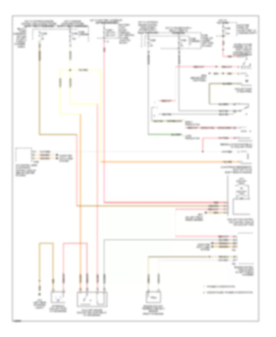
COOLING FAN
Cooling Fan Wiring Diagram for Audi A5 Quattro 2009
List of elements for Cooling Fan Wiring Diagram for Audi A5 Quattro 2009:
- (a/t) coolant fan 2
- (m/t) (a/t)
- (on relay/fuse carrier - sf, at right side of luggage compt) sockets relay
- 11a
- A/c control head climatronic control module (behind center of dash)
- After-run coolant pump (w/ 8z4/8z6/8z9)
- Auxiliary engine coolant (ec) pump relay (w/ 8z4/8z6/8z9)
- Battery jump start terminal (on terminal 30 wire junction block)
- Climatronic refrigerant shut-off valve (right rear of engine)
- Computer data lines system
- Coolant fan
- Coolant fan control (fc) control module (on coolant fan)
- Coolant pump (if equipped)
- Discontinued, phased in modification
- Early production
- Engine control module (ecm) (in left plenum chamber)
- Engine coolant temperature (ect) sensor (front of engine)
- Fuse 1 40a 60a
- Fuse 110a
- Fuse 15a
- Fuse 5a
- Fuse carrier
- Fuse panel sc (under left side of dash)
- G12 (left rear of engine compt)
- G638 (behind right kick panel)
- G671 (on left front cross member)
- Hot at all times
- Hot w/ battery interrupt igniter energized
- Late production
- Main fuse panel sa (on battery, in luggage compt)
- Phased in modification
- Recirculation pump relay (w/ coolant pump)
- Red
- Relay/ fuse carrier e box sb (in left plenum chamber e-box)
- T20e
- T60
- T94
 English