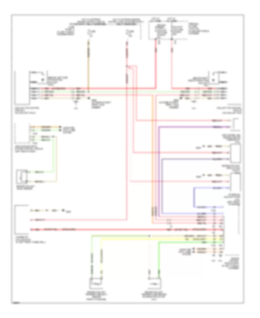
COOLING FAN
Cooling Fan Wiring Diagram for Audi A7 Prestige 2013
List of elements for Cooling Fan Wiring Diagram for Audi A7 Prestige 2013:
- (behind left side of radiator) coolant fan 2
- (behind right side of radiator) coolant fan
- 11a
- 16a
- 3.0l
- 4.0l
- A1a
- After-run coolant pump (4.0l) (left front of engine)
- B2a
- Charge air cooling pump (in left front wheelwell)
- Computer data lines system
- Coolant fan control module (on coolant fan)
- Coolant fan control module 2 (on coolant fan 2)
- Coolant fan fuse 40a/60a/ 80a
- Engine control module (ecm) (in left plenum chamber)
- Engine coolant circulation pump 2 (4.0l)
- Engine coolant level sensor
- Engine coolant temperature (ect) sensor (front of engine)
- Engine coolant temperature sensor on radiator outlet (4.0l)
- Fuse 15a
- Fuse 5a
- Fuse panel a (in left plenum chamber e-box)
- G645
- G685 (outside of right front long member)
- Hot at all times
- Hot w/ motronic engine control module
- Map controlled engine cooling thermostat (4.0l)
- Nca
- Red
- Second speed coolant fan fuse 40a/60a/ 80a
- T105
- T16c
- T32a
- T4fm
- T4fn
- T60
- T91
- T94
- Terminal 30 wire junction (in center plenum chamber)
- Vehicle electrical system control module (left end of dash)
 English