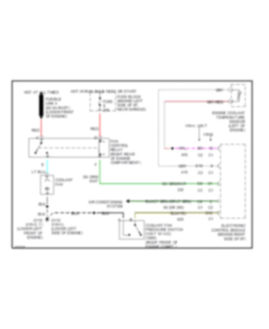
COOLING FAN
Cooling Fan Wiring Diagram for Chevrolet Beretta 1990
List of elements for Cooling Fan Wiring Diagram for Chevrolet Beretta 1990:
- 66 (or 366)
- Air conditioning system
- Coolant fan
- Coolant fan pressure switch (vin t w/ a/c) (1990) (right front of engine compt.)
- D12
- E16
- Electronic control module (behind right side of i/p)
- Engine coolant temperature sensor (left of engine)
- Fan control relay (right rear of engine compartment)
- Fuse 20a
- Fuse block (behind left side of i/p, near shroud)
- Fusible link a (20 ga-rust) (lower front of engine)
- G110 (vin g, t) (lower left front of engine)
- G112 (vin a) (lower left side of engine)
- Hot at all times
- Hot in run, bulb test or start
- Red
- Vin a, vin t
- Vin g
 English