COOLING FAN
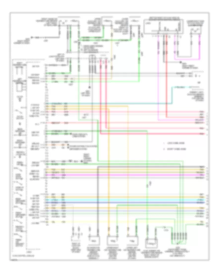
Cooling Fan Wiring Diagram, with A/C for Chevrolet Lumina Euro 1992

List of elements for Cooling Fan Wiring Diagram, with A/C for Chevrolet Lumina Euro 1992:
- (except 3.4l) (3.4l)
- 3.4l
- A/c intermediate pressure sensor (4 cyl) (left front engine compt, in a/c line near accumulator)
- A/c pressure sensor (6 cyl) (left front engine compt, in a/c line near accumulator)
- B20
- C10
- C16
- C21
- D21
- Engine control module (right front engine compt)
- Engine controls system
- Engine coolant temperature sensor (on engine)
- Except 3.4l
- Fusible element l 60a
- Fusible element n 30a 60a
- G110 (left front of engine)
- Hot at all times
- Hot in run
- Ign fuse 10a
- Ign fuse 15a
- Primary coolant fan relay
- Primary cooling fan
- Red
- Right side electrical center (right side of engine compt)
- Secondary coolant fan relay
- Secondary cooling fan
Cooling Fan Wiring Diagram, without A/C for Chevrolet Lumina Euro 1992
List of elements for Cooling Fan Wiring Diagram, without A/C for Chevrolet Lumina Euro 1992:
- (bottom right of hvac module) blower motor control module
- (headliner harness, 105 cm from left sunshade lamp breakout)
- (right front corner of dash) g200
- (under right side of hvac module) blower motor
- 4b7
- 5v ref
- A/c on ind
- A/c on switch
- Air temp
- Air tmp
- Amb tmp
- Ambient light/ sunload sensor assembly (top center of dash)
- B (+)
- Blwr spd
- Computer data lines system
- Defogger system
- Dfrst val
- Duct)
- Evaporator temperature sensor (top right side of hvac assembly)
- Fresh air ind
- Fresh air request switch
- Front defogger ind
- Front defogger switch
- Front inside air temperature sensor (left front of headliner)
- G200 (right front corner of dash)
- G201 (left end of dash)
- Gmlan l
- Gnd
- Ground
- Hvac ambient air temperature sensor (right front of engine compt)
- Hvac control module
- Ign volt
- J203
- J206 (instrument panel harness, approximately 14 cm from x207 breakout)
- J325
- J328
- L air tmp
- Left i/p junction block (left end of dash)
- Left temperature control
- Lf sunld
- Logic
- Long wheel base
- Low ref
- Mode ctrl
- Mode down switch
- Mode up switch
- Pass sunld
- Pnk
- Power distribution system
- R air tmp
- Rear defogger ind
- Rear defogger switch
- Recir ctrl
- Recirc
- Recircu- lation ind
- Recircu- lation switch
- Red
- Rer defg
- Right i/p junction block (right end of dash)
- Right temperature control
- Sens sig
- Short wheel base
- Sns sig
- Spd ctrl
- Sw sig
- Tan
- Temp sig
- Upper auxiliary air temperature sensor (in auxiliary hvac module upper duct)
- Upper left air temperature sensor (top left center of dash)
- Upper right air temperature sensor (top right center of dash)
- X103
- X11
- X207
- X403
- X407