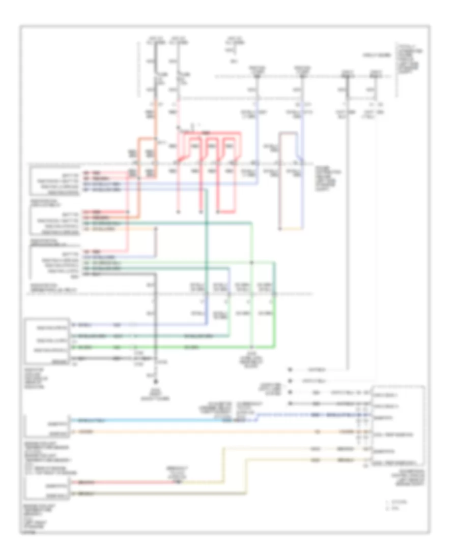
COOLING FAN
Cooling Fan Wiring Diagram for Dodge Avenger Express 2010
List of elements for Cooling Fan Wiring Diagram for Dodge Avenger Express 2010:
- (breakout to c101 & pcm c2) s184
- (in breakout to c101 & pcm c2) (2.4l) s181
- (in injector harness, below throttle body) (2.7l/3.5l) s182
- 2.4l
- 2.7l/3.5l
- A10
- B(+)
- B10
- Batt fd
- C105
- C108
- C11
- Can c bus (+)
- Can c bus (-)
- Circuit board
- Computer data lines system
- Cool temp snsr sig
- Cool temp snsr sig 2
- D64
- D65
- Engine coolant temperature sensor (2.7l/3.5l) engine coolant temperature sensor 1 (2.4l) (2.4l: rear of engine) (2.7l: top front of engine)
- Engine coolant temperature sensor 2 (2.4l) (left front of engine)
- Fuse 10a
- Fuse 40a
- G102 (right shock tower)
- Gnd
- Ground
- Hot at all times
- K222
- K900
- K915
- N210
- N23
- N24
- Nca
- Power distribution center (left side of engine compt)
- Powertrain control module (left rear of engine compt)
- Rad fan hi spd sig
- Rad fan lo rtn
- Rad fan lo spd sig
- Rad fan mtr fd
- Rad fan mtr fd 2
- Rad fan rly batt fd
- Radiator cooling fan module (rear of radiator)
- Radiator fan high/low relay
- Radiator fan medium/high relay
- Radiator fan series/parallel relay
- Red
- S110
- S111
- S125 (wire loom, near relay block)
- S135
- Snsr rtn
- Snsr rtn3
- Snsr sig
- Snsr sig 2
- Totally integrated power module (left side of engine compt)
- Z901
 English