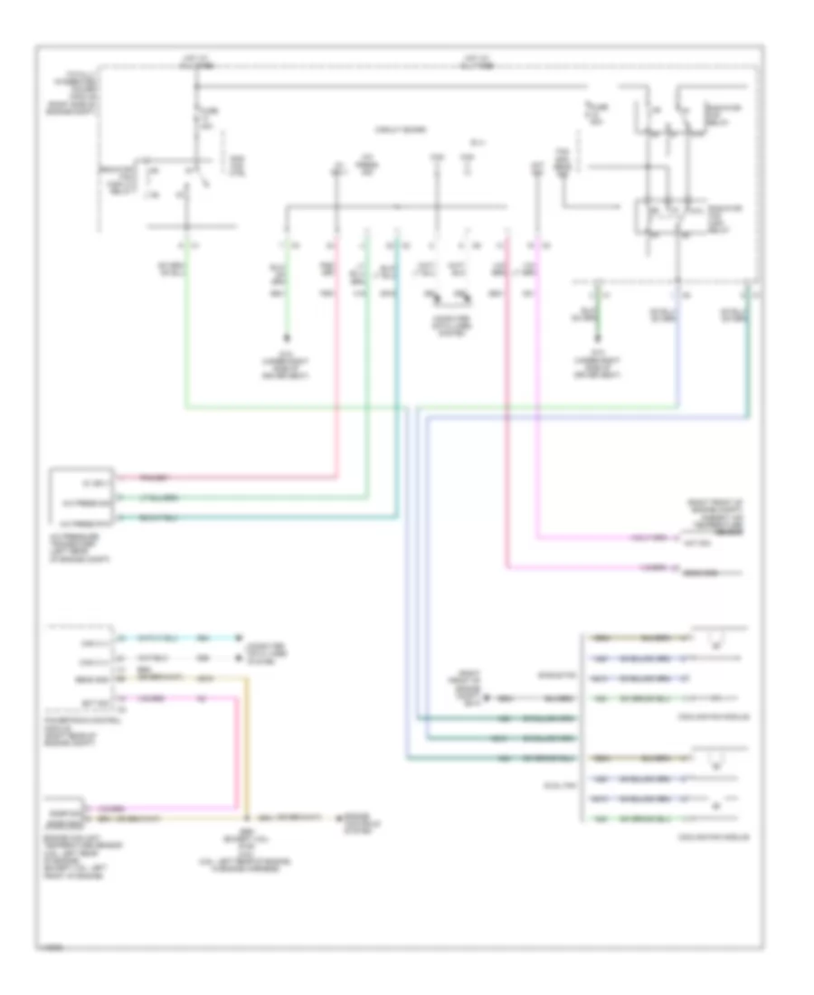
COOLING FAN
Cooling Fan Wiring Diagram for Dodge Challenger R/T 2014
List of elements for Cooling Fan Wiring Diagram for Dodge Challenger R/T 2014:
- (right front of engine compt) ambient air temperature sensor
- (right front of engine compt) g51a
- 5v sply
- 87a
- A/c press rtn
- A/c press sig
- A/c pressure transducer (left rear of engine compt)
- Aat sig
- B (+)
- C18
- C918
- Can c (+)
- Can c (-)
- Circuit board
- Computer data lines system
- Cooling fan module
- D64
- D65
- Dual fan
- Ect sig
- Engine controls system
- Engine coolant temperature sensor (3.6l: left rear of engine) (except 3.6l: left front of engine)
- F891
- Fan spd sens sig
- Fuse 40a
- Fuse 50a
- G1a (under right side of driver seat)
- G31
- G931
- Hot at all times
- K915
- N210
- N23
- N24
- Powertrain control module (right rear of engine compt)
- Rad fan ctrl
- Radiator fan high relay
- Radiator fan high/lo relay
- Radiator fan relay
- S991 (except 3.6l) s155 (3.6l) (3.6l: left rear of engine, in engine harness)
- Sens gnd
- Single fan
- Snsr gnd
- Snsr sig
- Totally integrated power module (right side of engine compt)
- Z901
- Z904
 English