COOLING FAN
Cooling Fan Wiring Diagram for Ford Econoline E250 2008
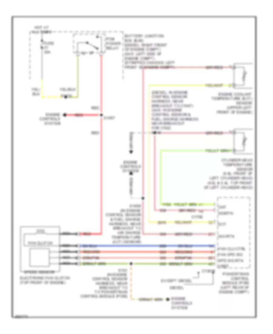
List of elements for Cooling Fan Wiring Diagram for Ford Econoline E250 2008:
- (4.6l & 5.4l: top front of left cylinder head)
- (diesel: in engine control sensor harness, near breakout to c1047) (gas: in engine control sensor & fuel charge harness, near breakout for c192) s136
- Battery junction box (bjb) (diesel: right front of engine compt) (gas: left side of engine compt) (stripped chassis: left front of engine compt)
- C1381e
- C175e
- Cht
- Cylinder head temperature sensor (6.8l: front of left cylinder head)
- Diesel
- Ect
- Electronic fan clutch (top front of engine)
- Engine controls system
- Engine coolant temperature (ect) sensor (upper left front of engine)
- Except diesel
- Fan clu ctrl
- Fan clutch
- Fan spd sig
- Fuse 30a
- Hot at all times
- Nca
- Pcm power relay
- Powertrain control module (pcm) (left rear of engine compt)
- Red
- S101 (in engine control sensor harness, near breakout to to powertrain control module (pcm))
- S1033
- S1057
- S1059 (in engine control sensor & fuel charge harness, near breakout to air charge temperature (act) sensor)
- Sig rtn
- Sigrtn
- Spd sig rtn
- Speed sensor
- Vref
 English