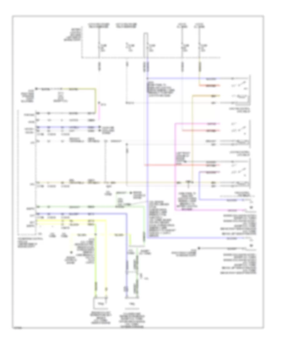
COOLING FAN
Cooling Fan Wiring Diagram for Ford Explorer Sport 2014
List of elements for Cooling Fan Wiring Diagram for Ford Explorer Sport 2014:
- (3.5l) s156 (3.5l turbo) s1006
- (3.5l: engine control sensor & fuel charge wiring assembly, near breakout fuel injector 3) (3.5l turbo: engine control sensor & fuel charge wiring assembly, near breakout to camshaft position 11 (cmp11) sensor)
- (dash panel to headlamp junction wiring assembly, near breakout to battery junction
- (left front corner of engine compt) g103
- 2.0l turbo
- 3.5l
- 3.5l turbo
- Battery junction box (bjb) (left side of engine compt)
- Box (bjb))
- C1381b
- C1381e
- C140
- C1551b
- C1551e
- C175b
- C175e
- C192
- Cbb69
- Cec07 (or cec01)
- Cec08 (or cec02)
- Cht
- Computer data lines system
- Cylinder head temperature sensor (except 3.5l turbo: top center of engine) (3.5l turbo: top rear of engine)
- Ect
- Engine controls system
- Engine coolant temperature (ect) sensor (2.0l turbo) (rear of engine)
- Engine cooling fan motor 1 (except 2.0l turbo) engine cooling fan motor 2 (2.0l turbo) (except 2.0l turbo: behind left side of radiator) (2.0l turbo: behind right side of radiator)
- Engine cooling fan motor 2 (except 2.0l turbo) engine cooling fan motor 1 (2.0l turbo) (except 2.0l turbo: behind right side of radiator) (2.0l turbo: behind left side of radiator)
- Except 2.0l turbo
- Fan control (fc) relay
- Fuse 10a
- Fuse 20a
- Fuse 25a
- Fuse 40a
- G102 (right front corner of engine compt)
- G106 (right side of engine compt bulkhead)
- Gd113
- Hfc
- High fan control (hfc) relay
- Hot at all times
- Hot w/ pcm power relay energized
- Hs can +
- Hs can -
- Lfc
- Low fan control (lfc) relay
- Powertrain control module (center rear of engine compt)
- Pwr gnd
- Re405
- Re454
- S113
- S114 (3.5l) s116 (except 3.5l)
- S115
- S176 (2.0l turbo) (engine control sensor & fuel charge wiring assembly, near breakout coil on plug (cop) 2)
- S182
- Sigrtn
- Vdb04
- Vdb05
- Ve712
- Ve716
- Vpwr
 English