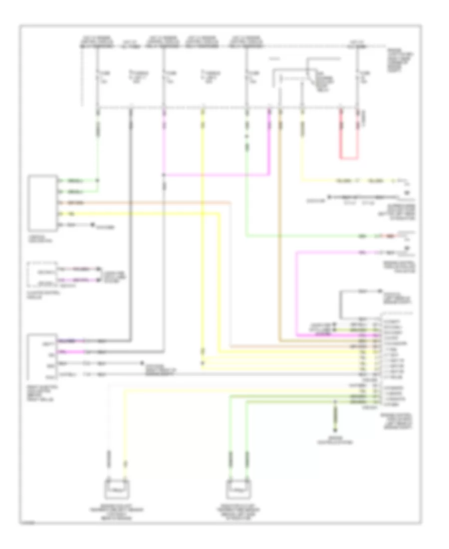
COOLING FAN
Cooling Fan Wiring Diagram for Land Rover Range Rover Autobiography 2014
List of elements for Cooling Fan Wiring Diagram for Land Rover Range Rover Autobiography 2014:
- Air charge coolant pump relay
- B d canh1
- B d canl1
- C11-u1
- C11-u2
- C1bb01b
- C1e120a
- C1e120b
- C2h101a
- Climate control module
- Computer data lines system
- Engine control module (ecm) (left rear of engine compt)
- Engine control module cooling fan motor
- Engine controls system
- Engine coolant temperature (ect) sensor (top right rear of engine)
- Engine junction box (right rear corner of engine compt)
- Front electric cooling fan (behind front grille)
- Fuse 10a
- Fuse 15a
- Fusible link 11 40a
- Fusible link 5 40a
- G g bat1
- G r engts
- G r sen
- G1d121al (left rear of engine compt)
- G1d123bs
- G1d131ar
- G1d133as (right front of engine compt)
- Gnd
- Hot at all times
- Hot w/ engine control module relay energized
- I a engts
- I a radwts
- I t fss
- Ign
- Ms can h
- Ms can l
- O s cacwpr
- O s pcf
- O t eclg2
- O t evf
- Pwm
- Radiator outlet temperature sensor (behind left side of radiator)
- Red
- Supercharge coolant pump (bottom left rear of radiator)
- V v bat 1r
- V v bat 2r
- V v bat 3r
- Vbatt
- Viscous cooling fan
 English