COOLING FAN
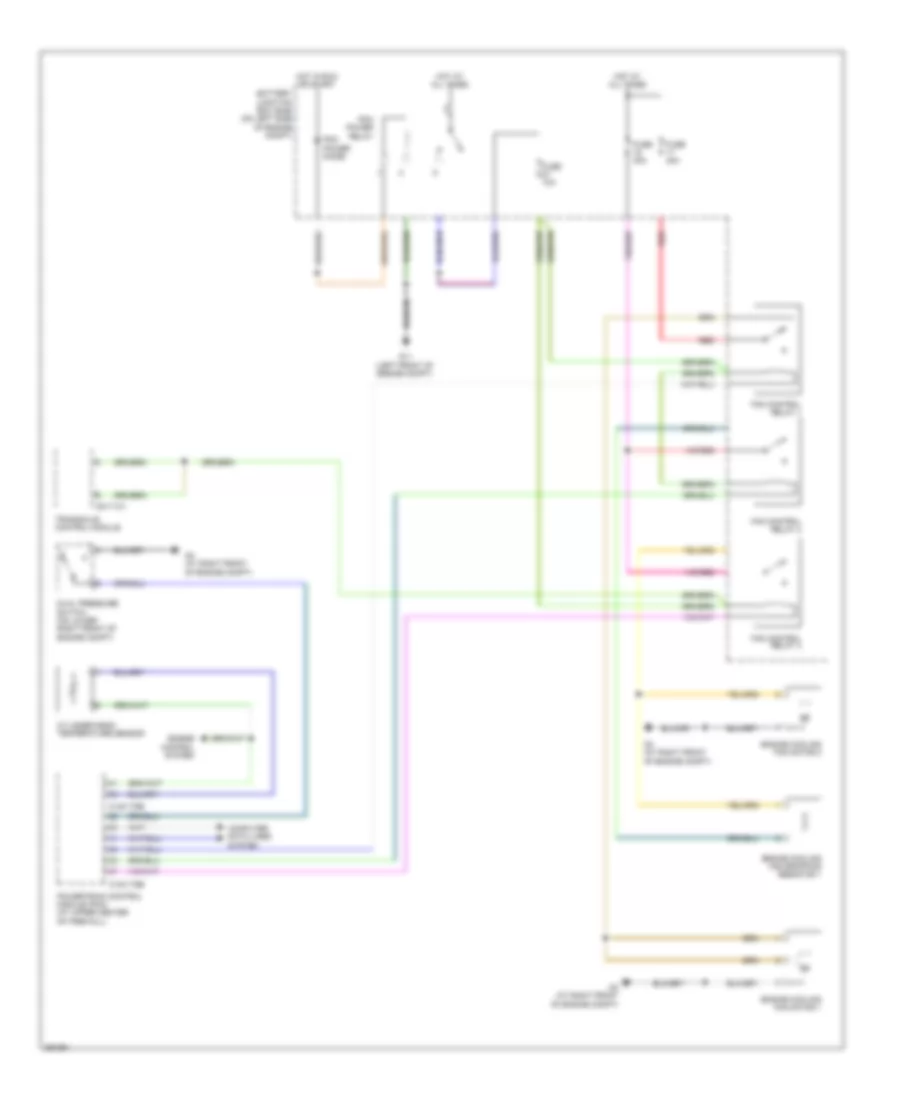
Cooling Fan Wiring Diagram, Except Hybrid for Mazda Tribute i Sport 2008

List of elements for Cooling Fan Wiring Diagram, Except Hybrid for Mazda Tribute i Sport 2008:
- (2.3l)
- (3.0l)
- 0140-175b
- 0140-175e
- 0140-275b
- 0140-275e
- 2.3l
- 3.0l
- Battery junction box (bjb) (on left side of engine compt)
- Computer data lines system
- Cooling fan relay
- Cooling fan resistor (2.3l)
- Cylinder head temperature sensor (2.3l) (on right front of cylinder head)
- Dual pressure switch (on lower right front of engine compt)
- Engine control system
- Engine coolant temperature (ect) sensor (3.0l) (at rear of engine)
- Engine cooling fan motor 1
- Engine cooling fan motor 2
- Fuse 40a
- G11 (left front of engine compt)
- G3 (at right front of engine compt)
- G4 (at right front of engine compt)
- High speed fan control relay
- Hot at all times
- Hot in run or start
- Low speed fan control relay
- Pcm power diode
- Pcm power relay
- Powertrain control module (pcm) (at upper center of firewall)
- Red
Cooling Fan Wiring Diagram, Hybrid for Mazda Tribute i Sport 2008
List of elements for Cooling Fan Wiring Diagram, Hybrid for Mazda Tribute i Sport 2008:
- 0140-175b
- 0140-175e
- 0517-101
- Battery junction box (bjb) (on left side of engine compt)
- Computer data lines system
- Cylinder-head temperature sensor
- Dual pressure switch (on lower right front of engine compt)
- Engine control system
- Engine cooling fan dropping resistor 1
- Engine cooling fan motor 1
- Engine cooling fan motor 2
- Fan control relay 1
- Fan control relay 2
- Fan control relay 3
- Fuse 10a
- Fuse 40a
- G11 (left front of engine compt)
- G3 (at right front of engine compt)
- G4 (at right front of engine compt)
- Hot at all times
- Hot in run or start
- Pcm power diode
- Pcm power relay
- Powertrain control module (pcm) (at upper center of firewall)
- Red
- Transaxle control module