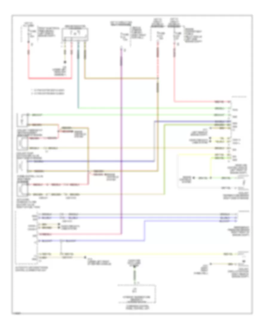
COOLING FAN
Cooling Fan Wiring Diagram for Mercedes-Benz CLA250 4Matic 2014
List of elements for Cooling Fan Wiring Diagram for Mercedes-Benz CLA250 4Matic 2014:
- (+)
- (behind radiator) fan motor
- 30g
- Activated charcoal filter shutoff valve (right of fuel tank)
- Automatic air conditioning control & operating unit
- Can-b h
- Can-b l
- Can-i h
- Can-i l
- Computer data lines system
- Coolant circulation pump (right rear of engine compt)
- Coolant pump switchover valve (right side of engine)
- Coolant temperature sensor (right side of engine)
- Coolant thermostat heating element (right side of engine)
- Engine compartment fuse & relay module (left side engine compt)
- Engine controls system
- Front electrical prefuse box (left side of engine compt)
- Fuse 15a
- Fuse 5a
- Fuse 7.5a
- Fuse 80a
- Gnd
- Hot at all times
- Hot w/ circuit 30g relay energized
- Hot w/ circuit 87m relay energized
- Interior temperature sensor w/ integrated fan
- Lin b13
- Me-sfi (me) control module (left front of engine compt)
- Overhead control panel control unit
- Purge control valve (right rear of engine)
- Pwm
- Red
- Refrigerant pressure sensor (right front of engine compt)
- Sig
- Vehicle interior fuse box (right front footwell)
- W/ fan motor 300w & 400w
- W/ fan motor 600w & 850w
- W11 (left rear of engine compt)
- W12 (under left front of center console)
- W3/1 (right front wheelwell)
- W9 (under left headlight assembly)
- X25/13-c2
- X25/14-c1
- X36/2-c1
 English